EP0068068B1 - Presse plane à découper - Google Patents
Presse plane à découper Download PDFInfo
- Publication number
- EP0068068B1 EP0068068B1 EP82100882A EP82100882A EP0068068B1 EP 0068068 B1 EP0068068 B1 EP 0068068B1 EP 82100882 A EP82100882 A EP 82100882A EP 82100882 A EP82100882 A EP 82100882A EP 0068068 B1 EP0068068 B1 EP 0068068B1
- Authority
- EP
- European Patent Office
- Prior art keywords
- punch
- counter
- die
- extensions
- contact
- Prior art date
- Legal status (The legal status is an assumption and is not a legal conclusion. Google has not performed a legal analysis and makes no representation as to the accuracy of the status listed.)
- Expired
Links
- 238000005520 cutting process Methods 0.000 title claims abstract description 33
- 230000003534 oscillatory effect Effects 0.000 claims abstract description 13
- 239000000463 material Substances 0.000 claims abstract description 9
- 239000002648 laminated material Substances 0.000 claims description 8
- 239000011796 hollow space material Substances 0.000 abstract 1
- 230000010355 oscillation Effects 0.000 description 2
- 208000004188 Tooth Wear Diseases 0.000 description 1
- 230000037431 insertion Effects 0.000 description 1
- 238000003780 insertion Methods 0.000 description 1
- 230000003993 interaction Effects 0.000 description 1
- 230000000452 restraining effect Effects 0.000 description 1
- 238000005096 rolling process Methods 0.000 description 1
Images



Classifications
-
- B—PERFORMING OPERATIONS; TRANSPORTING
- B26—HAND CUTTING TOOLS; CUTTING; SEVERING
- B26F—PERFORATING; PUNCHING; CUTTING-OUT; STAMPING-OUT; SEVERING BY MEANS OTHER THAN CUTTING
- B26F1/00—Perforating; Punching; Cutting-out; Stamping-out; Apparatus therefor
- B26F1/38—Cutting-out; Stamping-out
- B26F1/40—Cutting-out; Stamping-out using a press, e.g. of the ram type
-
- B—PERFORMING OPERATIONS; TRANSPORTING
- B26—HAND CUTTING TOOLS; CUTTING; SEVERING
- B26D—CUTTING; DETAILS COMMON TO MACHINES FOR PERFORATING, PUNCHING, CUTTING-OUT, STAMPING-OUT OR SEVERING
- B26D1/00—Cutting through work characterised by the nature or movement of the cutting member or particular materials not otherwise provided for; Apparatus or machines therefor; Cutting members therefor
- B26D1/01—Cutting through work characterised by the nature or movement of the cutting member or particular materials not otherwise provided for; Apparatus or machines therefor; Cutting members therefor involving a cutting member which does not travel with the work
- B26D1/12—Cutting through work characterised by the nature or movement of the cutting member or particular materials not otherwise provided for; Apparatus or machines therefor; Cutting members therefor involving a cutting member which does not travel with the work having a cutting member moving about an axis
- B26D1/25—Cutting through work characterised by the nature or movement of the cutting member or particular materials not otherwise provided for; Apparatus or machines therefor; Cutting members therefor involving a cutting member which does not travel with the work having a cutting member moving about an axis with a non-circular cutting member
- B26D1/26—Cutting through work characterised by the nature or movement of the cutting member or particular materials not otherwise provided for; Apparatus or machines therefor; Cutting members therefor involving a cutting member which does not travel with the work having a cutting member moving about an axis with a non-circular cutting member moving about an axis substantially perpendicular to the line of cut
- B26D1/30—Cutting through work characterised by the nature or movement of the cutting member or particular materials not otherwise provided for; Apparatus or machines therefor; Cutting members therefor involving a cutting member which does not travel with the work having a cutting member moving about an axis with a non-circular cutting member moving about an axis substantially perpendicular to the line of cut with limited pivotal movement to effect cut
-
- B—PERFORMING OPERATIONS; TRANSPORTING
- B26—HAND CUTTING TOOLS; CUTTING; SEVERING
- B26F—PERFORATING; PUNCHING; CUTTING-OUT; STAMPING-OUT; SEVERING BY MEANS OTHER THAN CUTTING
- B26F1/00—Perforating; Punching; Cutting-out; Stamping-out; Apparatus therefor
- B26F1/38—Cutting-out; Stamping-out
- B26F1/40—Cutting-out; Stamping-out using a press, e.g. of the ram type
- B26F2001/402—Cutting-out; Stamping-out using a press, e.g. of the ram type curvilinear cutting presses, i.e. the stroke comprising an overlay of a linear and a curved movement
-
- Y—GENERAL TAGGING OF NEW TECHNOLOGICAL DEVELOPMENTS; GENERAL TAGGING OF CROSS-SECTIONAL TECHNOLOGIES SPANNING OVER SEVERAL SECTIONS OF THE IPC; TECHNICAL SUBJECTS COVERED BY FORMER USPC CROSS-REFERENCE ART COLLECTIONS [XRACs] AND DIGESTS
- Y10—TECHNICAL SUBJECTS COVERED BY FORMER USPC
- Y10T—TECHNICAL SUBJECTS COVERED BY FORMER US CLASSIFICATION
- Y10T83/00—Cutting
- Y10T83/869—Means to drive or to guide tool
- Y10T83/8874—Uniplanar compound motion
Definitions
- This invention concerns a plane die-cutting machine, suitable for die-cutting laminate material and comprising a plane punch which may be equipped with protruding die-cutting blades and/or bosses, as well as an arc-shaped counter-punch, which is controlled in such a way as to be pressed against laminate work material inserted between the same and the punch and to be simultaneously rotated around a line of instant-contact which progressively traverses the punch.
- GB-A-790361 discloses a plane die-cutting machine for die-cutting laminate material, of the type comprising a plane punch and an arc-shaped counterpunch, which is controlled by means adapted to press the same against the material to be worked, between the punch and counter-punch, and to simultaneous rotate said counter-punch around a line of instantaneous contact which progressively traverses the punch, wherein said punch and counter punch carry extensions which extend alongside the die-cutting area; wherein said control means perform alternate oscillatory movement of the counter-punch extending for a given length beyond the die-cutting area; and wherein said extensions remain permanently in contact also along said given length beyond the die-cutting area.
- An object of this invention is therefore to provide a plane die-cutting machine, which works according to the basic principles of the above mentioned die-cutting machines, but wherein any impact contact between the reciprocally moving parts of same is avoided, though ensuring a maximum of precision and reliability in the die-cutting operation and moreover allowing the best conditions of insertion and feed of the laminar material under work.
- this invention provides a machine for die-cutting laminate material, of the type comprising a punch having a planar working surface, a movable counter-punch having an arc-shaped working surface, control means for controlling the movements of said counter-punch relative to said punch in such a manner that said counter-punch working surface contacts said punch working surface within a die-cutting area, by rotating along a line of contact progressively moving back and forth across said working surfaces, said punch and said counter-punch having respectively plane extensions and arc-shaped counter-extensions located alongside said working surfaces and carrying meshing racks having a plurality of gear teeth to maintain a continuous meshed engagement between said plane extensions and said counter-extensions during alternate oscillatory movement of said counter-punch over the contact extent of said working surfaces and therebeyond, whereby relative shifting between said plane working surface of said punch and said arc-shaped surface of said counter- punch is prevented over the total extent of said meshing racks, characterized in that said control means comprise a cam and cam follower pivotally secured to
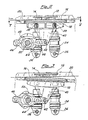
- the plane die-cutting machine comprises, in a frame generally indicated by 10, a punch 12 which may be equipped with protruding blades and/or bosses for die-cutting, as schematically indicated by 14.
- the configuration of the punch operative elements, their structure and the way they are fixed to the punch 12 and, as required, to the counter-punch, are well known to those skilled in the art and therefore will not be herein described nor specifically illustrated.
- Said punch 12, 14 is designed to cooperate with a counter-punch 16, which has a configuration with an essentially arc-shaped outline, for instance consisting of a sector of a cylindrical surface of large radius, said surface being brought into contact with the punch in correspondence to an instantaneous contact line, substantially as described in the above mentioned preceding patent application GB-A-2 049 530. Consequently, the counter- punch 16, which is housed in a supporting frame 18, is caused to roll on the punch 12, 14, carrying out the die-cutting operation of the laminate material 20 placed between said two elements, which each time is fed for a length equal to the die-cutting area. In order to prevent the punch and the counter-punch from reciprocally colliding, extensions are provided integral to both the punch and counter-punch respectively.
- the punch has on its sides two extensions 22, 24 which extend perpendicularly to the contact line between said two operative elements, essentially on the area where the material to be worked 20 is introduced.
- the counter-punch has two extensions 26 and 28 which extend in correspondence to the extensions 22 and 24, obviously with an arc-shaped configuration corresponding to that of the counter-punch itself.
- the extensions 22, 26, as well as the extensions 24, 28 are designed to engage by suitable restraining means which, however, allow the described relative rolling, in the form of reciprocally meshing racks 30 and 32.
- the counter-punch tends to assume the shape of a blotter operating on the plane and fixed punch, with respect to which it carries out an alternate oscillatory movement which is performed by always keeping a reciprocal contact in correspondence to the extensions 22, 26 and 24, 28, as well as in the central area, in correspondence to the punch 12, 14 and counter- punch 16.
- the control means bring the counter-punch near to the ends of its run, that is near to the inversion points in its oscillatory movement, the operative elements 14 and 16 are spaced for a length sufficient to allow the laminate material underworkto be fed between them; the laminate material has a width less than the distance between the parallel extensions 22, 24 and 26, 28.
- the die-cutting machine functions by performing an operative run at each semi-oscillation, with feed of the material to be worked taking place at the end of each semi-oscillation.
- Said feed can be carried out by conventional means, either manually or automatically, in the positions as shown in Figures 1 and 4.
- the operative movement of the counter-punch 16 may be obtained by two series of elements, acting on the supporting frame 18 and adapted to exert a pressure on the punch 12,14 and to perform said alternate oscillatory movement.
- the pressure of the counter-punch on the punch can be exerted by means of a series of cylinders, for instance four pneumatic cylinders 34 pivoted on one side at 36 to the machine frame 10 acting on the counter- punch through ball joints 38.
- the support 18 of the counter-punch 16 shows an appendix 40, which is connected by a pivot 42 to a rod 44 capable of alternately oscillating about said pivot 42 in two directions, between the positions of Figures 3 and 4, passing through the position of Figure 2.
- the rod 44 is guided by rollers 46, on which an eccentric cam 48 operates, said cam being mounted on an eccentric control shaft 50 which is rotated by means of suitable motor means.
- This oscillation control means and the cylinders 34 allows the desired movement of counter- punch 16 to be obtained in an extremely secure and reliable way, without excessive mechanical stress.
Landscapes
- Life Sciences & Earth Sciences (AREA)
- Forests & Forestry (AREA)
- Engineering & Computer Science (AREA)
- Mechanical Engineering (AREA)
- Perforating, Stamping-Out Or Severing By Means Other Than Cutting (AREA)
- Punching Or Piercing (AREA)
- Shovels (AREA)
- Crushing And Grinding (AREA)
Claims (4)
Priority Applications (1)
| Application Number | Priority Date | Filing Date | Title |
|---|---|---|---|
| AT82100882T ATE34326T1 (de) | 1981-02-25 | 1982-02-08 | Stempelschneidmaschine. |
Applications Claiming Priority (2)
| Application Number | Priority Date | Filing Date | Title |
|---|---|---|---|
| IT1996181 | 1981-02-25 | ||
| IT19961/81A IT1135615B (it) | 1981-02-25 | 1981-02-25 | Fustellatrice piana |
Publications (3)
| Publication Number | Publication Date |
|---|---|
| EP0068068A2 EP0068068A2 (fr) | 1983-01-05 |
| EP0068068A3 EP0068068A3 (en) | 1984-03-07 |
| EP0068068B1 true EP0068068B1 (fr) | 1988-05-18 |
Family
ID=11162666
Family Applications (1)
| Application Number | Title | Priority Date | Filing Date |
|---|---|---|---|
| EP82100882A Expired EP0068068B1 (fr) | 1981-02-25 | 1982-02-08 | Presse plane à découper |
Country Status (8)
| Country | Link |
|---|---|
| US (1) | US4516457A (fr) |
| EP (1) | EP0068068B1 (fr) |
| AT (1) | ATE34326T1 (fr) |
| BR (1) | BR8201058A (fr) |
| CA (1) | CA1178884A (fr) |
| DE (1) | DE3278493D1 (fr) |
| ES (1) | ES8302493A1 (fr) |
| IT (1) | IT1135615B (fr) |
Families Citing this family (4)
| Publication number | Priority date | Publication date | Assignee | Title |
|---|---|---|---|---|
| US5261262A (en) * | 1992-03-02 | 1993-11-16 | Wallis Bernard J | Method and apparatus for cutting corrugated webs having louvers |
| EP3656518B1 (fr) * | 2018-11-20 | 2021-01-20 | Industrias Tecnológicas de Mecanización y Automatizaciòn, S.A. | Dispositif de découpage à l'emporte-pièce et d'éjection de bouchons en elastomère |
| DE102019211335A1 (de) * | 2019-07-30 | 2021-02-04 | Multivac Sepp Haggenmüller Se & Co. Kg | Verpackungsmaschine mit schneidstation |
| CN114670287B (zh) * | 2022-04-20 | 2022-11-25 | 北京黎马敦太平洋包装有限公司 | 模切设备 |
Family Cites Families (13)
| Publication number | Priority date | Publication date | Assignee | Title |
|---|---|---|---|---|
| US2130818A (en) * | 1936-11-25 | 1938-09-20 | Andrew W Soderberg | Method of shearing |
| GB721875A (en) * | 1951-05-25 | 1955-01-12 | Tom Rowlands | Improvements in or relating to machines for performing cutting, creasing, printing and like operations on paper, cardboard and like materials |
| US2737238A (en) * | 1951-05-25 | 1956-03-06 | Thrissell Engineering Company | Apparatus for cutting and creasing sheet material |
| DE1020521B (de) * | 1952-07-29 | 1957-12-05 | S a S Corrugated Paper Machinery Co., Inc., Brooklyn, N. Y. (V. St. A.) | Vorrichtung zum Prägen und Stanzen von Bogen aus Papier, Pappe od. dgl |
| GB790361A (en) * | 1954-05-04 | 1958-02-05 | Tom Rowlands | Improvements in or relating to machines for performing cutting, creasing, and like operations on paper, cardboard, and like materials |
| DE1088332B (de) * | 1958-02-20 | 1960-09-01 | Etudes De Machines Speciales | Flachschneidpresse, insbesondere fuer Zuschnitte aus Pappe |
| FR1192566A (fr) * | 1958-02-20 | 1959-10-27 | Etudes De Machines Speciales | Perfectionnement aux presses à découper à plat par filets ou similaires |
| CH381092A (fr) * | 1962-10-23 | 1964-08-14 | Bobst Fils Sa J | Presse comportant une platine mobile mue par des genouilléres |
| GB1201048A (en) * | 1967-11-10 | 1970-08-05 | Moeller & Neumann Gmbh | Shearing line for heavy plates |
| GB1439464A (en) * | 1972-09-09 | 1976-06-16 | Handley A R | Shear cutter |
| AU2961277A (en) * | 1976-10-18 | 1979-04-26 | Davy Loewy Ltd | Rolling cut shear |
| IT1113980B (it) * | 1979-05-14 | 1986-01-27 | Bartesaghi Angelo | Apparecchiatura fustellatrice piana |
| DE3015913A1 (de) * | 1980-04-25 | 1981-10-29 | Thyssen Industrie Ag, 4300 Essen | Servo-hydraulische schneidpresse bzw. schere zum schneiden von insbesondere duennen blechen |
-
1981
- 1981-02-25 IT IT19961/81A patent/IT1135615B/it active
-
1982
- 1982-02-08 AT AT82100882T patent/ATE34326T1/de not_active IP Right Cessation
- 1982-02-08 DE DE8282100882T patent/DE3278493D1/de not_active Expired
- 1982-02-08 EP EP82100882A patent/EP0068068B1/fr not_active Expired
- 1982-02-15 CA CA000396261A patent/CA1178884A/fr not_active Expired
- 1982-02-18 ES ES509724A patent/ES8302493A1/es not_active Expired
- 1982-02-25 BR BR8201058A patent/BR8201058A/pt not_active IP Right Cessation
-
1984
- 1984-04-18 US US06/601,116 patent/US4516457A/en not_active Expired - Lifetime
Also Published As
| Publication number | Publication date |
|---|---|
| DE3278493D1 (en) | 1988-06-23 |
| IT1135615B (it) | 1986-08-27 |
| BR8201058A (pt) | 1983-01-11 |
| EP0068068A2 (fr) | 1983-01-05 |
| ES509724A0 (es) | 1983-01-16 |
| IT8119961A0 (it) | 1981-02-25 |
| ES8302493A1 (es) | 1983-01-16 |
| EP0068068A3 (en) | 1984-03-07 |
| CA1178884A (fr) | 1984-12-04 |
| ATE34326T1 (de) | 1988-06-15 |
| US4516457A (en) | 1985-05-14 |
Similar Documents
| Publication | Publication Date | Title |
|---|---|---|
| US4241479A (en) | Needle felt machine with a guiding apparatus for the needle beam | |
| US4245538A (en) | Process and apparatus for cutting portions out of a web of material | |
| US4922775A (en) | Device for cutting contoured labels | |
| US3897705A (en) | Device for slitting sheet material | |
| US3057241A (en) | Flat-rib type cutting press | |
| US4328729A (en) | Plane die-cutting machine | |
| US4516457A (en) | Plane die-cutting machine | |
| US4437373A (en) | Arrangement for perforating or cutting foils | |
| GB1575725A (en) | Machine tool carriage arrangement | |
| US5097577A (en) | Machine with intermittently rotary workpiece-holding table for working and assembly of high-precision pieces | |
| US2857968A (en) | Perforating machine | |
| EP0366108B1 (fr) | Dispositif pour avancer pas à pas une bande | |
| US5110026A (en) | Apparatus for a stepwise advancing of a web-shaped workpiece | |
| EP1074324B1 (fr) | Dispositif pour couper des feuilles métalliques | |
| JPH0626732B2 (ja) | 曲げ機械の曲げブレード取付構造 | |
| US3570340A (en) | Roller diecutting machine or the like | |
| US4852440A (en) | Flying shear or stamping apparatus for strip material | |
| EP0281202A1 (fr) | Dispositif pour perforer une bande en travers | |
| EP0421497A1 (fr) | Procédure et disposition pour la réalisation intermittente d'un traitement subséquent d'un ruban | |
| SU1117227A1 (ru) | Устройство дл штамповки деталей из ленты | |
| US3030883A (en) | Engraver's automatic rotary press | |
| US3159070A (en) | Thread cutting device | |
| SU1418007A1 (ru) | Устройство дл обработки листового материала | |
| SU902997A1 (ru) | Ручные ножницы | |
| SU473573A1 (ru) | Устройство дл резки изделий |
Legal Events
| Date | Code | Title | Description |
|---|---|---|---|
| PUAI | Public reference made under article 153(3) epc to a published international application that has entered the european phase |
Free format text: ORIGINAL CODE: 0009012 |
|
| AK | Designated contracting states |
Designated state(s): AT BE CH DE FR GB LI NL SE |
|
| PUAL | Search report despatched |
Free format text: ORIGINAL CODE: 0009013 |
|
| AK | Designated contracting states |
Designated state(s): AT BE CH DE FR GB LI NL SE |
|
| 17P | Request for examination filed |
Effective date: 19840830 |
|
| GRAA | (expected) grant |
Free format text: ORIGINAL CODE: 0009210 |
|
| AK | Designated contracting states |
Kind code of ref document: B1 Designated state(s): AT BE CH DE FR GB LI NL SE |
|
| PG25 | Lapsed in a contracting state [announced via postgrant information from national office to epo] |
Ref country code: NL Effective date: 19880518 Ref country code: AT Effective date: 19880518 |
|
| REF | Corresponds to: |
Ref document number: 34326 Country of ref document: AT Date of ref document: 19880615 Kind code of ref document: T |
|
| PG25 | Lapsed in a contracting state [announced via postgrant information from national office to epo] |
Ref country code: SE Effective date: 19880531 |
|
| REF | Corresponds to: |
Ref document number: 3278493 Country of ref document: DE Date of ref document: 19880623 |
|
| ET | Fr: translation filed | ||
| NLV1 | Nl: lapsed or annulled due to failure to fulfill the requirements of art. 29p and 29m of the patents act | ||
| PLBE | No opposition filed within time limit |
Free format text: ORIGINAL CODE: 0009261 |
|
| STAA | Information on the status of an ep patent application or granted ep patent |
Free format text: STATUS: NO OPPOSITION FILED WITHIN TIME LIMIT |
|
| 26N | No opposition filed | ||
| PGFP | Annual fee paid to national office [announced via postgrant information from national office to epo] |
Ref country code: BE Payment date: 19900131 Year of fee payment: 9 |
|
| PG25 | Lapsed in a contracting state [announced via postgrant information from national office to epo] |
Ref country code: BE Effective date: 19910228 |
|
| PGFP | Annual fee paid to national office [announced via postgrant information from national office to epo] |
Ref country code: FR Payment date: 20010109 Year of fee payment: 20 |
|
| PGFP | Annual fee paid to national office [announced via postgrant information from national office to epo] |
Ref country code: GB Payment date: 20010207 Year of fee payment: 20 |
|
| PGFP | Annual fee paid to national office [announced via postgrant information from national office to epo] |
Ref country code: CH Payment date: 20010214 Year of fee payment: 20 |
|
| PGFP | Annual fee paid to national office [announced via postgrant information from national office to epo] |
Ref country code: DE Payment date: 20010425 Year of fee payment: 20 |
|
| REG | Reference to a national code |
Ref country code: GB Ref legal event code: IF02 |
|
| PG25 | Lapsed in a contracting state [announced via postgrant information from national office to epo] |
Ref country code: LI Free format text: LAPSE BECAUSE OF EXPIRATION OF PROTECTION Effective date: 20020207 Ref country code: GB Free format text: LAPSE BECAUSE OF EXPIRATION OF PROTECTION Effective date: 20020207 Ref country code: CH Free format text: LAPSE BECAUSE OF EXPIRATION OF PROTECTION Effective date: 20020207 |
|
| REG | Reference to a national code |
Ref country code: GB Ref legal event code: PE20 Effective date: 20020207 |
|
| REG | Reference to a national code |
Ref country code: CH Ref legal event code: PL |