EP0068082B1 - Procédé pour la mesure des déviations de la rondeur de corps rotation-symétriques - Google Patents
Procédé pour la mesure des déviations de la rondeur de corps rotation-symétriques Download PDFInfo
- Publication number
- EP0068082B1 EP0068082B1 EP82102711A EP82102711A EP0068082B1 EP 0068082 B1 EP0068082 B1 EP 0068082B1 EP 82102711 A EP82102711 A EP 82102711A EP 82102711 A EP82102711 A EP 82102711A EP 0068082 B1 EP0068082 B1 EP 0068082B1
- Authority
- EP
- European Patent Office
- Prior art keywords
- rotation
- roundness
- digital computer
- rotational solid
- axis
- Prior art date
- Legal status (The legal status is an assumption and is not a legal conclusion. Google has not performed a legal analysis and makes no representation as to the accuracy of the status listed.)
- Expired
Links
- 238000000034 method Methods 0.000 title claims abstract description 25
- 239000000523 sample Substances 0.000 claims abstract description 8
- 239000007787 solid Substances 0.000 claims abstract 19
- 238000005259 measurement Methods 0.000 claims description 10
- 238000012937 correction Methods 0.000 claims description 4
- 230000000063 preceeding effect Effects 0.000 claims 2
- 238000010586 diagram Methods 0.000 description 9
- 230000006870 function Effects 0.000 description 7
- 238000011161 development Methods 0.000 description 3
- 230000015572 biosynthetic process Effects 0.000 description 1
- 230000008878 coupling Effects 0.000 description 1
- 238000010168 coupling process Methods 0.000 description 1
- 238000005859 coupling reaction Methods 0.000 description 1
- 230000001419 dependent effect Effects 0.000 description 1
- 230000008030 elimination Effects 0.000 description 1
- 238000003379 elimination reaction Methods 0.000 description 1
- 238000011156 evaluation Methods 0.000 description 1
- 238000000926 separation method Methods 0.000 description 1
Images
Classifications
-
- G—PHYSICS
- G01—MEASURING; TESTING
- G01B—MEASURING LENGTH, THICKNESS OR SIMILAR LINEAR DIMENSIONS; MEASURING ANGLES; MEASURING AREAS; MEASURING IRREGULARITIES OF SURFACES OR CONTOURS
- G01B7/00—Measuring arrangements characterised by the use of electric or magnetic techniques
- G01B7/28—Measuring arrangements characterised by the use of electric or magnetic techniques for measuring contours or curvatures
- G01B7/282—Measuring arrangements characterised by the use of electric or magnetic techniques for measuring contours or curvatures for measuring roundness
-
- G—PHYSICS
- G01—MEASURING; TESTING
- G01B—MEASURING LENGTH, THICKNESS OR SIMILAR LINEAR DIMENSIONS; MEASURING ANGLES; MEASURING AREAS; MEASURING IRREGULARITIES OF SURFACES OR CONTOURS
- G01B21/00—Measuring arrangements or details thereof, where the measuring technique is not covered by the other groups of this subclass, unspecified or not relevant
- G01B21/20—Measuring arrangements or details thereof, where the measuring technique is not covered by the other groups of this subclass, unspecified or not relevant for measuring contours or curvatures, e.g. determining profile
-
- G—PHYSICS
- G01—MEASURING; TESTING
- G01B—MEASURING LENGTH, THICKNESS OR SIMILAR LINEAR DIMENSIONS; MEASURING ANGLES; MEASURING AREAS; MEASURING IRREGULARITIES OF SURFACES OR CONTOURS
- G01B7/00—Measuring arrangements characterised by the use of electric or magnetic techniques
- G01B7/34—Measuring arrangements characterised by the use of electric or magnetic techniques for measuring roughness or irregularity of surfaces
- G01B7/345—Measuring arrangements characterised by the use of electric or magnetic techniques for measuring roughness or irregularity of surfaces for measuring evenness
Definitions
- the invention is based on a method for determining the roundness deviations of a rotating body according to the preamble of claim 1 in accordance with DE-A-24 25 226.
- DE-A-24 59 678 describes a device for measuring the roundness of a workpiece, in which the analog output signal of a detector for sensing the workpiece size, which consists of the sum of a signal caused by eccentricity and a signal caused by rounding errors, is provided once via a device for Absolute value determination and, on the other hand, a low-pass filter and a further device for determining the absolute value are fed to a computing device, at whose output the absolute value of the rounding error appears, which can be displayed in a display device in analog or digital form.
- US-A-3 231 979 describes a method for checking the surface shape of a rotating body by means of an analog length measuring probe. that generates an overall electrical measurement that corresponds to the surface profile and the centering error; in addition, an electrical sinusoidal correction quantity is generated that corresponds to the centering error.
- the total measurement quantity and the correction quantity are fed to a difference-forming measuring instrument for the difference formation.
- DE-A-24 25 226 specifies a method for measuring the surface of a workpiece, in which a sensor is guided across the surface in a traverse in order to supply analog signals which are characteristic of the profile of the surface and which are provided by an analog-digital converter implemented and a Dig i are supplied talrechner. From these digital values and from digital signals, which represent the relative angular position between the sensor and the workpiece, parameters for a reference line are determined, which is centered in the middle of the scanned workpiece and can be related to the roundness deviations of the surface of the workpiece. The calculation of the reference line is based on an equation for an eccentric circle that contains only the first-order eccentricity element.
- the invention has the object of providing a method for determining the round i he tsabweichitch a rotary body of the above-mentioned type indicate which allows with simple means, a highly accurate determination of the roundness deviations of the rotating body even without exact centering with respect to the axis of rotation.
- the advantages achieved by the invention consist in particular in that the rotary body can be arranged relatively strongly eccentrically to the axis of rotation, so that a time-consuming and costly accurate centering is unnecessary. All important data such as the size and angle of the roundness deviations and the eccentricity, elliptical errors, triangular errors as well as further Fourier coefficients of the roundness deviations and the concentricity of several rotating surfaces of a rotating body can be determined by the computer. Furthermore, after a single calibration process with a teaching cylinder, the absolute dimension of the radius of the rotating body can be specified.
- a digital electrical scanning device incrementmental or absolute measuring probe
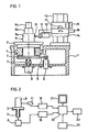
- FIG. 1 a device for measuring the roundness deviations of rotating bodies is shown schematically.
- a rotary table 2 with a spindle 3 is rotatably mounted in a precision bearing 4 in a stationary frame 1.
- the spindle 3 is driven by a belt 5 by a motor 6 fastened in the frame 1.
- the spindle 3 is rigidly connected to an angle measuring device 8 via a coupling 7.
- a rotating body 9 with three rotating surfaces 9a, 9b, 9c is arranged on the surface of the rotary table 2.
- the rotating surfaces 9a. 9b, 9c of the rotating rotary body 9 are scanned according to the invention by the scanning head 10 of a digital scanning device 11 which is carried by an arm 12.
- a vertical column 13 is fastened with a vertical slide 14, which can be adjusted in height by means of an adjusting screw 15.
- a horizontal slide 16 is arranged, which is connected to the arm 12 and can be adjusted horizontally by means of an adjusting screw 17.
- FIG 2 the measuring device according to Figure 1 with the rotary table 2, the spindle 3, the angle measuring device 8, the rotating body 9 and the scanning device 11 is shown in simplified form.
- the digital output signals of the scanning device 11 are fed via an up / down counter 18 and the digital output signals of the angle measuring device 8 via an up / down counter 19 to a digital computer 20 which is connected to a display unit 21 and a printing device 22 and acted upon by an alphanumeric input unit 23 is.
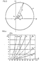
- FIG. 3 shows a circular rotary body K with the radius R, the center A of which is shifted by an eccentricity e with respect to an axis of rotation 0.
- the axis of rotation 0 may be in the origin of a coordinate system y, x, so that the center A of the rotating body K has the coordinates x o , y o .
- the eccentricity e includes the angle ⁇ with the x-axis and the instantaneous beam r includes the angle ⁇ with the x-axis.
- Figure 3 shows the instantaneous beam r as a function of the angle ⁇ from the equation the relationship and after development into a Fourier series
- F 2 F 20 . cos 2 ( ⁇ - a) with the period ⁇ shows an actually circular rotation body K with an eccentric clamping an apparent elliptical error.
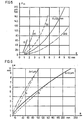
- the size of the maximum elliptical error F 20 is shown as a diagram in FIGS. 4 and 5 as a function of the eccentricity e and the radius R of the rotating body K.
- the dashed lines a and b in FIG. 6 show that the permissible eccentricity e can be roughly applied with R / 10 or R / 20 if ⁇ should remain less than 1 ⁇ m or less than 0.1 ⁇ m. Since the term F 3 and the following terms of the polynomial can be neglected, the instantaneous ray r is a function of the angle ⁇
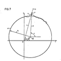
- the individual measured values M i are regularly distributed over the angle 2 ⁇ .
- 8 n measuring positions are defined by the angle measuring device over the angle 2 ⁇ .
- the number n must be chosen so large that the profile of the rotating surface 9a, 9b, 9c of the rotating body 9 to be tested can be determined with sufficient certainty.
- the number n is limited upwards by the storage capacity of the digital computer 20.
- the number n of measurement positions will be between 200 and 10,000. 200 measured values are to be regarded as a minimum for determining the roundness deviations of the rotating body (9).
- a correction value E is calculated from this the one for calculating the absolute radius R of the rotating body 9 is used.
- the digital computer 20 is used to store the measured values, to eliminate the eccentricity e and the apparent elliptical error F 2 and, if appropriate, the higher-order errors to calculate the roundness deviations and for Fourier analysis of the roundness deviations and, if appropriate, to statistically evaluate a series of roundness measurements; Furthermore, the concentricity of a plurality of rotation surfaces 9a, 9b, 9c of the rotation body 9 or the oblique position of the axis of rotation of the rotation body 9 with respect to the contact surface can be determined.
- the measurement result can be displayed on the printing device 22 in the form of an X-Y recorder or a polar chart recorder or on a display device 21 with a screen in the form of a polar roundness error diagram.
Landscapes
- Physics & Mathematics (AREA)
- General Physics & Mathematics (AREA)
- Length Measuring Devices With Unspecified Measuring Means (AREA)
- A Measuring Device Byusing Mechanical Method (AREA)
- Length Measuring Devices By Optical Means (AREA)
- Measurement Of Length, Angles, Or The Like Using Electric Or Magnetic Means (AREA)
Claims (5)
Priority Applications (1)
| Application Number | Priority Date | Filing Date | Title |
|---|---|---|---|
| AT82102711T ATE16636T1 (de) | 1981-06-13 | 1982-03-31 | Verfahren zur messung der rundheitsabweichungen von rotations-koerpern. |
Applications Claiming Priority (2)
| Application Number | Priority Date | Filing Date | Title |
|---|---|---|---|
| DE3123489 | 1981-06-13 | ||
| DE19813123489 DE3123489A1 (de) | 1981-06-13 | 1981-06-13 | Verfahren zur messung der rundheitsabweichungen von rotationskoerpern und einrichtungen zur durchfuehrung des verfahrens |
Publications (3)
| Publication Number | Publication Date |
|---|---|
| EP0068082A2 EP0068082A2 (fr) | 1983-01-05 |
| EP0068082A3 EP0068082A3 (en) | 1983-02-09 |
| EP0068082B1 true EP0068082B1 (fr) | 1985-11-21 |
Family
ID=6134632
Family Applications (1)
| Application Number | Title | Priority Date | Filing Date |
|---|---|---|---|
| EP82102711A Expired EP0068082B1 (fr) | 1981-06-13 | 1982-03-31 | Procédé pour la mesure des déviations de la rondeur de corps rotation-symétriques |
Country Status (4)
| Country | Link |
|---|---|
| EP (1) | EP0068082B1 (fr) |
| JP (1) | JPS57207813A (fr) |
| AT (1) | ATE16636T1 (fr) |
| DE (1) | DE3123489A1 (fr) |
Families Citing this family (28)
| Publication number | Priority date | Publication date | Assignee | Title |
|---|---|---|---|---|
| GB2148007B (en) * | 1983-10-01 | 1988-02-10 | Rolls Royce Motor Cars | Profile checking apparatus |
| US4642902A (en) * | 1984-06-26 | 1987-02-17 | Siemens Aktiengesellschaft | Apparatus for determining the deviations from a circular form in a dynamically balanced part |
| DE3540649C2 (de) * | 1984-11-15 | 1993-01-14 | ELGEMA GmbH, 8057 Eching | Vorrichtung zum Messen der Profilform von zylindrischen Werkstückflächen |
| GB8605324D0 (en) * | 1986-03-04 | 1986-04-09 | Rank Taylor Hobson Ltd | Metrological apparatus |
| US4800652A (en) * | 1987-09-25 | 1989-01-31 | The Timken Company | Machine for measuring generally circular objects in cylindrical coordinates |
| DE3807551A1 (de) * | 1988-03-08 | 1989-09-21 | Teves Gmbh Alfred | Aufnahmevorrichtung fuer eine bremstrommel |
| DE3832331A1 (de) * | 1988-09-23 | 1990-03-29 | Mauser Werke Oberndorf | Messmaschine |
| JPH02105007A (ja) * | 1988-10-14 | 1990-04-17 | Topy Ind Ltd | ホイールリム等の形状測定方法およびその装置 |
| US5151870A (en) * | 1989-11-17 | 1992-09-29 | Illinois Tool Works Inc. | Apparatus and method for determining a center and measuring with reference thereto |
| AT399396B (de) * | 1990-03-29 | 1995-04-25 | Oesterr Forsch Seibersdorf | Verfahren zur bestimmung des achsenverlaufes eines langgestreckten gegenstandes |
| GB2294327A (en) * | 1994-10-18 | 1996-04-24 | Rank Taylor Hobson Ltd | Roundness measuring |
| GB2317453B (en) * | 1996-09-20 | 2000-12-06 | Rank Taylor Hobson Ltd | Bearing measurement system |
| DE19851954A1 (de) * | 1998-11-11 | 2000-05-18 | Mahle Gmbh | Messverfahren und -system für Rotationsteile, insbesondere für Kolben von Kolbenmaschinen |
| JP3738844B2 (ja) * | 2002-09-04 | 2006-01-25 | 株式会社東京精密 | 真円度測定機 |
| JP4663385B2 (ja) * | 2005-04-18 | 2011-04-06 | 株式会社ブリヂストン | 回転体表面の凹凸データ補正方法 |
| DE102006015627B4 (de) * | 2006-03-31 | 2008-03-27 | Innovent E.V. | Verfahren und Vorrichtung zur Bestimmung und Vermessung von Formabweichungen und Welligkeiten an rotationssymmetrischen Teilen |
| JP2008286535A (ja) | 2007-05-15 | 2008-11-27 | Mitsutoyo Corp | 真円度測定装置、真円度測定方法、及び真円度測定プログラム |
| DE102009032353A1 (de) | 2009-07-08 | 2011-09-08 | Hommel-Etamic Gmbh | Verfahren zur Ermittlung der Form eines Werkstücks |
| US9133750B2 (en) | 2009-07-30 | 2015-09-15 | GM Global Technology Operations LLC | Method and system for verifying the operation of an SCR catalyst |
| DE102009042252B4 (de) | 2009-09-22 | 2014-03-06 | Jenoptik Industrial Metrology Germany Gmbh | Meßvorrichtung |
| GB2478303B (en) | 2010-03-02 | 2018-03-07 | Taylor Hobson Ltd | Surface measurement instrument and calibration thereof |
| DE102010013069B4 (de) | 2010-03-26 | 2012-12-06 | Hommel-Etamic Gmbh | Meßvorrichtung |
| DE102010035147B4 (de) | 2010-08-23 | 2016-07-28 | Jenoptik Industrial Metrology Germany Gmbh | Meßvorrichtung |
| CN102147331B (zh) * | 2010-11-25 | 2012-09-05 | 哈尔滨工业大学 | 基于cnc齿轮测量中心的装卡偏心误差补偿方法 |
| DE102012018580B4 (de) | 2012-09-20 | 2015-06-11 | Jenoptik Industrial Metrology Germany Gmbh | Messvorrichtung und Messverfahren zur Inprozess-Messung an Prüflingen während eines Bearbeitungsvorganges an einer Bearbeitungsmaschine, insbesondere einer Schleifmaschine |
| CN110530306B (zh) * | 2019-08-27 | 2020-10-20 | 大连理工大学 | 一种基于实测跳动数据的典型回转体零件表征方法 |
| CN111397469B (zh) * | 2020-04-09 | 2024-12-24 | 山东交通学院 | 一种圆柱间歇凸轮廓面误差和动力学检测系统及方法 |
| CN116067293A (zh) * | 2023-01-05 | 2023-05-05 | 福建工程学院 | 轴承外径非接触测量方法 |
Family Cites Families (5)
| Publication number | Priority date | Publication date | Assignee | Title |
|---|---|---|---|---|
| DE1100978B (de) * | 1958-07-11 | 1961-03-02 | Johannes Perthen Dr Ing | Verfahren und Einrichtung zum Pruefen der Oberflaechen- und Fehlgestalt eines Werkstueckes |
| GB981865A (en) * | 1960-02-17 | 1965-01-27 | Rank Precision Ind Ltd | Measuring and recording arrangements |
| GB933785A (en) * | 1960-11-16 | 1963-08-14 | Rank Precision Ind Ltd | Improvements in or relating to testing the profiles of surface sections |
| DE1302862B (fr) * | 1962-08-28 | 1971-01-07 | ||
| JPS5698602A (en) * | 1980-01-11 | 1981-08-08 | Mitsubishi Electric Corp | Shape measurement method for cylinder or column |
-
1981
- 1981-06-13 DE DE19813123489 patent/DE3123489A1/de not_active Ceased
-
1982
- 1982-03-31 AT AT82102711T patent/ATE16636T1/de not_active IP Right Cessation
- 1982-03-31 EP EP82102711A patent/EP0068082B1/fr not_active Expired
- 1982-05-27 JP JP57088975A patent/JPS57207813A/ja active Pending
Non-Patent Citations (1)
| Title |
|---|
| Feinwerktechnik und Messtechnik 87 (1979) 5, Seiten 227-232 * |
Also Published As
| Publication number | Publication date |
|---|---|
| ATE16636T1 (de) | 1985-12-15 |
| DE3123489A1 (de) | 1982-12-30 |
| EP0068082A3 (en) | 1983-02-09 |
| JPS57207813A (en) | 1982-12-20 |
| EP0068082A2 (fr) | 1983-01-05 |
Similar Documents
| Publication | Publication Date | Title |
|---|---|---|
| EP0068082B1 (fr) | Procédé pour la mesure des déviations de la rondeur de corps rotation-symétriques | |
| DE60315050T2 (de) | Vorrichtung und verfahren zur messung, kompensation und prüfung eines numerisch gesteuerten werkzeugskopfes und/oder tisches | |
| EP2834595B1 (fr) | Méthode et appareil pour la réduction des erreurs associées à un dispositif de rotation lors de la détermination des coordonnées d'une pièce ou lors de l'usinage d'une pièce | |
| DE60018412T2 (de) | Steuergerät für messinstrument | |
| EP3049758B1 (fr) | Réduction d'erreurs d'un dispositif de rotation qui est utilisée lors de la détermination de coordonnées d'une pièce ou lors de l'usinage d'une pièce | |
| EP2729768B1 (fr) | Calibrage et fonctionnement de dispositifs rotatifs, en particulier pour les têtes de détection et/ou les palpeurs des appareils de mesure de coordonnées | |
| DE69532380T2 (de) | Rundheitsmessen | |
| EP2108105B1 (fr) | Procédé de détermination d'une grandeur d'influence sur l'excentricité dans un dispositif de mesure d'angle | |
| DE60311527T2 (de) | Werkstückinspektionsverfahren und vorrichtung | |
| DE69114869T2 (de) | Verfahren zur Bestimmung des Profils von Reifen. | |
| EP0732563A1 (fr) | Machine de mesure de coördonnées avec dispositif pour la détermination de la rugosité | |
| DE10115288B4 (de) | Messvorrichtung für Oberflächenstrukturen und Messverfahren für Oberflächenstrukturen | |
| EP1923670A1 (fr) | Dispositif de mesure de position | |
| DE69204853T2 (de) | Verfahren und vorrichtung zum kontrollieren der merkmale einer nockenwelle. | |
| EP4102173A1 (fr) | Procédé de positionnement d'un corps doté d'une échelle angulaire | |
| DE1302862B (fr) | ||
| WO1986002996A1 (fr) | Dispositif de mesure du profil de surfaces cylindriques de pieces a usiner | |
| EP0106181B1 (fr) | Procédé d'essai pour déterminer l'exactitude de machines à outil et dispositif pour la mise en oeuvre | |
| DD226063A5 (de) | Geraet und verfahren zur pruefung des zahnflankenprofils und der zahnflankenlinien von zahnraedern auf verzahnmaschinen oder zahnflankenschleifmaschinen | |
| DE69318090T2 (de) | Verfahren zum Messen und Prüfen von Schraubengewinden und ähnlichen Nuten | |
| DE2938662C2 (fr) | ||
| DE4134690C2 (de) | Verfahren und Vorrichtung zur Messung der Form, Größe und Raumlage koaxialer Rotationsflächen und dazu senkrechter Stirnflächen an walzenförmigen Werkstücken | |
| EP0514726B1 (fr) | Méthode pour considérer, pendant l'équilibrage, la déviation de position des manetons de la bielle d'un vilebrequin et dispositif pour cela | |
| DE2354248A1 (de) | Verfahren und geraet zur pruefung eines drehkoerpers auf unregelmaessigkeiten seiner abmessungen | |
| DE102017119488B3 (de) | Verfahren zum Bestimmen der Summenteilungsabweichungen von Positionsverkörperungen eines Werkstücks mit einer Kreisteilung |
Legal Events
| Date | Code | Title | Description |
|---|---|---|---|
| PUAI | Public reference made under article 153(3) epc to a published international application that has entered the european phase |
Free format text: ORIGINAL CODE: 0009012 |
|
| PUAL | Search report despatched |
Free format text: ORIGINAL CODE: 0009013 |
|
| 17P | Request for examination filed |
Effective date: 19820407 |
|
| AK | Designated contracting states |
Designated state(s): AT CH FR GB IT LI NL SE |
|
| AK | Designated contracting states |
Designated state(s): AT CH FR GB IT LI NL SE |
|
| ITF | It: translation for a ep patent filed | ||
| GRAA | (expected) grant |
Free format text: ORIGINAL CODE: 0009210 |
|
| AK | Designated contracting states |
Designated state(s): AT CH FR GB IT LI NL SE |
|
| PG25 | Lapsed in a contracting state [announced via postgrant information from national office to epo] |
Ref country code: LI Free format text: LAPSE BECAUSE OF NON-PAYMENT OF DUE FEES Effective date: 19851121 Ref country code: CH Free format text: LAPSE BECAUSE OF NON-PAYMENT OF DUE FEES Effective date: 19851121 |
|
| REF | Corresponds to: |
Ref document number: 16636 Country of ref document: AT Date of ref document: 19851215 Kind code of ref document: T |
|
| ET | Fr: translation filed | ||
| PLBI | Opposition filed |
Free format text: ORIGINAL CODE: 0009260 |
|
| 26 | Opposition filed |
Opponent name: ELGEMA GMBH Effective date: 19860819 |
|
| NLR1 | Nl: opposition has been filed with the epo |
Opponent name: ELGEMA GMBH |
|
| PGFP | Annual fee paid to national office [announced via postgrant information from national office to epo] |
Ref country code: AT Payment date: 19870226 Year of fee payment: 6 |
|
| PGFP | Annual fee paid to national office [announced via postgrant information from national office to epo] |
Ref country code: NL Payment date: 19870331 Year of fee payment: 6 |
|
| PG25 | Lapsed in a contracting state [announced via postgrant information from national office to epo] |
Ref country code: GB Effective date: 19890331 Ref country code: AT Effective date: 19890331 |
|
| PG25 | Lapsed in a contracting state [announced via postgrant information from national office to epo] |
Ref country code: SE Effective date: 19890401 |
|
| PG25 | Lapsed in a contracting state [announced via postgrant information from national office to epo] |
Ref country code: NL Effective date: 19891001 |
|
| NLV4 | Nl: lapsed or anulled due to non-payment of the annual fee | ||
| PG25 | Lapsed in a contracting state [announced via postgrant information from national office to epo] |
Ref country code: FR Free format text: LAPSE BECAUSE OF NON-PAYMENT OF DUE FEES Effective date: 19891130 |
|
| REG | Reference to a national code |
Ref country code: CH Ref legal event code: PL |
|
| GBPC | Gb: european patent ceased through non-payment of renewal fee | ||
| REG | Reference to a national code |
Ref country code: FR Ref legal event code: ST |
|
| RAP4 | Party data changed (patent owner data changed or rights of a patent transferred) |
Owner name: DR. JOHANNES HEIDENHAIN GMBH |
|
| RDAG | Patent revoked |
Free format text: ORIGINAL CODE: 0009271 |
|
| STAA | Information on the status of an ep patent application or granted ep patent |
Free format text: STATUS: PATENT REVOKED |
|
| 27W | Patent revoked |
Effective date: 19901107 |
|
| GBPR | Gb: patent revoked under art. 102 of the ep convention designating the uk as contracting state | ||
| EUG | Se: european patent has lapsed |
Ref document number: 82102711.7 Effective date: 19891114 |