EP2108105B1 - Procédé de détermination d'une grandeur d'influence sur l'excentricité dans un dispositif de mesure d'angle - Google Patents
Procédé de détermination d'une grandeur d'influence sur l'excentricité dans un dispositif de mesure d'angle Download PDFInfo
- Publication number
- EP2108105B1 EP2108105B1 EP07847004.4A EP07847004A EP2108105B1 EP 2108105 B1 EP2108105 B1 EP 2108105B1 EP 07847004 A EP07847004 A EP 07847004A EP 2108105 B1 EP2108105 B1 EP 2108105B1
- Authority
- EP
- European Patent Office
- Prior art keywords
- eccentricity
- detector
- pattern
- elements
- detector arrangement
- Prior art date
- Legal status (The legal status is an assumption and is not a legal conclusion. Google has not performed a legal analysis and makes no representation as to the accuracy of the status listed.)
- Active
Links
Images
Classifications
-
- G—PHYSICS
- G01—MEASURING; TESTING
- G01D—MEASURING NOT SPECIALLY ADAPTED FOR A SPECIFIC VARIABLE; ARRANGEMENTS FOR MEASURING TWO OR MORE VARIABLES NOT COVERED IN A SINGLE OTHER SUBCLASS; TARIFF METERING APPARATUS; MEASURING OR TESTING NOT OTHERWISE PROVIDED FOR
- G01D5/00—Mechanical means for transferring the output of a sensing member; Means for converting the output of a sensing member to another variable where the form or nature of the sensing member does not constrain the means for converting; Transducers not specially adapted for a specific variable
- G01D5/26—Mechanical means for transferring the output of a sensing member; Means for converting the output of a sensing member to another variable where the form or nature of the sensing member does not constrain the means for converting; Transducers not specially adapted for a specific variable characterised by optical transfer means, i.e. using infrared, visible, or ultraviolet light
- G01D5/32—Mechanical means for transferring the output of a sensing member; Means for converting the output of a sensing member to another variable where the form or nature of the sensing member does not constrain the means for converting; Transducers not specially adapted for a specific variable characterised by optical transfer means, i.e. using infrared, visible, or ultraviolet light with attenuation or whole or partial obturation of beams of light
- G01D5/34—Mechanical means for transferring the output of a sensing member; Means for converting the output of a sensing member to another variable where the form or nature of the sensing member does not constrain the means for converting; Transducers not specially adapted for a specific variable characterised by optical transfer means, i.e. using infrared, visible, or ultraviolet light with attenuation or whole or partial obturation of beams of light the beams of light being detected by photocells
- G01D5/347—Mechanical means for transferring the output of a sensing member; Means for converting the output of a sensing member to another variable where the form or nature of the sensing member does not constrain the means for converting; Transducers not specially adapted for a specific variable characterised by optical transfer means, i.e. using infrared, visible, or ultraviolet light with attenuation or whole or partial obturation of beams of light the beams of light being detected by photocells using displacement encoding scales
- G01D5/34707—Scales; Discs, e.g. fixation, fabrication, compensation
-
- G—PHYSICS
- G01—MEASURING; TESTING
- G01D—MEASURING NOT SPECIALLY ADAPTED FOR A SPECIFIC VARIABLE; ARRANGEMENTS FOR MEASURING TWO OR MORE VARIABLES NOT COVERED IN A SINGLE OTHER SUBCLASS; TARIFF METERING APPARATUS; MEASURING OR TESTING NOT OTHERWISE PROVIDED FOR
- G01D18/00—Testing or calibrating apparatus or arrangements provided for in groups G01D1/00 - G01D15/00
- G01D18/001—Calibrating encoders
-
- G—PHYSICS
- G01—MEASURING; TESTING
- G01D—MEASURING NOT SPECIALLY ADAPTED FOR A SPECIFIC VARIABLE; ARRANGEMENTS FOR MEASURING TWO OR MORE VARIABLES NOT COVERED IN A SINGLE OTHER SUBCLASS; TARIFF METERING APPARATUS; MEASURING OR TESTING NOT OTHERWISE PROVIDED FOR
- G01D5/00—Mechanical means for transferring the output of a sensing member; Means for converting the output of a sensing member to another variable where the form or nature of the sensing member does not constrain the means for converting; Transducers not specially adapted for a specific variable
- G01D5/12—Mechanical means for transferring the output of a sensing member; Means for converting the output of a sensing member to another variable where the form or nature of the sensing member does not constrain the means for converting; Transducers not specially adapted for a specific variable using electric or magnetic means
- G01D5/244—Mechanical means for transferring the output of a sensing member; Means for converting the output of a sensing member to another variable where the form or nature of the sensing member does not constrain the means for converting; Transducers not specially adapted for a specific variable using electric or magnetic means influencing characteristics of pulses or pulse trains; generating pulses or pulse trains
- G01D5/24457—Failure detection
- G01D5/24466—Comparison of the error value to a threshold
-
- G—PHYSICS
- G01—MEASURING; TESTING
- G01D—MEASURING NOT SPECIALLY ADAPTED FOR A SPECIFIC VARIABLE; ARRANGEMENTS FOR MEASURING TWO OR MORE VARIABLES NOT COVERED IN A SINGLE OTHER SUBCLASS; TARIFF METERING APPARATUS; MEASURING OR TESTING NOT OTHERWISE PROVIDED FOR
- G01D5/00—Mechanical means for transferring the output of a sensing member; Means for converting the output of a sensing member to another variable where the form or nature of the sensing member does not constrain the means for converting; Transducers not specially adapted for a specific variable
- G01D5/12—Mechanical means for transferring the output of a sensing member; Means for converting the output of a sensing member to another variable where the form or nature of the sensing member does not constrain the means for converting; Transducers not specially adapted for a specific variable using electric or magnetic means
- G01D5/244—Mechanical means for transferring the output of a sensing member; Means for converting the output of a sensing member to another variable where the form or nature of the sensing member does not constrain the means for converting; Transducers not specially adapted for a specific variable using electric or magnetic means influencing characteristics of pulses or pulse trains; generating pulses or pulse trains
- G01D5/24471—Error correction
- G01D5/2449—Error correction using hard-stored calibration data
-
- G—PHYSICS
- G01—MEASURING; TESTING
- G01D—MEASURING NOT SPECIALLY ADAPTED FOR A SPECIFIC VARIABLE; ARRANGEMENTS FOR MEASURING TWO OR MORE VARIABLES NOT COVERED IN A SINGLE OTHER SUBCLASS; TARIFF METERING APPARATUS; MEASURING OR TESTING NOT OTHERWISE PROVIDED FOR
- G01D5/00—Mechanical means for transferring the output of a sensing member; Means for converting the output of a sensing member to another variable where the form or nature of the sensing member does not constrain the means for converting; Transducers not specially adapted for a specific variable
- G01D5/26—Mechanical means for transferring the output of a sensing member; Means for converting the output of a sensing member to another variable where the form or nature of the sensing member does not constrain the means for converting; Transducers not specially adapted for a specific variable characterised by optical transfer means, i.e. using infrared, visible, or ultraviolet light
- G01D5/32—Mechanical means for transferring the output of a sensing member; Means for converting the output of a sensing member to another variable where the form or nature of the sensing member does not constrain the means for converting; Transducers not specially adapted for a specific variable characterised by optical transfer means, i.e. using infrared, visible, or ultraviolet light with attenuation or whole or partial obturation of beams of light
- G01D5/34—Mechanical means for transferring the output of a sensing member; Means for converting the output of a sensing member to another variable where the form or nature of the sensing member does not constrain the means for converting; Transducers not specially adapted for a specific variable characterised by optical transfer means, i.e. using infrared, visible, or ultraviolet light with attenuation or whole or partial obturation of beams of light the beams of light being detected by photocells
- G01D5/347—Mechanical means for transferring the output of a sensing member; Means for converting the output of a sensing member to another variable where the form or nature of the sensing member does not constrain the means for converting; Transducers not specially adapted for a specific variable characterised by optical transfer means, i.e. using infrared, visible, or ultraviolet light with attenuation or whole or partial obturation of beams of light the beams of light being detected by photocells using displacement encoding scales
- G01D5/3473—Circular or rotary encoders
Definitions
- the invention relates to a method for determining at least one influencing variable on the measured eccentricity in a protractor according to the preamble of claim 1 and a computer program product.
- the detector In order to be able to achieve such high accuracies, on the one hand the detector must be arranged in a stable position relative to a bearing via which the rotating body is rotatably mounted about an axis relative to the detector.
- a high dimensional and dimensional stability of the rotating body in particular the arrangement and design on the rotating body in the direction of rotation one behind the other around a pattern center of pattern elements, is a mandatory requirement.
- the rotating body is rotatably guided in a bearing, the mechanical arrangement resulting in further influencing variables on the measurable eccentricity.
- the resulting runout errors in the bearing can also contribute to eccentricity. If significant forces are acting on parts of the device when determining angles of rotation - particularly in the case of heavy measurement objects - then eccentricities that are dependent on the angle of rotation or change over time can occur. These are brought about or reinforced, for example, by an already existing bearing play as well as changes due to the lubrication of the bearing and the bearing load. In addition, wobble errors occur due to an inclination of the axis of rotation of the rotating body.
- the pattern elements are optically mapped onto an arrangement of one or more detector elements, for example CCD or CMOS sensors, as in, for example, the CH 658514 revealed. From the position of the pattern elements on the detector arrangement or their components, the angle of the rotating body relative to the detector arrangement can be concluded.
- a detector center for example the center of a single detector element or the center of gravity of the surface covered by a plurality of detector elements, serves as a reference variable, ideally the detector center, the pivot point and the center of the pattern elements should coincide without mechanical eccentricity errors.
- the pattern elements are arranged on a rotating body which is connected to the detector so as to be rotatable about the axis. Positions of the depicted pattern elements are resolved via the detector elements of the same detector.
- the effects of an eccentricity of the pattern center on the axis on the determination of an angle of rotation are determined by means of resolved positions of at least one sample element.
- the angle of rotation is determined precisely via the resolved positions of pattern elements arranged one behind the other.
- pattern elements arranged one after the other are combined to form at least two groups and at least two group positions are determined mathematically via the resolved individual positions of the respectively combined pattern elements.
- the effects of the eccentricity on the determination of the angle of rotation are then calculated by means of the at least two determined group positions. This can be done with greater accuracy via the determined group positions.
- a corresponding device has an optical detector, which comprises a multiplicity of detector elements arranged in a row, and a rotating body, which comprises a multiplicity of pattern elements arranged around a pattern center, of which a multiplicity is arranged one behind the other in the direction of rotation.
- the rotating body is rotatably connected to the detector about an axis.
- At least some of the pattern elements can be at least partially imaged on detector elements via optical beams. Positions of the Pattern elements shown can be resolved via the detector elements of one and the same detector.
- the pattern elements and the detector elements are designed and arranged in such a way that, via resolved positions, at least one of the pattern elements effects of an eccentricity of the pattern center to the axis on the determination of an angle of rotation can be automatically determined by computer and via resolved positions of pattern elements arranged one behind the other, taking into account the effects of Eccentricity of the angle of rotation can be determined precisely.
- both the effects of an eccentricity on the determination of the angle of rotation can be determined by calculation and the angle of rotation about an axis can be precisely determined using one and the same detector, devices for the exact determination of an angle of rotation with high resolution can be implemented. Since the effects of an eccentricity are determined and the angle of rotation is determined taking into account the effects via one and the same detector with one and the same spatially resolving area, a high degree of accuracy and robustness of such a device can also be achieved. It is also possible to carry out both functions with the same positions of sample elements resolved at the same time.
- the methods of the prior art therefore only determine or compensate for the current eccentricity as a total size and do not differentiate between the various influencing variables and the associated characteristics, such as different temporal variability.
- a general object of the present invention is to improve the methods for angle measurement, in particular the determination of the eccentricity.
- a more specific object of the present invention is to provide a method for determining the influencing variables on the eccentricity in a protractor, which does not require special additional components for determining individual mechanical or electronic influencing variables.
- Another object of the present invention is to enable structural simplifications of the bearings of rotary bodies in protractors or to reduce the requirements required for these bearings.
- Another object of the present invention is to make the influencing variables on the current eccentricity algorithmically determinable, in particular also with regard to their temporal variability.
- a method in order to determine an eccentricity error for an angle of rotation about an axis, at least part of a plurality of pattern elements arranged around a pattern center, of which a large number are arranged one behind the other in the direction of rotation, is at least partially imaged via optical beams on one or more detector elements of an optical detector arrangement, as is shown, for example, in FIG EP 1 632 754 is disclosed.
- the pattern elements are arranged on a rotating body which is connected to the detector so as to be rotatable about the axis. Positions of the depicted pattern elements are resolved via the detector elements.
- the eccentricity of the pattern center with respect to the detector center is determined by computer for a large number of measurements.
- At least one influencing variable is separated or determined from the multitude of measured values by forming aggregates, ie by combining and linking them.
- the influencing factors are either determined or suppressed, for example by averaging.
- Certain influencing variables can then either be used algorithmically or for the direct correction of the eccentricity, for example for the mechanical correction of the axis position by means of adjusting elements or electronically by adaptation.
- an error message can be output when a threshold value is reached, or the need for repair or a factory correction can be displayed.
- the invention is based on the use of the detector elements of the detector arrangement, ie the angle measuring heads themselves, for determining the various factors influencing the eccentricity, such as the translational movement of the axis of rotation.
- a large number of eccentricity measurements are carried out for different angular positions, ie the position of the rotating body relative to the detector arrangement.
- the recording of such measurements can be done separately within the framework of a special purposeful run of calibration measurements or based on the continuously obtained measurements in current operation.
- the various influencing variables can be separated from the totality of the measurements, in particular on the basis of their specific temporal or spatial variability. This means that from the totality or majority of the influencing variables that produce the eccentricity, individual ones are identified and separated, a residual residual influencing variable mostly remaining.
- the influencing variables are differentiated, the causes and effects of which are different or can be reduced or compensated for by different measures.
- changes over time in the influencing variables on current eccentricity measurements can also be derived or modeled.
- influencing variables is the determination of the current position of the axis of rotation of the rotating body within the bearing.
- the fulcrum is related to a detector center as an excellent position of the detector arrangement. If many eccentricity measurements are carried out for all possible angular positions, ideally evenly distributed, then the measurements have a portion which has a periodicity of 2 ⁇ and which arises as a pattern or code error due to the deviation of the pattern center from the turning center. This proportion can be determined, for example, by Fourier decomposition. Alternatively, with a sufficiently large number of measurements and even distribution of the angular positions, this influence can also be separated by forming averages respectively. In order to determine a temporal variability, the averaging can be carried out using a window as a moving average. Depending on the width of the window or, if applicable, a weighting of the measurements, a corresponding resolution is created.
- the determination of the influences can also be carried out in parallel on the same sets of measured values using different methods or parameter sets. Different methods can be used, e.g. for the analysis of time series, signal analysis or general statistical methods. The methods and their parameters will generally depend on the influencing variables to be determined and their characteristic variables. For example, the first measurements after starting the device can be analyzed to determine the heating-related influences of the bearing or the electronics. Depending on the storage type, the typical time scales for the displacements of the axis are known or can be estimated, so that the amount of data to be analyzed or the windows or weight functions to be used can be determined accordingly.
- the movement in the axial direction can also be determined as a Z direction using suitable angle measuring heads.
- angle measuring systems such as in CH 658514
- a bar code is projected as a pattern onto a line array or area array.
- the projection scale of the bar code changes. This change in the projection scale can be used as a measure of the Distance change or the position in the axial direction can be used.
- the tilt of the axis can also be determined. Any influences due to a deformation of the rotating body can be excluded or separated if the portion is again identified or averaged out with a periodicity of 2 ⁇ for the angular positions.
- the method according to the invention permits identification and consideration of the various influencing variables on the eccentricity.
- an influencing variable is determined or suppressed, while the effects of the other influencing variables form a residual.
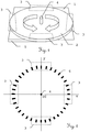
- Fig. 1 shows the schematic representation of the structural design of a generic protractor with a carrier element 1 with a rotating body 2 with a large number of pattern elements arranged around a pattern center, a detector arrangement of four optical detector elements 3.
- the disk-shaped rotating body 2 is arranged so as to be rotatable about an axis 4 relative to the carrier element 1 .
- the pattern elements are mapped onto the detector elements 3 of the detector arrangement.
- the positions of the pattern elements imaged on the detector arrangement are resolved and the rotational position and eccentricity of the pattern center relative to a detector center of the detector arrangement are derived.
- the eccentricity can be derived in several steps or directly in the course of determining the angle of rotation.
- three, four or more detector elements 2 are used. The measured eccentricity is not yet separated in terms of its different influencing variables in the context of the individual measurement.
- a large number of eccentricity measurements are carried out for different rotational positions of the rotating body 2. This can be done as a separate measurement or calibration pass and / or the measurement results can be recorded and used during operation. From the large number of eccentricity measurements, 5 different influencing variables of the current eccentricity are separated by a computing and evaluation unit, in particular by aggregate formation. The influencing variables can be saved or used for modeling and used in current or subsequent measurements as well as for mechanical or electronic corrections.
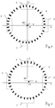
- Fig. 2 the schematic. Representation of the position of the rotating body without eccentricity error.
- the pattern elements 6 are shown, the pattern center of which in this case coincides with the axis of rotation 4.
- a detector center DZ can be defined for the detector arrangement consisting of the four detector elements 3, which ideally should coincide with the pattern center and the axis of rotation 4, so that no eccentricity errors occur.
- an x- and a y-axis can also be defined as reference values, with respect to which the rotational positions are determined.
- the code arranged on the rotating body is only made out For reasons of illustration, represented as an incremental code with an equidistant sequence of similar pattern elements 6.
- the method according to the invention is not limited to this and can in principle be used for all types of incremental or absolute codes.
- Fig. 3 the effect of the influencing variable of a code error is shown schematically.
- the pattern center MZ as the geometric center of the pattern elements 6 or the overall code defined by them is shifted to the top left.
- the pattern center executes a circular movement around the detector center DZ.
- the eccentricity of the sample center MZ can be compared to the Fig. 2 displaced positions of the pattern elements 6 on the detector elements 3 can be determined.
- the detector elements 3 register a degree of eccentricity that varies sinusoidally with the period 2 ⁇ depending on the rotational position.
- Fig. 4 shows the schematic representation of the effect of the influencing variables of a code error and a translational displacement of the axis of rotation.
- Pattern center MZ, detector center DZ and axis of rotation 4 now fall apart.
- the pattern center MZ moves in a circle around this axis of rotation 4, which in turn has an eccentricity with respect to the detector center DZ.
- the detector elements 3 of the detector arrangement always determine the position of the pattern elements 6 without a direct resolution of the influencing variables, from which the total eccentricity results.
- the detector elements 3 register an eccentricity dimension that is offset with respect to the axes and, depending on the rotational position, varies sinusoidally with the period 2 ⁇ .
- the position of the current pivot point of the rotating body with respect to the detector center DZ can be determined as a translational bearing shift.
- the time dependence can also be considered, for example by means of a continuous analysis during operation or an automatic calibration sequence over the full angular circle when the device is started. The values measured here can then be analyzed with regard to the change in the influencing variables with respect to time, and corresponding models or functions, for example for the change in the position of the current pivot point over time, can be derived.
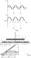
- Fig. 5 the separation of the influencing variables of a code error and a translational displacement of the axis of rotation is explained.
- the size of the eccentricity error ⁇ x with respect to the x-axis is shown as a function of the rotational position ⁇ .
- the upper illustration shows the change for the in Fig. 3 Pure code errors shown, ie the deviation of the pattern center from the pivot point, which in turn coincides with the detector center.
- the eccentricity error ⁇ x varies sinusoidally around the zero position, whereby for reasons of illustration also the Repetition of a rotation as a period until 4 ⁇ is shown.
- the lower illustration shows the change for the in Fig. 4 Combination of influences from code error and translational displacement of the axis of rotation, ie the deviation of the pattern center from the pivot point, and its deviation from the detector center.
- the eccentricity error ⁇ x varies sinusoidally around the zero position shifted by a non-periodic component NPA, the repetition of a rotation being represented here as a period up to 4 ⁇ for reasons of illustration.
- the position of the axis of rotation can be regarded as static for the purposes of the current determination. If the rotational positions are evenly distributed with a small number of measurements or the number of measurements is sufficiently large, the influences of the sinusoidal changes can be eliminated by averaging, in particular by a moving average, which also allows the values to be taken into account to be limited in time due to its detection window .
- General statistical approaches can be used in addition or as an alternative, e.g. a weighting of measurements based on their measurement time.
- the code or division error as a pattern-specific influencing variable with a periodicity corresponding to the full rotation of the rotating body can also be separated by other correspondingly suitable methods , for example by Fourier decomposition. This is useful, for example, if the measured values are noisy or not evenly distributed over the full circle. This also allows an analysis of variables that are not static within the measurement interval to be evaluated, such as a drifting, nutating or precessing axis of rotation, the harmonic components of which can be separated in this way.
- a supplement to the determination of influencing variables is the determination of vertical effects, ie taking the z-axis into account, as described in Fig. 6 is explained on the basis of the representation of the geometric relationships for determining the axial position of the rotating body 2.
- the position of the rotating body 2 or of pattern elements of the rotating body 2 in the axial direction is determined on the basis of the projection scale of the pattern elements onto the detector arrangement or the detector elements 3 by the computing and evaluation unit 5 arranged on the carrier element 1. If the detector arrangement has at least two detector elements 3, in particular with an orthogonal orientation, then a tilt of the axis of rotation 4 can be derived from the two distance values for the different position.
- the determination of the distance of the rotating body 2 to the detector element 3 or the detector arrangement is also possible independently of the other parts of the method, i.e. especially without the separation of the various influencing factors. This approach can therefore also be used independently of the method according to the invention.
Landscapes
- Physics & Mathematics (AREA)
- General Physics & Mathematics (AREA)
- Length Measuring Devices By Optical Means (AREA)
- Length Measuring Devices With Unspecified Measuring Means (AREA)
- Optical Transform (AREA)
Claims (9)
- Procédé de détermination d'au moins une grandeur d'influence sur l'excentricité dans un dispositif de mesure d'angle avec- un élément porteur (1) doté d'un arrangement de détecteur constitué d'au moins un élément détecteur optique (3), sous forme d'une tête goniométrique, de préférence trois ou quatre éléments détecteurs optiques (3), dans lequel l'arrangement de détecteur comporte un centre de détecteur (DZ) en tant qu'une position remarquable de l'arrangement de détecteur,- un corps tournant (2) doté d'une pluralité d'éléments de motif (6) agencés autour d'un centre de motif (MZ), dans lequel le corps tournant (2) est agencé contre l'élément porteur (1) en rotation autour d'un axe (4), et avec- une représentation d'au moins une partie des éléments de motif (6) sur l'arrangement de détecteur,- une résolution des positions des éléments de motif (6) représentés sur l'arrangement de détecteur,- une mesure de l'excentricité du centre de motif (MZ) par rapport au centre de détecteur (DZ),
caractérisé en ce que- une pluralité de mesures d'excentricité sont effectuées pour différentes positions de rotation et- au moins une grandeur d'influence de l'excentricité est séparée de la pluralité de mesures d'excentricité, en particulier par calcul d'agrégations. - Procédé selon la revendication 1,
caractérisé en ce que
les grandeurs d'influence de l'excentricité actuelle sont séparées par une décomposition de Fourier. - Procédé selon la revendication 1 ou 2,
caractérisé en ce que
une grandeur d'influence spécifique au motif avec une périodicité correspondant à la rotation complète du corps tournant (2) est séparée comme erreur de pas. - Procédé selon l'une des revendications précédentes,
caractérisé en ce que
une moyenne est formée à partir de la pluralité de mesures d'excentricité, en particulier une moyenne mobile. - Procédé selon l'une des revendications précédentes,
caractérisé en ce que
une position du point tournant actuel du corps tournant par rapport au centre de détecteur est déterminée comme déplacement de position translatoire. - Procédé selon la revendication 5,
caractérisé en ce que
la variation temporelle de la position du point tournant actuel est déterminée. - Procédé selon l'une des revendications précédentes,
caractérisé en ce que
la position du corps tournant (2) ou la position des éléments de motif (6) du corps tournant (2) dans la direction axiale est déterminée à l'aide de l'échelle de projection des éléments de motif (6) sur l'arrangement de détecteur. - Procédé selon la revendication 7,
caractérisé en ce que
la position des éléments de motif (6) du corps tournant (2) dans la direction axiale est déterminée sur l'arrangement de détecteur, dans lequel l'arrangement de détecteur comporte au moins deux éléments de détecteur, et un basculement de l'axe (4) est dérivé de la position. - Produit-programme informatique doté de code de programmation, enregistré sur un support lisible par machine ou est incarné par une onde porteuse électromagnétique, avec un segment de code informatique permettant de réaliser au moins une des étapes du procédé selon l'une des revendications 1 à 8.
Priority Applications (1)
| Application Number | Priority Date | Filing Date | Title |
|---|---|---|---|
| EP07847004.4A EP2108105B1 (fr) | 2007-01-09 | 2007-12-06 | Procédé de détermination d'une grandeur d'influence sur l'excentricité dans un dispositif de mesure d'angle |
Applications Claiming Priority (3)
| Application Number | Priority Date | Filing Date | Title |
|---|---|---|---|
| EP07100296A EP1944582A1 (fr) | 2007-01-09 | 2007-01-09 | Procédé de détermination d'une grandeur d'influence sur l'excentricité dans un dispositif de mesure d'angle |
| EP07847004.4A EP2108105B1 (fr) | 2007-01-09 | 2007-12-06 | Procédé de détermination d'une grandeur d'influence sur l'excentricité dans un dispositif de mesure d'angle |
| PCT/EP2007/010574 WO2008083797A1 (fr) | 2007-01-09 | 2007-12-06 | Procédé permettant de déterminer une grandeur d'influence agissant sur l'excentricité dans un goniomètre |
Publications (2)
| Publication Number | Publication Date |
|---|---|
| EP2108105A1 EP2108105A1 (fr) | 2009-10-14 |
| EP2108105B1 true EP2108105B1 (fr) | 2020-05-20 |
Family
ID=38283233
Family Applications (2)
| Application Number | Title | Priority Date | Filing Date |
|---|---|---|---|
| EP07100296A Withdrawn EP1944582A1 (fr) | 2007-01-09 | 2007-01-09 | Procédé de détermination d'une grandeur d'influence sur l'excentricité dans un dispositif de mesure d'angle |
| EP07847004.4A Active EP2108105B1 (fr) | 2007-01-09 | 2007-12-06 | Procédé de détermination d'une grandeur d'influence sur l'excentricité dans un dispositif de mesure d'angle |
Family Applications Before (1)
| Application Number | Title | Priority Date | Filing Date |
|---|---|---|---|
| EP07100296A Withdrawn EP1944582A1 (fr) | 2007-01-09 | 2007-01-09 | Procédé de détermination d'une grandeur d'influence sur l'excentricité dans un dispositif de mesure d'angle |
Country Status (7)
| Country | Link |
|---|---|
| US (1) | US8031334B2 (fr) |
| EP (2) | EP1944582A1 (fr) |
| CN (1) | CN101583851B (fr) |
| AU (1) | AU2007343360B2 (fr) |
| BR (1) | BRPI0720883B1 (fr) |
| CA (1) | CA2673857C (fr) |
| WO (1) | WO2008083797A1 (fr) |
Families Citing this family (20)
| Publication number | Priority date | Publication date | Assignee | Title |
|---|---|---|---|---|
| EP2163859A1 (fr) * | 2008-09-12 | 2010-03-17 | Leica Geosystems AG | Procédé et dispositif destinés à déterminer des positions |
| WO2011064317A2 (fr) | 2009-11-26 | 2011-06-03 | Leica Geosystems Ag | Procédé d'étalonnage et procédé de mesure angulaire pour un dispositif de mesure angulaire, ainsi que dispositif de mesure angulaire |
| EP2372302A1 (fr) * | 2010-03-26 | 2011-10-05 | Leica Geosystems AG | Procédé de mesure pour une machine de mesure mesurant les surfaces |
| JP2013526718A (ja) | 2010-05-17 | 2013-06-24 | ファロ テクノロジーズ インコーポレーテッド | 自己補償する角度エンコーダ |
| DE102010063521B4 (de) * | 2010-12-20 | 2013-07-18 | Siemens Aktiengesellschaft | Verfahren zum Ermitteln einer Lageänderung der Rotationsachse eines rotierenden Körpers innerhalb der Rotationsebene |
| EP2498076A1 (fr) | 2011-03-11 | 2012-09-12 | Hexagon Technology Center GmbH | Surveillance de l'usure d'une boîte de vitesse dans une centrale électrique |
| CN103827637B (zh) * | 2011-07-08 | 2016-02-24 | 卡尔蔡司工业测量技术有限公司 | 旋转装置的校准和运行、尤其是用于使坐标测量仪的探触头和/或探触件旋转的旋转装置的校准和运行 |
| WO2013007285A1 (fr) | 2011-07-08 | 2013-01-17 | Carl Zeiss Industrielle Messtechnik Gmbh | Correction et/ou prévention d'erreurs lors de la mesure de coordonnées d'une pièce |
| JP6055179B2 (ja) * | 2011-12-19 | 2016-12-27 | 株式会社トプコン | 回転角検出装置及び測量装置 |
| US9541382B2 (en) * | 2011-12-19 | 2017-01-10 | Kabushiki Kaisha Topcon | Rotation angle detecting apparatus and surveying instrument |
| DE102012207656A1 (de) * | 2012-05-08 | 2013-11-14 | Dr. Johannes Heidenhain Gmbh | Positionsmesseinrichtung und Verfahren zum Betreiben der Positionsmesseinrichtung |
| DE102012222997A1 (de) * | 2012-12-13 | 2014-07-03 | Siemens Aktiengesellschaft | Nichtdispersiver Infrarot-Gasanalysator |
| EP2824426B1 (fr) | 2013-07-09 | 2018-05-09 | Leica Geosystems AG | Capteur de rotation capacitif |
| DE102015201583B4 (de) | 2015-01-29 | 2018-07-26 | Carl Zeiss Industrielle Messtechnik Gmbh | Verfahren zur Ermittlung eines auf eine Drehvorrichtung einwirkenden Moments oder einer auf eine Drehvorrichtung einwirkenden Kraft |
| EP3139132B1 (fr) | 2015-09-03 | 2020-02-19 | Hexagon Technology Center GmbH | Codage absolu de surfaces |
| CN109737912B (zh) * | 2019-03-21 | 2021-04-02 | 博奥生物集团有限公司 | 一种偏心检测方法和偏心检测装置 |
| CN110030933B (zh) * | 2019-05-28 | 2020-04-28 | 杭州琼网计算机网络有限公司 | 基于电阻率变化原理的光学定心偏离检测装置 |
| CN110355610B (zh) * | 2019-05-28 | 2020-12-11 | 大连理工大学 | 一种螺旋铣孔装置的接触式实时偏心量检测方法 |
| CN110355609B (zh) * | 2019-05-28 | 2020-12-11 | 大连理工大学 | 一种螺旋铣孔装置的非接触式实时偏心量检测方法 |
| DE102024104438A1 (de) * | 2024-02-16 | 2025-08-21 | Carl Zeiss Smt Gmbh | Verfahren, Vorrichtung und Computerprogramm zum Bestimmen und Korrigieren eines Rundlauffehlers beim Drehen einer Probe |
Family Cites Families (7)
| Publication number | Priority date | Publication date | Assignee | Title |
|---|---|---|---|---|
| CH658514A5 (de) | 1982-02-09 | 1986-11-14 | Wild Heerbrugg Ag | Verfahren und vorrichtung zur erfassung einer messgroesse. |
| DE4401238C2 (de) * | 1994-01-18 | 1995-10-26 | Bmt Gmbh | Verfahren und Vorrichtung zur Vermessung von exzentrischen Teilen eines Meßobjekts |
| US6215119B1 (en) * | 1999-01-19 | 2001-04-10 | Xerox Corporation | Dual sensor encoder to counter eccentricity errors |
| DE19907326B4 (de) * | 1999-02-20 | 2013-04-04 | Dr. Johannes Heidenhain Gmbh | Winkelmeßsystem |
| JP4428781B2 (ja) * | 1999-12-28 | 2010-03-10 | キヤノン株式会社 | 光学式ロータリエンコーダ及びモータ制御装置 |
| JP4481137B2 (ja) * | 2003-11-13 | 2010-06-16 | アスモ株式会社 | モータ、回転制御装置、及び回転検出回路 |
| JP4938265B2 (ja) * | 2004-09-03 | 2012-05-23 | ライカ ジオシステムズ アクチェンゲゼルシャフト | 回転角を正確に測定する方法及び装置 |
-
2007
- 2007-01-09 EP EP07100296A patent/EP1944582A1/fr not_active Withdrawn
- 2007-12-06 US US12/522,198 patent/US8031334B2/en active Active
- 2007-12-06 AU AU2007343360A patent/AU2007343360B2/en not_active Ceased
- 2007-12-06 BR BRPI0720883-9A patent/BRPI0720883B1/pt not_active IP Right Cessation
- 2007-12-06 EP EP07847004.4A patent/EP2108105B1/fr active Active
- 2007-12-06 CN CN2007800495125A patent/CN101583851B/zh active Active
- 2007-12-06 CA CA2673857A patent/CA2673857C/fr not_active Expired - Fee Related
- 2007-12-06 WO PCT/EP2007/010574 patent/WO2008083797A1/fr not_active Ceased
Non-Patent Citations (1)
| Title |
|---|
| None * |
Also Published As
| Publication number | Publication date |
|---|---|
| EP1944582A1 (fr) | 2008-07-16 |
| AU2007343360A1 (en) | 2008-07-17 |
| CN101583851B (zh) | 2011-10-26 |
| AU2007343360B2 (en) | 2011-09-22 |
| WO2008083797A1 (fr) | 2008-07-17 |
| US8031334B2 (en) | 2011-10-04 |
| EP2108105A1 (fr) | 2009-10-14 |
| US20100039656A1 (en) | 2010-02-18 |
| BRPI0720883A2 (pt) | 2014-03-25 |
| WO2008083797A8 (fr) | 2009-11-12 |
| BRPI0720883B1 (pt) | 2019-05-14 |
| CA2673857C (fr) | 2013-04-02 |
| CN101583851A (zh) | 2009-11-18 |
| CA2673857A1 (fr) | 2008-07-17 |
Similar Documents
| Publication | Publication Date | Title |
|---|---|---|
| EP2108105B1 (fr) | Procédé de détermination d'une grandeur d'influence sur l'excentricité dans un dispositif de mesure d'angle | |
| EP2729768B1 (fr) | Calibrage et fonctionnement de dispositifs rotatifs, en particulier pour les têtes de détection et/ou les palpeurs des appareils de mesure de coordonnées | |
| EP2093537B1 (fr) | Système et procédé pour déterminer l'alignement de deux pièces de machine rotatives | |
| DE102012111008B4 (de) | Optisches Messverfahren und optische Messvorrichtung zum Erfassen einer Oberflächentopographie | |
| EP2834595B1 (fr) | Méthode et appareil pour la réduction des erreurs associées à un dispositif de rotation lors de la détermination des coordonnées d'une pièce ou lors de l'usinage d'une pièce | |
| EP2504666B1 (fr) | Procédé de calibrage et procédé de mesure d'angle pour un dispositif de mesure d'angle, ainsi que dispositif de mesure d'angle | |
| DE60311527T2 (de) | Werkstückinspektionsverfahren und vorrichtung | |
| DE2617707C2 (de) | Vorrichtung zum Vermessen einer Oberfläche | |
| EP0068082B1 (fr) | Procédé pour la mesure des déviations de la rondeur de corps rotation-symétriques | |
| EP2762832B1 (fr) | Mesure optique des points individuels | |
| DE102011011065B4 (de) | Verfahren und Vorrichtung zur hochpräzisen Vermessung von Oberflächen | |
| DE2429455A1 (de) | Elektro-optisches abtastsystem zum abmessen von abmessungen | |
| DE102015201583B4 (de) | Verfahren zur Ermittlung eines auf eine Drehvorrichtung einwirkenden Moments oder einer auf eine Drehvorrichtung einwirkenden Kraft | |
| EP2372302A1 (fr) | Procédé de mesure pour une machine de mesure mesurant les surfaces | |
| DE112006003663T5 (de) | Drehkodierer | |
| EP1923670A1 (fr) | Dispositif de mesure de position | |
| DE102014007201B4 (de) | Vorrichtung und Verfahren zur geometrischen Vermessung eines Objekts | |
| DE102004033600B4 (de) | Verfahren und Messanordnung zur Bestimmung der Topografie einer Oberfläche und Kalibriereinrichtung zur Kalibrierung einer derartigen Messanordnung | |
| EP2115695A1 (fr) | Procédé de détermination de la valeur d'un point de mesure, en particulier lors de la détermination de l'emplacement de contours, ainsi qu'appareil de mesure de précision optique | |
| DE4021793A1 (de) | Verfahren zur messung von winkeln und winkelkennlinien mit hilfe eines kreisels | |
| EP1724548B1 (fr) | Appareil de mesure de position | |
| DE19842190C1 (de) | Verfahren zur Bestimmung der Topographie von gekrümmten Oberflächen | |
| EP0479759B1 (fr) | Procédé et dispositif pour la mesure de longueurs ou d'angles | |
| EP0514726B1 (fr) | Méthode pour considérer, pendant l'équilibrage, la déviation de position des manetons de la bielle d'un vilebrequin et dispositif pour cela | |
| DE3441092C2 (de) | Verfahren und Vorrichtung zur kontinuierlichen Messung von Profilkurven und insbesondere von Unebenheitskurven |
Legal Events
| Date | Code | Title | Description |
|---|---|---|---|
| PUAI | Public reference made under article 153(3) epc to a published international application that has entered the european phase |
Free format text: ORIGINAL CODE: 0009012 |
|
| 17P | Request for examination filed |
Effective date: 20090604 |
|
| AK | Designated contracting states |
Kind code of ref document: A1 Designated state(s): AT BE BG CH CY CZ DE DK EE ES FI FR GB GR HU IE IS IT LI LT LU LV MC MT NL PL PT RO SE SI SK TR |
|
| RIN1 | Information on inventor provided before grant (corrected) |
Inventor name: AEBISCHER, BEAT Inventor name: SIERCKS, KNUT Inventor name: LIPPUNER, HEINZ |
|
| DAX | Request for extension of the european patent (deleted) | ||
| 17Q | First examination report despatched |
Effective date: 20160104 |
|
| GRAP | Despatch of communication of intention to grant a patent |
Free format text: ORIGINAL CODE: EPIDOSNIGR1 |
|
| STAA | Information on the status of an ep patent application or granted ep patent |
Free format text: STATUS: GRANT OF PATENT IS INTENDED |
|
| RIN1 | Information on inventor provided before grant (corrected) |
Inventor name: LIPPUNER, HEINZ Inventor name: AEBISCHER, BEAT Inventor name: SIERCKS, KNUT |
|
| INTG | Intention to grant announced |
Effective date: 20200211 |
|
| GRAS | Grant fee paid |
Free format text: ORIGINAL CODE: EPIDOSNIGR3 |
|
| GRAA | (expected) grant |
Free format text: ORIGINAL CODE: 0009210 |
|
| STAA | Information on the status of an ep patent application or granted ep patent |
Free format text: STATUS: THE PATENT HAS BEEN GRANTED |
|
| AK | Designated contracting states |
Kind code of ref document: B1 Designated state(s): AT BE BG CH CY CZ DE DK EE ES FI FR GB GR HU IE IS IT LI LT LU LV MC MT NL PL PT RO SE SI SK TR |
|
| REG | Reference to a national code |
Ref country code: GB Ref legal event code: FG4D Free format text: NOT ENGLISH |
|
| REG | Reference to a national code |
Ref country code: CH Ref legal event code: EP |
|
| REG | Reference to a national code |
Ref country code: DE Ref legal event code: R096 Ref document number: 502007016883 Country of ref document: DE |
|
| REG | Reference to a national code |
Ref country code: AT Ref legal event code: REF Ref document number: 1272889 Country of ref document: AT Kind code of ref document: T Effective date: 20200615 |
|
| REG | Reference to a national code |
Ref country code: LT Ref legal event code: MG4D |
|
| REG | Reference to a national code |
Ref country code: NL Ref legal event code: MP Effective date: 20200520 |
|
| PG25 | Lapsed in a contracting state [announced via postgrant information from national office to epo] |
Ref country code: PT Free format text: LAPSE BECAUSE OF FAILURE TO SUBMIT A TRANSLATION OF THE DESCRIPTION OR TO PAY THE FEE WITHIN THE PRESCRIBED TIME-LIMIT Effective date: 20200921 Ref country code: GR Free format text: LAPSE BECAUSE OF FAILURE TO SUBMIT A TRANSLATION OF THE DESCRIPTION OR TO PAY THE FEE WITHIN THE PRESCRIBED TIME-LIMIT Effective date: 20200821 Ref country code: IS Free format text: LAPSE BECAUSE OF FAILURE TO SUBMIT A TRANSLATION OF THE DESCRIPTION OR TO PAY THE FEE WITHIN THE PRESCRIBED TIME-LIMIT Effective date: 20200920 Ref country code: SE Free format text: LAPSE BECAUSE OF FAILURE TO SUBMIT A TRANSLATION OF THE DESCRIPTION OR TO PAY THE FEE WITHIN THE PRESCRIBED TIME-LIMIT Effective date: 20200520 Ref country code: LT Free format text: LAPSE BECAUSE OF FAILURE TO SUBMIT A TRANSLATION OF THE DESCRIPTION OR TO PAY THE FEE WITHIN THE PRESCRIBED TIME-LIMIT Effective date: 20200520 Ref country code: FI Free format text: LAPSE BECAUSE OF FAILURE TO SUBMIT A TRANSLATION OF THE DESCRIPTION OR TO PAY THE FEE WITHIN THE PRESCRIBED TIME-LIMIT Effective date: 20200520 |
|
| PG25 | Lapsed in a contracting state [announced via postgrant information from national office to epo] |
Ref country code: BG Free format text: LAPSE BECAUSE OF FAILURE TO SUBMIT A TRANSLATION OF THE DESCRIPTION OR TO PAY THE FEE WITHIN THE PRESCRIBED TIME-LIMIT Effective date: 20200820 Ref country code: LV Free format text: LAPSE BECAUSE OF FAILURE TO SUBMIT A TRANSLATION OF THE DESCRIPTION OR TO PAY THE FEE WITHIN THE PRESCRIBED TIME-LIMIT Effective date: 20200520 |
|
| PG25 | Lapsed in a contracting state [announced via postgrant information from national office to epo] |
Ref country code: NL Free format text: LAPSE BECAUSE OF FAILURE TO SUBMIT A TRANSLATION OF THE DESCRIPTION OR TO PAY THE FEE WITHIN THE PRESCRIBED TIME-LIMIT Effective date: 20200520 |
|
| PG25 | Lapsed in a contracting state [announced via postgrant information from national office to epo] |
Ref country code: RO Free format text: LAPSE BECAUSE OF FAILURE TO SUBMIT A TRANSLATION OF THE DESCRIPTION OR TO PAY THE FEE WITHIN THE PRESCRIBED TIME-LIMIT Effective date: 20200520 Ref country code: IT Free format text: LAPSE BECAUSE OF FAILURE TO SUBMIT A TRANSLATION OF THE DESCRIPTION OR TO PAY THE FEE WITHIN THE PRESCRIBED TIME-LIMIT Effective date: 20200520 Ref country code: DK Free format text: LAPSE BECAUSE OF FAILURE TO SUBMIT A TRANSLATION OF THE DESCRIPTION OR TO PAY THE FEE WITHIN THE PRESCRIBED TIME-LIMIT Effective date: 20200520 Ref country code: EE Free format text: LAPSE BECAUSE OF FAILURE TO SUBMIT A TRANSLATION OF THE DESCRIPTION OR TO PAY THE FEE WITHIN THE PRESCRIBED TIME-LIMIT Effective date: 20200520 Ref country code: ES Free format text: LAPSE BECAUSE OF FAILURE TO SUBMIT A TRANSLATION OF THE DESCRIPTION OR TO PAY THE FEE WITHIN THE PRESCRIBED TIME-LIMIT Effective date: 20200520 Ref country code: CZ Free format text: LAPSE BECAUSE OF FAILURE TO SUBMIT A TRANSLATION OF THE DESCRIPTION OR TO PAY THE FEE WITHIN THE PRESCRIBED TIME-LIMIT Effective date: 20200520 |
|
| REG | Reference to a national code |
Ref country code: DE Ref legal event code: R097 Ref document number: 502007016883 Country of ref document: DE |
|
| PG25 | Lapsed in a contracting state [announced via postgrant information from national office to epo] |
Ref country code: SK Free format text: LAPSE BECAUSE OF FAILURE TO SUBMIT A TRANSLATION OF THE DESCRIPTION OR TO PAY THE FEE WITHIN THE PRESCRIBED TIME-LIMIT Effective date: 20200520 Ref country code: PL Free format text: LAPSE BECAUSE OF FAILURE TO SUBMIT A TRANSLATION OF THE DESCRIPTION OR TO PAY THE FEE WITHIN THE PRESCRIBED TIME-LIMIT Effective date: 20200520 |
|
| PLBE | No opposition filed within time limit |
Free format text: ORIGINAL CODE: 0009261 |
|
| STAA | Information on the status of an ep patent application or granted ep patent |
Free format text: STATUS: NO OPPOSITION FILED WITHIN TIME LIMIT |
|
| 26N | No opposition filed |
Effective date: 20210223 |
|
| PG25 | Lapsed in a contracting state [announced via postgrant information from national office to epo] |
Ref country code: SI Free format text: LAPSE BECAUSE OF FAILURE TO SUBMIT A TRANSLATION OF THE DESCRIPTION OR TO PAY THE FEE WITHIN THE PRESCRIBED TIME-LIMIT Effective date: 20200520 |
|
| REG | Reference to a national code |
Ref country code: CH Ref legal event code: PL |
|
| GBPC | Gb: european patent ceased through non-payment of renewal fee |
Effective date: 20201206 |
|
| PG25 | Lapsed in a contracting state [announced via postgrant information from national office to epo] |
Ref country code: MC Free format text: LAPSE BECAUSE OF FAILURE TO SUBMIT A TRANSLATION OF THE DESCRIPTION OR TO PAY THE FEE WITHIN THE PRESCRIBED TIME-LIMIT Effective date: 20200520 |
|
| REG | Reference to a national code |
Ref country code: BE Ref legal event code: MM Effective date: 20201231 |
|
| PG25 | Lapsed in a contracting state [announced via postgrant information from national office to epo] |
Ref country code: LU Free format text: LAPSE BECAUSE OF NON-PAYMENT OF DUE FEES Effective date: 20201206 Ref country code: IE Free format text: LAPSE BECAUSE OF NON-PAYMENT OF DUE FEES Effective date: 20201206 |
|
| PG25 | Lapsed in a contracting state [announced via postgrant information from national office to epo] |
Ref country code: GB Free format text: LAPSE BECAUSE OF NON-PAYMENT OF DUE FEES Effective date: 20201206 Ref country code: CH Free format text: LAPSE BECAUSE OF NON-PAYMENT OF DUE FEES Effective date: 20201231 Ref country code: LI Free format text: LAPSE BECAUSE OF NON-PAYMENT OF DUE FEES Effective date: 20201231 |
|
| REG | Reference to a national code |
Ref country code: AT Ref legal event code: MM01 Ref document number: 1272889 Country of ref document: AT Kind code of ref document: T Effective date: 20201206 |
|
| PG25 | Lapsed in a contracting state [announced via postgrant information from national office to epo] |
Ref country code: AT Free format text: LAPSE BECAUSE OF NON-PAYMENT OF DUE FEES Effective date: 20201206 |
|
| PG25 | Lapsed in a contracting state [announced via postgrant information from national office to epo] |
Ref country code: TR Free format text: LAPSE BECAUSE OF FAILURE TO SUBMIT A TRANSLATION OF THE DESCRIPTION OR TO PAY THE FEE WITHIN THE PRESCRIBED TIME-LIMIT Effective date: 20200520 Ref country code: MT Free format text: LAPSE BECAUSE OF FAILURE TO SUBMIT A TRANSLATION OF THE DESCRIPTION OR TO PAY THE FEE WITHIN THE PRESCRIBED TIME-LIMIT Effective date: 20200520 Ref country code: CY Free format text: LAPSE BECAUSE OF FAILURE TO SUBMIT A TRANSLATION OF THE DESCRIPTION OR TO PAY THE FEE WITHIN THE PRESCRIBED TIME-LIMIT Effective date: 20200520 |
|
| PG25 | Lapsed in a contracting state [announced via postgrant information from national office to epo] |
Ref country code: BE Free format text: LAPSE BECAUSE OF NON-PAYMENT OF DUE FEES Effective date: 20201231 |
|
| PG25 | Lapsed in a contracting state [announced via postgrant information from national office to epo] |
Ref country code: IS Free format text: LAPSE BECAUSE OF NON-PAYMENT OF DUE FEES Effective date: 20200920 |
|
| PGFP | Annual fee paid to national office [announced via postgrant information from national office to epo] |
Ref country code: DE Payment date: 20251211 Year of fee payment: 19 |
|
| PGFP | Annual fee paid to national office [announced via postgrant information from national office to epo] |
Ref country code: FR Payment date: 20251222 Year of fee payment: 19 |