EP0068087A1 - Procédé pour l'évaporation sans nacelle - Google Patents
Procédé pour l'évaporation sans nacelle Download PDFInfo
- Publication number
- EP0068087A1 EP0068087A1 EP82102981A EP82102981A EP0068087A1 EP 0068087 A1 EP0068087 A1 EP 0068087A1 EP 82102981 A EP82102981 A EP 82102981A EP 82102981 A EP82102981 A EP 82102981A EP 0068087 A1 EP0068087 A1 EP 0068087A1
- Authority
- EP
- European Patent Office
- Prior art keywords
- wire
- supply
- heating
- boatless
- workpiece
- Prior art date
- Legal status (The legal status is an assumption and is not a legal conclusion. Google has not performed a legal analysis and makes no representation as to the accuracy of the status listed.)
- Granted
Links
- 238000001704 evaporation Methods 0.000 title claims abstract description 12
- 239000000463 material Substances 0.000 claims abstract description 16
- 238000000034 method Methods 0.000 claims abstract description 13
- 230000005499 meniscus Effects 0.000 claims abstract description 6
- 239000011248 coating agent Substances 0.000 claims abstract description 4
- 238000000576 coating method Methods 0.000 claims abstract description 4
- 238000010438 heat treatment Methods 0.000 claims description 12
- VYZAMTAEIAYCRO-UHFFFAOYSA-N Chromium Chemical compound [Cr] VYZAMTAEIAYCRO-UHFFFAOYSA-N 0.000 claims description 9
- 229910052804 chromium Inorganic materials 0.000 claims description 9
- 239000011651 chromium Substances 0.000 claims description 9
- RTAQQCXQSZGOHL-UHFFFAOYSA-N Titanium Chemical compound [Ti] RTAQQCXQSZGOHL-UHFFFAOYSA-N 0.000 claims description 8
- 229910052719 titanium Inorganic materials 0.000 claims description 6
- 239000010936 titanium Substances 0.000 claims description 6
- 230000006698 induction Effects 0.000 claims description 3
- 239000007787 solid Substances 0.000 claims 2
- 238000000151 deposition Methods 0.000 claims 1
- 239000012768 molten material Substances 0.000 claims 1
- 230000005855 radiation Effects 0.000 claims 1
- 230000008020 evaporation Effects 0.000 abstract description 8
- 230000001939 inductive effect Effects 0.000 abstract description 4
- 229910052751 metal Inorganic materials 0.000 description 9
- 239000002184 metal Substances 0.000 description 9
- 238000007740 vapor deposition Methods 0.000 description 8
- RYGMFSIKBFXOCR-UHFFFAOYSA-N Copper Chemical compound [Cu] RYGMFSIKBFXOCR-UHFFFAOYSA-N 0.000 description 4
- 229910052802 copper Inorganic materials 0.000 description 4
- 239000010949 copper Substances 0.000 description 4
- BQCADISMDOOEFD-UHFFFAOYSA-N Silver Chemical compound [Ag] BQCADISMDOOEFD-UHFFFAOYSA-N 0.000 description 3
- 229910052782 aluminium Inorganic materials 0.000 description 3
- XAGFODPZIPBFFR-UHFFFAOYSA-N aluminium Chemical compound [Al] XAGFODPZIPBFFR-UHFFFAOYSA-N 0.000 description 3
- 238000010894 electron beam technology Methods 0.000 description 3
- 150000002739 metals Chemical class 0.000 description 3
- 229910052709 silver Inorganic materials 0.000 description 3
- 239000004332 silver Substances 0.000 description 3
- 235000012431 wafers Nutrition 0.000 description 3
- PCHJSUWPFVWCPO-UHFFFAOYSA-N gold Chemical compound [Au] PCHJSUWPFVWCPO-UHFFFAOYSA-N 0.000 description 2
- 229910052737 gold Inorganic materials 0.000 description 2
- 239000010931 gold Substances 0.000 description 2
- 239000004065 semiconductor Substances 0.000 description 2
- 239000000758 substrate Substances 0.000 description 2
- 229910052715 tantalum Inorganic materials 0.000 description 2
- GUVRBAGPIYLISA-UHFFFAOYSA-N tantalum atom Chemical compound [Ta] GUVRBAGPIYLISA-UHFFFAOYSA-N 0.000 description 2
- WFKWXMTUELFFGS-UHFFFAOYSA-N tungsten Chemical compound [W] WFKWXMTUELFFGS-UHFFFAOYSA-N 0.000 description 2
- 229910052721 tungsten Inorganic materials 0.000 description 2
- 239000010937 tungsten Substances 0.000 description 2
- XLYOFNOQVPJJNP-UHFFFAOYSA-N water Substances O XLYOFNOQVPJJNP-UHFFFAOYSA-N 0.000 description 2
- ZOXJGFHDIHLPTG-UHFFFAOYSA-N Boron Chemical compound [B] ZOXJGFHDIHLPTG-UHFFFAOYSA-N 0.000 description 1
- ZOKXTWBITQBERF-UHFFFAOYSA-N Molybdenum Chemical compound [Mo] ZOKXTWBITQBERF-UHFFFAOYSA-N 0.000 description 1
- 230000015572 biosynthetic process Effects 0.000 description 1
- 229910052796 boron Inorganic materials 0.000 description 1
- 238000011109 contamination Methods 0.000 description 1
- 229910002804 graphite Inorganic materials 0.000 description 1
- 239000010439 graphite Substances 0.000 description 1
- 239000013528 metallic particle Substances 0.000 description 1
- 229910052750 molybdenum Inorganic materials 0.000 description 1
- 239000011733 molybdenum Substances 0.000 description 1
- MGRWKWACZDFZJT-UHFFFAOYSA-N molybdenum tungsten Chemical compound [Mo].[W] MGRWKWACZDFZJT-UHFFFAOYSA-N 0.000 description 1
- 230000000135 prohibitive effect Effects 0.000 description 1
- 238000005019 vapor deposition process Methods 0.000 description 1
Images

Classifications
-
- C—CHEMISTRY; METALLURGY
- C23—COATING METALLIC MATERIAL; COATING MATERIAL WITH METALLIC MATERIAL; CHEMICAL SURFACE TREATMENT; DIFFUSION TREATMENT OF METALLIC MATERIAL; COATING BY VACUUM EVAPORATION, BY SPUTTERING, BY ION IMPLANTATION OR BY CHEMICAL VAPOUR DEPOSITION, IN GENERAL; INHIBITING CORROSION OF METALLIC MATERIAL OR INCRUSTATION IN GENERAL
- C23C—COATING METALLIC MATERIAL; COATING MATERIAL WITH METALLIC MATERIAL; SURFACE TREATMENT OF METALLIC MATERIAL BY DIFFUSION INTO THE SURFACE, BY CHEMICAL CONVERSION OR SUBSTITUTION; COATING BY VACUUM EVAPORATION, BY SPUTTERING, BY ION IMPLANTATION OR BY CHEMICAL VAPOUR DEPOSITION, IN GENERAL
- C23C14/00—Coating by vacuum evaporation, by sputtering or by ion implantation of the coating forming material
- C23C14/22—Coating by vacuum evaporation, by sputtering or by ion implantation of the coating forming material characterised by the process of coating
- C23C14/24—Vacuum evaporation
Definitions
- This invention relates to vapor deposition and more particularly to a method and apparatus of evaporating a very reactive metal from a boatless point source.
- Reactive metals such as titanium, chromium and the like are frequently used in semiconductor devices and may be deposited by a vapor deposition process.
- Vapor deposition methods are described in van Amstel U. S. patent 3 499 785, Donckel U. S. patent 3 860 444, Anderson U. S. patent 4 061 800 and in the IBM Technical Disclosure Bulletin, Vol. 19, No. 7, March 1977, pp. 3852-53.
- These processes employ crucibles or boats of tantalum, tungsten-molybdenum, boron nitride-graphite or TiB 2 -A1 2 0 3 .
- These crucibles react with certain reactive metals such as chromium and titanium.
- Tungsten crucibles not only yield films containing traces of tungsten but they also only last for one or two runs before they fail.
- the invention intends to overcome the disadvantages discussed above.
- vapor deposition evaporating the end of a wire or rod made of that same material is used.
- the end of the wire is inductively or radiantly heated to form a molten convex meniscus thereon which serres as the coating source for the substrates.
- the wire may be chromium, titanium, aluminum, gold, silver, copper and the like.
- This vapor deposition method has a number of advantages over the prior art vapor deposition methods.
- One advantage is that there is no contamination of the deposited metal such as is common when crucibles or boats are used.
- Another advantage over the electron beam gun evaporation process is that there are no charge level problems caused by scattered electrons which build up on the workpiece.In addition, it is not necessary to break open a closed chamber and replace a boat or filament because the feed mechanism will feed the wire as required for an extended period of time.
- a feed mechanism 10 provides a metal wire 12 to move vertically so that the end 13 thereof may be heated by a heating means 14.
- a top view of a heater 14 is shown in Figure 2 where a resistance coil 15 surrounds the top 13 of the metal wire or rod 12.
- a side view of the resistance coil 15 and the wire 12 is shown in Figure 3.
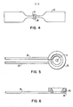
- the resistance coil 15 may also be in the form of a filament resistance strip 17 having an annular ring portion 19 surrounding the wire top 13 as shown in Figure 4.
- a radio-frequency (RF) coil 25 may be used as shown in Figures 5 and 6 to heat the top 13 inductively.
- the RF coil 25 is made of copper and silver coated for highest R.F. frequency.
- the connectors 28 and 30 join the coil 25 to the R.F. generator (not shown).
- the connectors 28 and 30 may be a continuous copper tube which is brazed to the induction coil 25.
- the metal wire or rod 12 is preferably chromium, titanium or aluminum, although other metals such as gold, silver, copper, tantalum and molybdenum may be used.
- spherical platform 18 may be rotated by motor 20 and detached therefrom by means of decoupler 22.
- the wire 12 and the substrates 16 are arranged in a closed vacuum chamber 23 so that the workpieces 16 are facing the top 13 of the wire 12 and within the vaporcloud cone 24 formed by the evaporation.
- the pressure in the chamber ranges from 10 mmHg to 10 -8 mmHg with the preferred range for chromium and titanium being 10 -6 to 10 8 mmH g.
- the inductive heater 14 is activated to inductively heat the end 13 of the wire 12 so that the metal is melted to form a molten spherical meniscus.
- the end 13 becomes molten, it finds its lowest energy formation, becomes spherical and stays on the wire. Enough heat is applied without increasing the molten mass so that the evaporation occurs from the spherical molten mass 13.
- any extraneous radiant heat generated by resistance heating can be minimized by using a water cooled shield (not shown).
- the addition of water cooled parabolic reflectors (not shown) about the wire end 13 focuses the radiant heat on the molten sphere 13.
- a chromium rod of 19.05 mm (0.750 inch) diameter was heated with a single turn RF coil by driving it with a 5 kW, 200-400 kHz, RF induction power supply.
- the vacuum chamber was then evacuated to a pressure of 10 -7 mmHg.
- Chromium was evaporated onto a wafer at a rate of 1 nm (10 R) per second when the wafer was positioned at a distance of 559 mm (22 inches) away. There was no expulsion of large metallic particles, that is "spitting" from the chromium source.
- Example 2 The process described in Example 1 was used with a titanium rod of 6.35 mm (0.250 inch) diameter. The evaporation rate of 0.1 to 0.2 nm (1-2 ⁇ ) per second at a distance of 559 mm (22 inches) was obtained.
- Example 1 The process described in Example 1 was used with an aluminum rod of 6.35 mm (0.25 inch) diameter. An evaporation rate of 0.5-0.6 nm (5-6 ⁇ ) per second at a distance of 559 mm (22 inches) was obtained.
Landscapes
- Chemical & Material Sciences (AREA)
- Chemical Kinetics & Catalysis (AREA)
- Engineering & Computer Science (AREA)
- Materials Engineering (AREA)
- Mechanical Engineering (AREA)
- Metallurgy (AREA)
- Organic Chemistry (AREA)
- Physical Vapour Deposition (AREA)
- Physical Deposition Of Substances That Are Components Of Semiconductor Devices (AREA)
Applications Claiming Priority (2)
| Application Number | Priority Date | Filing Date | Title |
|---|---|---|---|
| US278932 | 1981-06-30 | ||
| US06/278,932 US4390571A (en) | 1981-06-30 | 1981-06-30 | Boatless point source evaporation method |
Publications (2)
| Publication Number | Publication Date |
|---|---|
| EP0068087A1 true EP0068087A1 (fr) | 1983-01-05 |
| EP0068087B1 EP0068087B1 (fr) | 1986-10-15 |
Family
ID=23067001
Family Applications (1)
| Application Number | Title | Priority Date | Filing Date |
|---|---|---|---|
| EP82102981A Expired EP0068087B1 (fr) | 1981-06-30 | 1982-04-07 | Procédé pour l'évaporation sans nacelle |
Country Status (4)
| Country | Link |
|---|---|
| US (1) | US4390571A (fr) |
| EP (1) | EP0068087B1 (fr) |
| JP (1) | JPS6037869B2 (fr) |
| DE (1) | DE3273808D1 (fr) |
Cited By (3)
| Publication number | Priority date | Publication date | Assignee | Title |
|---|---|---|---|---|
| EP0154859A1 (fr) * | 1984-03-07 | 1985-09-18 | International Business Machines Corporation | Appareil pour le revêtement sous vide |
| EP0213556A3 (fr) * | 1985-08-23 | 1988-11-09 | Elektroschmelzwerk Kempten GmbH | Dispositif pour la vaporisation en continu de composés anorganiques au moyen d'une source de photons |
| WO2015158048A1 (fr) * | 2014-04-17 | 2015-10-22 | 京东方科技集团股份有限公司 | Dispositif d'évaporation sous vide |
Families Citing this family (4)
| Publication number | Priority date | Publication date | Assignee | Title |
|---|---|---|---|---|
| JPH0676607B2 (ja) * | 1986-09-02 | 1994-09-28 | 三井東圧化学株式会社 | 強磁性金属粉末の製造方法 |
| JP2005091345A (ja) * | 2003-08-13 | 2005-04-07 | Fuji Photo Film Co Ltd | 蒸着型蛍光体シートの製造方法および装置並びに蒸着型蛍光体シート |
| JP6488928B2 (ja) * | 2015-07-15 | 2019-03-27 | アイシン精機株式会社 | 蒸着装置 |
| JP2021505776A (ja) | 2017-12-06 | 2021-02-18 | アリゾナ・シン・フィルム・リサーチ・エルエルシー | 金属およびセラミック材料の付着のための付加製造のためのシステムおよび方法 |
Citations (2)
| Publication number | Priority date | Publication date | Assignee | Title |
|---|---|---|---|---|
| EP0018641A1 (fr) * | 1979-05-02 | 1980-11-12 | Optical Coating Laboratory, Inc. | Appareil pour le revêtement |
| US4263872A (en) * | 1980-01-31 | 1981-04-28 | Rca Corporation | Radiation heated reactor for chemical vapor deposition on substrates |
Family Cites Families (6)
| Publication number | Priority date | Publication date | Assignee | Title |
|---|---|---|---|---|
| NL6600179A (fr) * | 1966-01-07 | 1967-07-10 | ||
| BE795116A (fr) * | 1972-02-08 | 1973-05-29 | Cockerill | Procede d'alimentation de bain d'evaporation |
| US4061800A (en) * | 1975-02-06 | 1977-12-06 | Applied Materials, Inc. | Vapor desposition method |
| US4183975A (en) * | 1978-03-16 | 1980-01-15 | Dare Pafco, Inc. | Vacuum metallizing process |
| JPS5512100A (en) * | 1979-07-09 | 1980-01-28 | Shichifuku Shiyokuhin Kk | Egg tofu sealed container |
| US4406252A (en) * | 1980-12-29 | 1983-09-27 | Rockwell International Corporation | Inductive heating arrangement for evaporating thin film alloy onto a substrate |
-
1981
- 1981-06-30 US US06/278,932 patent/US4390571A/en not_active Expired - Lifetime
-
1982
- 1982-04-07 DE DE8282102981T patent/DE3273808D1/de not_active Expired
- 1982-04-07 EP EP82102981A patent/EP0068087B1/fr not_active Expired
- 1982-04-16 JP JP57062664A patent/JPS6037869B2/ja not_active Expired
Patent Citations (2)
| Publication number | Priority date | Publication date | Assignee | Title |
|---|---|---|---|---|
| EP0018641A1 (fr) * | 1979-05-02 | 1980-11-12 | Optical Coating Laboratory, Inc. | Appareil pour le revêtement |
| US4263872A (en) * | 1980-01-31 | 1981-04-28 | Rca Corporation | Radiation heated reactor for chemical vapor deposition on substrates |
Non-Patent Citations (2)
| Title |
|---|
| PATENT ABSTRACTS OF JAPAN, unexamined applications, C field, vol. 4, no. 124, September 2, 1980 THE PATENT OFFICE JAPANESE GOVERNMENT page 124 C 23 * |
| PATENT ABSTRACTS OF JAPAN, unexamined applications, C field, vol. 4, no. 85, June 18, 1980 THE PATENT OFFICE JAPANESE GOVERNMENT page 125 C 15 * |
Cited By (3)
| Publication number | Priority date | Publication date | Assignee | Title |
|---|---|---|---|---|
| EP0154859A1 (fr) * | 1984-03-07 | 1985-09-18 | International Business Machines Corporation | Appareil pour le revêtement sous vide |
| EP0213556A3 (fr) * | 1985-08-23 | 1988-11-09 | Elektroschmelzwerk Kempten GmbH | Dispositif pour la vaporisation en continu de composés anorganiques au moyen d'une source de photons |
| WO2015158048A1 (fr) * | 2014-04-17 | 2015-10-22 | 京东方科技集团股份有限公司 | Dispositif d'évaporation sous vide |
Also Published As
| Publication number | Publication date |
|---|---|
| DE3273808D1 (en) | 1986-11-20 |
| JPS6037869B2 (ja) | 1985-08-28 |
| US4390571A (en) | 1983-06-28 |
| JPS583971A (ja) | 1983-01-10 |
| EP0068087B1 (fr) | 1986-10-15 |
Similar Documents
| Publication | Publication Date | Title |
|---|---|---|
| US4505948A (en) | Method of coating ceramics and quartz crucibles with material electrically transformed into a vapor phase | |
| US2423729A (en) | Vaporization of substances in a vacuum | |
| US4412899A (en) | Cubic boron nitride preparation utilizing nitrogen gas | |
| US4871434A (en) | Process for equipment to coat tools for machining and forming techniques with mechanically resistant layers | |
| CA1157806A (fr) | Preparation de nitrure de bore cubique | |
| US2413606A (en) | Method of coating by evaporating metals | |
| US4390571A (en) | Boatless point source evaporation method | |
| JP2654375B2 (ja) | 蒸着方法 | |
| US2902574A (en) | Source for vapor deposition | |
| GB2156384A (en) | Apparatus for vapour deposition by arc discharge | |
| CA2476855C (fr) | Procede et dispositif destines a revetir un substrat | |
| US3420978A (en) | Pretreatment method for antiwettable materials | |
| WO1993024663A1 (fr) | Appareil et procede de production de revetements de carbure | |
| JPH09110412A (ja) | 酸化珪素の製造方法 | |
| GB2159540A (en) | Apparatus and methods for coating substrates | |
| US5441617A (en) | Anodic arc source containment mechanisms | |
| JP3404065B2 (ja) | 蒸着効率の高いイオンプレーティング装置 | |
| White | A survey of techniques for the vacuum deposition of thin metallic films | |
| JPS62235466A (ja) | 蒸着物質発生装置 | |
| JP2780494B2 (ja) | CVD法によるSi基板へのダイヤモンド膜形成方法 | |
| JP2634487B2 (ja) | イオンプレーティングによる耐摩耗性被膜形成法 | |
| JPS6338427B2 (fr) | ||
| GB2200654A (en) | Heating enhancement of resistive evaporation sources in ionisation assisted physical vapour deposition | |
| JPS6289872A (ja) | 固体被膜の析出形成装置 | |
| Craswell | An apparatus for use in coating a body with an evaporant |
Legal Events
| Date | Code | Title | Description |
|---|---|---|---|
| PUAI | Public reference made under article 153(3) epc to a published international application that has entered the european phase |
Free format text: ORIGINAL CODE: 0009012 |
|
| AK | Designated contracting states |
Designated state(s): DE FR GB |
|
| 17P | Request for examination filed |
Effective date: 19830420 |
|
| GRAA | (expected) grant |
Free format text: ORIGINAL CODE: 0009210 |
|
| AK | Designated contracting states |
Kind code of ref document: B1 Designated state(s): DE FR GB |
|
| REF | Corresponds to: |
Ref document number: 3273808 Country of ref document: DE Date of ref document: 19861120 |
|
| ET | Fr: translation filed | ||
| PLBE | No opposition filed within time limit |
Free format text: ORIGINAL CODE: 0009261 |
|
| STAA | Information on the status of an ep patent application or granted ep patent |
Free format text: STATUS: NO OPPOSITION FILED WITHIN TIME LIMIT |
|
| 26N | No opposition filed | ||
| PGFP | Annual fee paid to national office [announced via postgrant information from national office to epo] |
Ref country code: FR Payment date: 19920226 Year of fee payment: 11 |
|
| PGFP | Annual fee paid to national office [announced via postgrant information from national office to epo] |
Ref country code: GB Payment date: 19920304 Year of fee payment: 11 |
|
| PGFP | Annual fee paid to national office [announced via postgrant information from national office to epo] |
Ref country code: DE Payment date: 19920504 Year of fee payment: 11 |
|
| PG25 | Lapsed in a contracting state [announced via postgrant information from national office to epo] |
Ref country code: GB Effective date: 19930407 |
|
| GBPC | Gb: european patent ceased through non-payment of renewal fee |
Effective date: 19930407 |
|
| PG25 | Lapsed in a contracting state [announced via postgrant information from national office to epo] |
Ref country code: FR Effective date: 19931229 |
|
| PG25 | Lapsed in a contracting state [announced via postgrant information from national office to epo] |
Ref country code: DE Effective date: 19940101 |
|
| REG | Reference to a national code |
Ref country code: FR Ref legal event code: ST |