EP0068190B1 - Zum gleichzeitigen Entraffen, Glätten und Bremsen einer gerafften Schlauchhülle geeignete Vorrichtung - Google Patents
Zum gleichzeitigen Entraffen, Glätten und Bremsen einer gerafften Schlauchhülle geeignete Vorrichtung Download PDFInfo
- Publication number
- EP0068190B1 EP0068190B1 EP82104998A EP82104998A EP0068190B1 EP 0068190 B1 EP0068190 B1 EP 0068190B1 EP 82104998 A EP82104998 A EP 82104998A EP 82104998 A EP82104998 A EP 82104998A EP 0068190 B1 EP0068190 B1 EP 0068190B1
- Authority
- EP
- European Patent Office
- Prior art keywords
- tubular casing
- elements
- outer tube
- stuffing
- stuffing horn
- Prior art date
- Legal status (The legal status is an assumption and is not a legal conclusion. Google has not performed a legal analysis and makes no representation as to the accuracy of the status listed.)
- Expired
Links
- 235000013580 sausages Nutrition 0.000 claims abstract description 18
- 238000005520 cutting process Methods 0.000 claims abstract description 5
- 239000012530 fluid Substances 0.000 claims abstract 2
- 238000009499 grossing Methods 0.000 claims description 31
- 239000000463 material Substances 0.000 claims description 6
- 235000013372 meat Nutrition 0.000 claims description 2
- 239000000203 mixture Substances 0.000 abstract description 2
- 238000005429 filling process Methods 0.000 description 10
- 230000000694 effects Effects 0.000 description 5
- 229920002678 cellulose Polymers 0.000 description 4
- 239000001913 cellulose Substances 0.000 description 4
- 238000003825 pressing Methods 0.000 description 3
- XLYOFNOQVPJJNP-UHFFFAOYSA-N water Chemical compound O XLYOFNOQVPJJNP-UHFFFAOYSA-N 0.000 description 3
- PEDCQBHIVMGVHV-UHFFFAOYSA-N Glycerine Chemical compound OCC(O)CO PEDCQBHIVMGVHV-UHFFFAOYSA-N 0.000 description 2
- 230000009172 bursting Effects 0.000 description 2
- 238000006073 displacement reaction Methods 0.000 description 2
- 230000009969 flowable effect Effects 0.000 description 2
- 238000004519 manufacturing process Methods 0.000 description 2
- 102000008186 Collagen Human genes 0.000 description 1
- 108010035532 Collagen Proteins 0.000 description 1
- 239000004952 Polyamide Substances 0.000 description 1
- 229920000297 Rayon Polymers 0.000 description 1
- QVGXLLKOCUKJST-UHFFFAOYSA-N atomic oxygen Chemical compound [O] QVGXLLKOCUKJST-UHFFFAOYSA-N 0.000 description 1
- 239000003795 chemical substances by application Substances 0.000 description 1
- 230000001112 coagulating effect Effects 0.000 description 1
- 239000011248 coating agent Substances 0.000 description 1
- 238000000576 coating method Methods 0.000 description 1
- 229920001436 collagen Polymers 0.000 description 1
- 230000006835 compression Effects 0.000 description 1
- 238000007906 compression Methods 0.000 description 1
- 230000003111 delayed effect Effects 0.000 description 1
- 238000011161 development Methods 0.000 description 1
- 230000018109 developmental process Effects 0.000 description 1
- 239000013013 elastic material Substances 0.000 description 1
- 235000013305 food Nutrition 0.000 description 1
- 235000011187 glycerol Nutrition 0.000 description 1
- 210000000936 intestine Anatomy 0.000 description 1
- 235000013622 meat product Nutrition 0.000 description 1
- 239000002184 metal Substances 0.000 description 1
- 238000000034 method Methods 0.000 description 1
- 239000005445 natural material Substances 0.000 description 1
- 229910052760 oxygen Inorganic materials 0.000 description 1
- 239000001301 oxygen Substances 0.000 description 1
- 238000004806 packaging method and process Methods 0.000 description 1
- 235000011837 pasties Nutrition 0.000 description 1
- 239000004033 plastic Substances 0.000 description 1
- 239000004014 plasticizer Substances 0.000 description 1
- 229920002647 polyamide Polymers 0.000 description 1
- 229920000728 polyester Polymers 0.000 description 1
- 230000001172 regenerating effect Effects 0.000 description 1
- 230000001105 regulatory effect Effects 0.000 description 1
- 230000000284 resting effect Effects 0.000 description 1
- 239000011257 shell material Substances 0.000 description 1
Images

Classifications
-
- A—HUMAN NECESSITIES
- A22—BUTCHERING; MEAT TREATMENT; PROCESSING POULTRY OR FISH
- A22C—PROCESSING MEAT, POULTRY, OR FISH
- A22C11/00—Sausage making ; Apparatus for handling or conveying sausage products during manufacture
- A22C11/02—Sausage filling or stuffing machines
- A22C11/0245—Controlling devices
Definitions
- the invention relates to a device of the type mentioned in the preamble of claim 1.
- tubular casings For packaging food, e.g. Meat products in the form of sausage mass, are known to be gathered, tubular casings made of synthetic, semi-synthetic or natural material. These sleeves, also referred to in technical terms as “caterpillars” or “hollow bars”, are made from long sleeves by pleating and longitudinal axial compression, the length of the shirred sleeve usually being only 1 to 3% of the original length.
- a ruffled tubular casing which is closed on one side, is first pushed over the filling tube of a sausage filling machine to fill the sausage mixture. The sausage mass is then pressed under pressure through the filling tube into the casing, which is continuously drained thereby. After reaching a certain length, cylindrical sausages are tied and closed.
- the diameter of the sausages obtained should remain constant over the entire length for various reasons. Only a uniform diameter, the size of z. B. depends on the shell material, ensures an optimal filling process. There is also a risk of the sausage casing bursting when overfilled, while the sausage casing shows a wrinkled surface if the filling is too low.
- the casing is braked when it is pulled off the shirred part of the casing during the filling process by an additional device in the form of a ring with an annular shoulder arranged after the calibration disk, the braking effect being determined by the frictional force between the hose casing and the shoulder.
- This inelastic calibration disk has the disadvantage that, in the case of fluctuations in the circumference of the casing that cannot be avoided in terms of production technology, the casing is not optimally filled. If the caliber of the casing is too small, there is also the risk that it will be damaged or torn off by the calibration disk; at least there is a particularly strong friction between the casing and the calibration disk, so that the casing can be overfilled with sausage mass and, when brewed, tends not to withstand the bursting pressure and to burst.
- a calibration device is known (US-A-4 202 075), which consists of a flexible material and whose diameter can be varied. This device is also intended to stretch and widen the tubular casing before filling it with sausage mass, this device permitting a controllable expansion.
- strong frictional forces can also occur between the hose cover and the calibration part in this case.
- the hose casing is braked with a brake element arranged after the calibration device, which presses the hose casing against the filling pipe.
- the object of the present invention is to provide a device which is suitable for simultaneously detaching, smoothing and braking a shirred tubular casing before filling it with a stuffing device, the tubular casing being simultaneously easily braked from the shirred into one perfect wrinkle-free condition can be transferred without there being any risk that the hose cover will be damaged by the braking part or the calibration part during this process.
- the device is intended to include a brake part which enables a jerk-free removal, the risk of tearing off the hose casing being reduced.
- the maximum diameter of the hose when sliding over the elements that unravel, smooth and brake it is smaller than its outer diameter in the unraveled state, which was not predictable insofar as it was previously believed that the hose casing was spread and widened simultaneous unfolding and smoothing of the tubular casing is always necessary.
- annular hollow body has also been described, the maximum diameter of which is smaller than the inner diameter of the draped tubular casing (US Pat. No. 3,975,795).
- this known hollow body is only intended for smoothing the tubular casing, while a ring arranged in front of the annular hollow body, through the bore of which the tubular casing is pulled, is provided for unlocking.
- the tubular casing is not necessary for filling the tubular casing properly and is generally not of particular advantage. Rather, it is completely sufficient and, in the case of hoses with caliber fluctuations, is advantageous if the hose cover is pulled over the outside of the smoothing elements for simultaneous unrolling, smoothing and braking, without the hose cover having to be expanded beyond its original diameter, the maximum outside diameter being required the tubular casing is preferably 70 to 99%, in particular 90 to 99%, of its outside diameter in the un-gathered state.
- This maximum diameter is determined by the clear width of the stop cylinder which is essentially circular in cross section and against the cylindrical inner surface of which the outside of the tubular casing is pressed by the smoothing elements. Furthermore, the hose sleeve is braked with a single device, which at the same time has the function of unraveling and smoothing the hose sleeve, wherein the hose sleeve does not expand or stretch.
- An essential advantage of the device and the arrangement according to the invention is also that the tubular casing, in the already drained, wrinkle-free state, is pressed from the inside against the stop cylinder resting on its outside.
- the braking effect is achieved with a locally fixed stop cylinder due to the adjustable contact pressure of the smoothing elements inside the drained hose cover.
- the change in this contact pressure with which the smoothing elements press the tubular casing against the stop cylinder, and thus also the change in the braking effect can also be controlled during the filling process by displacing the first or second outer tube longitudinally and axially.
- the smoothing elements perform a pivoting movement in the direction or opposite direction to the stop cylinder. As the braking effect increases, the withdrawal of the tubular casing is delayed during the filling process and the filling caliber of the filled tubular casing becomes larger.
- the tubular casing consists, for example, of a material used for the production of sausages, such as cellulose hydrate, collagen or artificial intestine, e.g. B. made of polyamide or polyester, and is optionally fiber-reinforced, in particular with a paper insert. It may show a conventional coating on its outer and / or inner surface, e.g. B. from a water vapor and oxygen impermeable material, which is anchored, for example, with a conventional adhesion-promoting agent on the hose surface.
- a cellulose hydrate casing it can have a usual water content of e.g. 6 to 15%, but also have a very high water content, e.g. up to about 35%, so that it does not have to be watered before filling.
- Cellulose hydrate casings are usually made by coagulating viscose and regenerating the cellulose and contain plasticizers such as glycerin.
- Essential device parts according to the invention are the smoothing elements, which are arranged in the vicinity of the filling tube opening on the filling tube, and the stop cylinder, against which the smoothing elements can be pressed.
- the stuffing device is used for filling z. B. of sausage mass in tubular casings.
- the smoothing elements are preferably relatively rigid and are usually made of metal.
- the stop cylinder is fixed locally during the filling process. It can also consist of two or more individual segments, which together form a ring arranged around the filling tube, with distances possibly being present between individual adjacent segments. The shape and number of segments is then adapted to the smoothing elements.
- the inner surface of the stop i.e. its cylindrical inner surface is preferably made of elastic material, e.g. B. made of rubber, and shows a smooth surface so that the tubular casing is not damaged when pressed.
- the tubular casing After passing through the stop cylinder, the tubular casing is constricted by a ring directly at the filling tube opening, so that the sausage meat emerging from the filling tube opening cannot flow back towards the stop cylinder.
- Known devices for closing or tying the tubular casing e.g. B. clip devices, and a cutting station for separating the filled and sealed tube section.
- the unraveled start of the caterpillar is first pulled over the smoothing elements and closed in the clip device.
- the smoothing elements are pivoted as flat as possible onto the filling tube, in which one z. B. moves the second outer tube longitudinally axially in the opposite direction to the filling tube opening, and the stop cylinder either moved longitudinally axially to the filling tube or, if the stop cylinder consists of segments, the segments folded away from the filling tube.
- the casing As a result of the pressure with which the pasty filling material, for example sausage mass, is pressed through the filling pipe into the drained part of the tubular casing, the casing is continuously pushed over the outer one The surface of the smoothing elements is drawn, while at the same time it is unloaded and smoothed. As a result of the frictional forces caused by the mutual contact of the stop cylinder, hose and smoothing elements, the withdrawal of the hose cover is braked.
- the braking effect is not regulated by the extent of the expansion of the hose, but by the contact pressure between the smoothing elements and the stop cylinder, which is adjusted by moving the second outer tube, for example. This usually works with a take-off speed of 10 to 20 m / min.
- the smoothing elements are moved by longitudinally axial displacement e.g. of the second outer tube in the opposite direction to the filling tube opening again laid flat on the outer surface of the filling tube, the stop cylinder at least partially removed, for. B. by opening the segments of the stop cylinder or by moving the stop cylinder parallel to the filling tube longitudinal axis.
- the next shirred hose can then be applied to the filling tube.
- the longitudinal axial displacement z. B. the second outer tube can be done by hand or by mechanically, hydraulically or pneumatically acting devices.
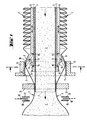
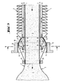
- FIG. 1 consists of the filling tube 1 of a filling device through which flowable mass 2 flows under pressure into the drained part 3 of the tubular casing.
- the gathered part 4 of the tubular casing is located on the second outer tube 6, which is arranged on the first outer tube 5 so as to be axially displaceable and lockable.
- the first outer tube 5 is detachably attached to a machine stand, not shown, and ends near the filling tube opening 7 in the form of a collar 8.
- the smoothing elements 9 are pivotally attached with their first surface end at the end of the second outer tube 6 via rotary bearings 10, while their outer Surface at the second surface end presses the tubular casing against the cylindrical inner surface 11 of the stop cylinder 12, which is designed as a brake lining.
- the smoothing elements 9 are also fixed at a distance from their first surface end via a pivot bearing 13 on couplers 14 which are fastened to a support bearing 15 on the collar 8 of the first outer tube 5.
- 16 and 17 schematically show clip devices for closing the sausage casings and 18 a cutting device.
- a device known per se for preventing the flowable mass from flowing back in the opposite direction to the hose travel is attached to the filling pipe opening 7. It has the shape of a ring 21 which constricts the hose.
- FIGS. 1 and 2 denotes the hose cover part from the entry into the pressing zone between smoothing elements 9 and cylindrical inner surface 11.
- the alternative shown in detail in FIG. 3 shows an additional plastic or rubber bellows 20, which is pressed against the cylindrical inner surface 11 of the stop cylinder 12 when the elements 9 are spread. It is attached to the collar 8 of the first outer tube 5 and at the end of the second outer tube 6.
- the clip devices 16, 17 and the cutting device 18 are not shown in FIG. 3.
- the device of the invention has the advantage that the shirred tubular casing 4 already runs into the friction area in a largely draped, wrinkle-free state 19, so that a smooth pull-off of the tubular casing is ensured during the filling process and the risk of tearing is greatly reduced.
- the filling caliber can be adjusted, corrected or controlled even during the filling process.
Landscapes
- Engineering & Computer Science (AREA)
- Life Sciences & Earth Sciences (AREA)
- Wood Science & Technology (AREA)
- Zoology (AREA)
- Food Science & Technology (AREA)
- Processing Of Meat And Fish (AREA)
- Containers And Plastic Fillers For Packaging (AREA)
- Buckles (AREA)
- Error Detection And Correction (AREA)
- Component Parts Of Construction Machinery (AREA)
- Chutes (AREA)
- Footwear And Its Accessory, Manufacturing Method And Apparatuses (AREA)
- Buildings Adapted To Withstand Abnormal External Influences (AREA)
- Automatic Assembly (AREA)
- Shaping By String And By Release Of Stress In Plastics And The Like (AREA)
- Processing And Handling Of Plastics And Other Materials For Molding In General (AREA)
Priority Applications (1)
| Application Number | Priority Date | Filing Date | Title |
|---|---|---|---|
| AT82104998T ATE18847T1 (de) | 1981-06-19 | 1982-06-08 | Zum gleichzeitigen entraffen, glaetten und bremsen einer gerafften schlauchhuelle geeignete vorrichtung. |
Applications Claiming Priority (2)
| Application Number | Priority Date | Filing Date | Title |
|---|---|---|---|
| DE19813124025 DE3124025A1 (de) | 1981-06-19 | 1981-06-19 | Zum gleichzeitigen entraffen, glaetten und bremsen einer gerafften schlauchhuelle geeignete vorrichtung sowie anordnung mit dieser vorrichtung |
| DE3124025 | 1981-06-19 |
Publications (2)
| Publication Number | Publication Date |
|---|---|
| EP0068190A1 EP0068190A1 (de) | 1983-01-05 |
| EP0068190B1 true EP0068190B1 (de) | 1986-04-02 |
Family
ID=6134878
Family Applications (1)
| Application Number | Title | Priority Date | Filing Date |
|---|---|---|---|
| EP82104998A Expired EP0068190B1 (de) | 1981-06-19 | 1982-06-08 | Zum gleichzeitigen Entraffen, Glätten und Bremsen einer gerafften Schlauchhülle geeignete Vorrichtung |
Country Status (7)
| Country | Link |
|---|---|
| US (1) | US4442568A (da) |
| EP (1) | EP0068190B1 (da) |
| AT (1) | ATE18847T1 (da) |
| CA (1) | CA1183315A (da) |
| DE (2) | DE3124025A1 (da) |
| DK (1) | DK154181C (da) |
| FI (1) | FI67771C (da) |
Families Citing this family (27)
| Publication number | Priority date | Publication date | Assignee | Title |
|---|---|---|---|---|
| DE3214673A1 (de) * | 1982-04-21 | 1983-10-27 | Hoechst Ag, 6230 Frankfurt | Vorrichtung zur herstellung von gefuellten schlauchhuellen |
| JPS5991834A (ja) * | 1982-11-17 | 1984-05-26 | 中村 實 | 食肉充填装置のためのシア−ドケ−シング送り出し装置 |
| DE3244085C1 (de) * | 1982-11-29 | 1984-03-22 | Günter 6080 Groß-Gerau Kollross | Verfahren und Vorrichtung zum OEffnen,axialen Raffen und Abtrennen von duennwandigem Schlauchhuellenmaterial und zum anschliessenden UEberfuehren der dadurch gebildeten Raupen an eine Weiterverarbeitungsstelle |
| JPS59130129A (ja) * | 1983-01-12 | 1984-07-26 | 中村 実 | 食肉充填装置 |
| US4521938A (en) * | 1983-06-23 | 1985-06-11 | Union Carbide Corporation | Casing sizing means, method and apparatus |
| US4512059A (en) * | 1983-08-09 | 1985-04-23 | Union Carbide Corporation | Casing sizing means and method |
| US4535508A (en) * | 1984-03-30 | 1985-08-20 | Union Carbide Corporation | Expandable casing sizing mechanism and method |
| US4675945A (en) * | 1985-01-23 | 1987-06-30 | Tipper Tie, Inc. | Clipping apparatus |
| US4646386A (en) * | 1985-04-18 | 1987-03-03 | Ilya Dreisin | Method of and apparatus for intermittently dispensing of filled products |
| US4766713A (en) * | 1987-07-27 | 1988-08-30 | Delaware Capital Formation, Inc. | Packaging device including dual clip attachment apparatus, a casing brake mechanism and gathering mechanism |
| US4847953A (en) * | 1988-09-29 | 1989-07-18 | Delaware Capital Formation, Inc. | Semi-automatic stuffing machine, casing brake and turret assembly |
| US4887332A (en) * | 1988-09-29 | 1989-12-19 | Delaware Capital Formation, Inc. | Semi-automatic stuffing machine, casing brake and turret assembly |
| US5042234A (en) * | 1989-05-17 | 1991-08-27 | Delaware Capital Formation Inc. | Collagen film and netting packaging system and method |
| US5109648A (en) * | 1989-05-19 | 1992-05-05 | Delaware Capital Formation, Inc. | Packaging device with loop attachment mechanism and skin brake |
| US5197914A (en) * | 1992-01-09 | 1993-03-30 | Marlen Research Corporation | Casing brake mechanism for stuffing apparatus |
| DE9211979U1 (de) * | 1992-09-05 | 1992-11-12 | Vemag Maschinenbau GmbH, 2810 Verden | Darmhaltevorrichtung |
| US5425221A (en) * | 1993-09-13 | 1995-06-20 | Pronovost; Normand | Apparatus for loading flexible tubing with bales |
| US5778642A (en) * | 1996-06-28 | 1998-07-14 | Free-Flow Packaging International, Inc. | System and method for use of loose fill packing materials |
| US6013295A (en) * | 1998-03-06 | 2000-01-11 | Townsend Engineering Company | Method for linking coextruded foodstuff |
| US6401885B1 (en) * | 2000-10-03 | 2002-06-11 | Tipper Tie, Inc. | Internal brake mechanism for plastic film for a product filling machine |
| US6745547B2 (en) * | 2002-05-06 | 2004-06-08 | Harry Bussey, Jr. | Cartridge for a bagging machine |
| US7520801B2 (en) * | 2005-05-24 | 2009-04-21 | Peter Parthenis | Variable geometry end-fitting for meat stuffer |
| ES2367870T3 (es) * | 2006-08-10 | 2011-11-10 | ALBERT HANDTMANN MASCHINENFABRIK GMBH & CO. KG | Freno de funda de embutido que puede ajustarse durante la producción. |
| DE102007020805A1 (de) * | 2007-05-03 | 2008-11-13 | Poly-Clip System Gmbh & Co. Kg | Darmbremse mit einstellbarer Bremskraft |
| ES2324274B1 (es) | 2009-02-05 | 2010-09-13 | Sagar Lorenzo Noguera | Dispositivo de freno para entrega de la tripa de embutidos en el extremo de tubos embutidores. |
| EA029594B1 (ru) * | 2016-02-04 | 2018-04-30 | Общество с ограниченной ответственностью "Машиностроительное предприятие "КОМПО" | Наполнительный узел |
| EA031859B1 (ru) * | 2016-09-01 | 2019-03-29 | Общество с ограниченной ответственностью "Машиностроительное предприятие "КОМПО" | Клипсатор |
Family Cites Families (8)
| Publication number | Priority date | Publication date | Assignee | Title |
|---|---|---|---|---|
| DE1177029B (de) * | 1959-01-07 | 1964-08-27 | Handtmann Albert | Fuellkopf fuer die Abdrehtuelle von Wurst-fuellmaschinen |
| DE1186359B (de) * | 1963-04-29 | 1965-01-28 | Handtmann Albert | Fuellkopf fuer die Abdrehtuelle von Wurstfuellmaschinen |
| US3457588A (en) * | 1966-12-05 | 1969-07-29 | Union Carbide Corp | Stuffing apparatus |
| US3975795A (en) * | 1975-01-20 | 1976-08-24 | Union Carbide Corporation | Product stuffing apparatus and method |
| US4077090A (en) * | 1976-05-14 | 1978-03-07 | Union Carbide Corporation | Food casing stuffing sizing control apparatus |
| DE2809385A1 (de) * | 1978-03-04 | 1979-09-06 | Hoechst Ag | Anordnung zum befuellen einer gerafften schlauchfoermigen huelle |
| US4317256A (en) * | 1980-01-16 | 1982-03-02 | Gunter Kollross | Expandable mandrel device for longitudinal shirring of flexible tubular material |
| US4335488A (en) * | 1980-08-25 | 1982-06-22 | Hoechst Aktiengesellschaft | Device for filling a shirred tubular casing |
-
1981
- 1981-06-19 DE DE19813124025 patent/DE3124025A1/de not_active Withdrawn
-
1982
- 1982-06-08 DE DE8282104998T patent/DE3270226D1/de not_active Expired
- 1982-06-08 AT AT82104998T patent/ATE18847T1/de not_active IP Right Cessation
- 1982-06-08 EP EP82104998A patent/EP0068190B1/de not_active Expired
- 1982-06-10 CA CA000404877A patent/CA1183315A/en not_active Expired
- 1982-06-11 US US06/387,370 patent/US4442568A/en not_active Expired - Fee Related
- 1982-06-17 FI FI822179A patent/FI67771C/fi not_active IP Right Cessation
- 1982-06-18 DK DK274482A patent/DK154181C/da active
Also Published As
| Publication number | Publication date |
|---|---|
| US4442568A (en) | 1984-04-17 |
| DE3124025A1 (de) | 1982-12-30 |
| FI822179A0 (fi) | 1982-06-17 |
| DK274482A (da) | 1982-12-20 |
| CA1183315A (en) | 1985-03-05 |
| EP0068190A1 (de) | 1983-01-05 |
| ATE18847T1 (de) | 1986-04-15 |
| FI822179L (fi) | 1982-12-20 |
| FI67771B (fi) | 1985-02-28 |
| DE3270226D1 (en) | 1986-05-07 |
| FI67771C (fi) | 1985-06-10 |
| DK154181C (da) | 1989-03-06 |
| DK154181B (da) | 1988-10-24 |
Similar Documents
| Publication | Publication Date | Title |
|---|---|---|
| EP0068190B1 (de) | Zum gleichzeitigen Entraffen, Glätten und Bremsen einer gerafften Schlauchhülle geeignete Vorrichtung | |
| EP0092131B1 (de) | Vorrichtung zur Herstellung von gefüllten Schlauchhüllen | |
| EP0070363B1 (de) | Zum gleichzeitigen Entfälteln, Glätten und Bremsen einer gerafften Schlauchhülle geeignete Vorrichtung | |
| EP0046560B1 (de) | Zum Entfälteln und Glätten einer gerafften Schlauchhülle geeignete Vorrichtung sowie diese Vorrichtung enthaltende Anordnung und funktionelle Einheit mit dieser Vorrichtung | |
| EP0004013B1 (de) | Anordnung zum Befüllen einer gerafften, schlauchförmigen Hülle | |
| DE2805351C2 (de) | Gerät zum Einsetzen in einen menschlichen Körperdurchgang | |
| DE2760303C2 (da) | ||
| DE2601595B2 (de) | Vorrichtung und Verfahren zum Stopfen von flexiblen Hüllen mit einem fließfähigen Vislosen Nahrungsmitelprodukt | |
| DE2648876A1 (de) | Vorverpackte geraffte schlauchfoermige wursthuelle | |
| DE1285908B (de) | Verfahren zum Kräuseln und Befeuchten von trockenen Wursthüllen | |
| DE1268011B (de) | Vorrichtung zum Raffen von feuchten Zelluloseschlaeuchen | |
| DE1532028B1 (de) | Verfahren und Vorrichtung zur Herstellung von gerafften Wursthuellen | |
| DE2024703A1 (de) | Verfahren und Vorrichtung für automatische Stopfmaschinen | |
| DE2317867A1 (de) | Stabfoermig geraffte schlauchfoermige nahrungsmittelhuelle | |
| EP0068342B1 (de) | Zum gleichzeitigen Entraffen, Glätten und Bremsen einer gerafften Schlauchhülle geeignete funktionelle Einheit | |
| EP2436268A1 (de) | Verfahren und Vorrichtung zur Herstellung einer Verpackungshülle für Lebensmittel | |
| EP0004620A1 (de) | Verfahren zum gleichzeitigen Befüllen und Wenden einer schlauchförmigen, aussenbeschichteten Verpackungshülle | |
| DE2511770C2 (de) | Balgartig geraffter und in ein Schlauchnetz eingeschlossener Kunstdarmschlauch | |
| EP1777161B1 (de) | Vorrichtung zum Verpacken von fließ-oder rieselfähigem Füllgut | |
| DE2612456A1 (de) | Stab aus geraffter kollagenhuelle mit einem endverschluss und verfahren zu dessen herstellung | |
| DE3214018A1 (de) | Verfahren zur herstellung von abgepackten fleischwaren und vorrichtung zur durchfuehrung des verfahrens | |
| DE2360480B2 (de) | Einseitig verschlossener Hohlstab aus geraffter Schlauchhülle mit innenliegendem, aus der Schlauchhülle selbst gebildetem Verschluß sowie Verfahren zur Herstellung des Verschlusses | |
| DE3401204C2 (da) | ||
| DE2952715A1 (de) | Verfahren und vorrichtung zum axialen raffen von duennwandigem aufgeblasenem schlauchmaterial, insbesondere fuer die wurstherstellung | |
| DE1143413B (de) | Abdrehtuelle fuer Vorrichtungen zum Einfuellen plastischer Massen, insbesondere von Wurstbraet, in Daerme, Schlaeuche od. dgl. |
Legal Events
| Date | Code | Title | Description |
|---|---|---|---|
| PUAI | Public reference made under article 153(3) epc to a published international application that has entered the european phase |
Free format text: ORIGINAL CODE: 0009012 |
|
| AK | Designated contracting states |
Designated state(s): AT BE CH DE FR GB IT LI LU NL SE |
|
| 17P | Request for examination filed |
Effective date: 19830610 |
|
| ITF | It: translation for a ep patent filed | ||
| GRAA | (expected) grant |
Free format text: ORIGINAL CODE: 0009210 |
|
| AK | Designated contracting states |
Kind code of ref document: B1 Designated state(s): AT BE CH DE FR GB IT LI LU NL SE |
|
| REF | Corresponds to: |
Ref document number: 18847 Country of ref document: AT Date of ref document: 19860415 Kind code of ref document: T |
|
| REF | Corresponds to: |
Ref document number: 3270226 Country of ref document: DE Date of ref document: 19860507 |
|
| ET | Fr: translation filed | ||
| PG25 | Lapsed in a contracting state [announced via postgrant information from national office to epo] |
Ref country code: LU Free format text: LAPSE BECAUSE OF NON-PAYMENT OF DUE FEES Effective date: 19860630 |
|
| PLBE | No opposition filed within time limit |
Free format text: ORIGINAL CODE: 0009261 |
|
| STAA | Information on the status of an ep patent application or granted ep patent |
Free format text: STATUS: NO OPPOSITION FILED WITHIN TIME LIMIT |
|
| 26N | No opposition filed | ||
| PGFP | Annual fee paid to national office [announced via postgrant information from national office to epo] |
Ref country code: FR Payment date: 19890512 Year of fee payment: 8 |
|
| PGFP | Annual fee paid to national office [announced via postgrant information from national office to epo] |
Ref country code: SE Payment date: 19890518 Year of fee payment: 8 |
|
| PGFP | Annual fee paid to national office [announced via postgrant information from national office to epo] |
Ref country code: LU Payment date: 19890524 Year of fee payment: 8 |
|
| PGFP | Annual fee paid to national office [announced via postgrant information from national office to epo] |
Ref country code: AT Payment date: 19890529 Year of fee payment: 8 |
|
| PGFP | Annual fee paid to national office [announced via postgrant information from national office to epo] |
Ref country code: GB Payment date: 19890531 Year of fee payment: 8 |
|
| PGFP | Annual fee paid to national office [announced via postgrant information from national office to epo] |
Ref country code: BE Payment date: 19890619 Year of fee payment: 8 |
|
| ITTA | It: last paid annual fee | ||
| PGFP | Annual fee paid to national office [announced via postgrant information from national office to epo] |
Ref country code: NL Payment date: 19890630 Year of fee payment: 8 |
|
| PGFP | Annual fee paid to national office [announced via postgrant information from national office to epo] |
Ref country code: CH Payment date: 19890821 Year of fee payment: 8 |
|
| PG25 | Lapsed in a contracting state [announced via postgrant information from national office to epo] |
Ref country code: DE Effective date: 19900301 |
|
| PG25 | Lapsed in a contracting state [announced via postgrant information from national office to epo] |
Ref country code: GB Effective date: 19900608 Ref country code: AT Effective date: 19900608 |
|
| PG25 | Lapsed in a contracting state [announced via postgrant information from national office to epo] |
Ref country code: SE Effective date: 19900609 |
|
| PG25 | Lapsed in a contracting state [announced via postgrant information from national office to epo] |
Ref country code: LI Effective date: 19900630 Ref country code: CH Effective date: 19900630 Ref country code: BE Effective date: 19900630 |
|
| BERE | Be: lapsed |
Owner name: HOECHST A.G. Effective date: 19900630 |
|
| PG25 | Lapsed in a contracting state [announced via postgrant information from national office to epo] |
Ref country code: NL Effective date: 19910101 |
|
| GBPC | Gb: european patent ceased through non-payment of renewal fee | ||
| NLV4 | Nl: lapsed or anulled due to non-payment of the annual fee | ||
| PG25 | Lapsed in a contracting state [announced via postgrant information from national office to epo] |
Ref country code: FR Effective date: 19910228 |
|
| REG | Reference to a national code |
Ref country code: CH Ref legal event code: PL |
|
| REG | Reference to a national code |
Ref country code: FR Ref legal event code: ST |
|
| EUG | Se: european patent has lapsed |
Ref document number: 82104998.8 Effective date: 19910206 |