EP0068503A2 - Méthode et dispositif d'essai de matériaux par le principe des courants de foucault - Google Patents
Méthode et dispositif d'essai de matériaux par le principe des courants de foucault Download PDFInfo
- Publication number
- EP0068503A2 EP0068503A2 EP82105819A EP82105819A EP0068503A2 EP 0068503 A2 EP0068503 A2 EP 0068503A2 EP 82105819 A EP82105819 A EP 82105819A EP 82105819 A EP82105819 A EP 82105819A EP 0068503 A2 EP0068503 A2 EP 0068503A2
- Authority
- EP
- European Patent Office
- Prior art keywords
- coil
- compensation
- amplifier
- variable
- real
- Prior art date
- Legal status (The legal status is an assumption and is not a legal conclusion. Google has not performed a legal analysis and makes no representation as to the accuracy of the status listed.)
- Granted
Links
- 238000000034 method Methods 0.000 title claims abstract description 16
- 238000012360 testing method Methods 0.000 title claims description 47
- 239000000463 material Substances 0.000 title claims description 6
- 238000005259 measurement Methods 0.000 claims abstract description 20
- 238000004154 testing of material Methods 0.000 claims abstract description 6
- 238000005070 sampling Methods 0.000 claims description 8
- 230000003321 amplification Effects 0.000 claims description 7
- 238000003199 nucleic acid amplification method Methods 0.000 claims description 7
- 230000007547 defect Effects 0.000 claims description 3
- 230000006870 function Effects 0.000 claims description 3
- 238000004088 simulation Methods 0.000 claims description 3
- 238000012937 correction Methods 0.000 claims description 2
- 238000011156 evaluation Methods 0.000 claims description 2
- 238000010998 test method Methods 0.000 claims 1
- 238000001514 detection method Methods 0.000 abstract description 5
- 230000002349 favourable effect Effects 0.000 abstract description 3
- 230000002452 interceptive effect Effects 0.000 abstract description 2
- 239000000523 sample Substances 0.000 description 9
- 238000010586 diagram Methods 0.000 description 3
- 230000000694 effects Effects 0.000 description 3
- 238000004364 calculation method Methods 0.000 description 2
- 239000000956 alloy Substances 0.000 description 1
- 229910045601 alloy Inorganic materials 0.000 description 1
- 238000006243 chemical reaction Methods 0.000 description 1
- 230000008878 coupling Effects 0.000 description 1
- 238000010168 coupling process Methods 0.000 description 1
- 238000005859 coupling reaction Methods 0.000 description 1
- 238000005530 etching Methods 0.000 description 1
- 238000012545 processing Methods 0.000 description 1
- 238000011160 research Methods 0.000 description 1
- 230000000717 retained effect Effects 0.000 description 1
- 238000000926 separation method Methods 0.000 description 1
- 238000007873 sieving Methods 0.000 description 1
- 239000004575 stone Substances 0.000 description 1
- 239000013589 supplement Substances 0.000 description 1
- 230000002123 temporal effect Effects 0.000 description 1
- 238000011144 upstream manufacturing Methods 0.000 description 1
Images


Classifications
-
- G—PHYSICS
- G01—MEASURING; TESTING
- G01N—INVESTIGATING OR ANALYSING MATERIALS BY DETERMINING THEIR CHEMICAL OR PHYSICAL PROPERTIES
- G01N27/00—Investigating or analysing materials by the use of electric, electrochemical, or magnetic means
- G01N27/72—Investigating or analysing materials by the use of electric, electrochemical, or magnetic means by investigating magnetic variables
- G01N27/82—Investigating or analysing materials by the use of electric, electrochemical, or magnetic means by investigating magnetic variables for investigating the presence of flaws
- G01N27/90—Investigating or analysing materials by the use of electric, electrochemical, or magnetic means by investigating magnetic variables for investigating the presence of flaws using eddy currents
- G01N27/9046—Investigating or analysing materials by the use of electric, electrochemical, or magnetic means by investigating magnetic variables for investigating the presence of flaws using eddy currents by analysing electrical signals
Definitions
- the invention relates to a method and an apparatus for material testing according to the eddy current principle, in which alternating magnetic fields are generated at a different frequency from a coil moving against a test specimen, which induce eddy currents in the test specimen, which are secondary in the coil or a feed spool Cause Fe! D, the output variable of the coil or sensor coil being broken down into its real and imaginary components.
- the output quantity is multiplied by the sine of the test signal.
- the second multiplier receives the cosine signa! fed.
- the multipliers are each followed by low-pass filters, to which compensation networks are connected, by means of which undesired test parameters are eliminated; while selected test parameters are retained.
- the invention is based on the object of developing a method and a pre-annihilation of the type described at the outset in such a way that, despite existing interference signals of low signal level, with a low-level SIgnai which triggers fault detection, the input amplifiers with low gain control at high amplification levels are avoided and the dynamic range is utilized as well as possible becomes.
- the object is achieved in that, depending on the output variable occurring at the respective frequency, a size is generated, which then becomes the output variable superimposed and an amplifier is fed to its operating point setting in the sense of optimal utilization of the dynamic range of the amplifier.
- the coil is arranged over a point of a test piece free from material defects, then the output size of the test piece is measured and the real and imaginary components are stored as reference values for the simulation of a test coil.
- the characteristic values typical for a reference coil are determined, which for subsequent measurement pr gears are available.
- the eddy may g ⁇ ngen absolute or Tastspul plante work without an additional coil is required for generating the reference levels then these Meßvor.
- a compensation amplifier having two inputs is arranged between the coil or the sensor coil and the amplifier, and that the amplifier having the variable gain has sample and hold circuits are connected, each of which is connected to a data bus via analog-digital converter, to the memory for the zero point correction, adding-subtracting units and inputs of an arithmetic unit, from which further inputs are connected to a control unit and to the control input of the amplifier has connected outputs and outputs connected to a vector generator, the output of which is connected to the second input of the compensation amplifier.
- the arithmetic unit there are in the arithmetic unit one register each for the storage of basic compensation values assigned to the real or imaginary part of the output variable and one register each for the storage of the real or inorganic part of the respective one.
- Measuring unit provided, the registers assigned to the real component: and the registers to the imaginary component: are each connected to adder / subtractor circuits, one each for the result Storage specific register is connected downstream, and wherein the outputs of these registers are connected to the inputs of the vector generator.
- the base compensation values can also include factors that are necessary to compensate for device-related errors.
- the outputs of the adding-subtracting units are preferably connected to the sieving unit.
- control unit contains a microcomputer with a data and a program memory.
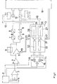
- a coil system 1 which can be an absolute, differential or probe coil, is connected to a coil driver 2, with which different frequencies are generated one after the other in time.
- the measuring coil which is not designated in any more detail, is connected with an output to a differential amplifier 3, the outputs of which feed an input of a compensation circuit 4 having two inputs.
- the compensation circuit 4 is a differential amplifier with a non-negating and a negating input.
- a further amplifier 5 is connected to the differential amplifier 4 and is intended for the main amplification.
- the amplifier 5 contains an optionally connectable feedback branch 6.
- the outputs of the amplifier 5 are connected to the inputs of two sample and hold circuits 7, each of which is followed by an analog-to-digital converter 8 via lines 9 ; st.
- the outputs of the analog-digital converter 8 are each connected to a data bus 10.
- Register 11 and inputs of arithmetic units 12 are also connected to the respective data bus 10.
- Each bus 10 also feeds parallel inputs of an arithmetic logic unit 13, which contains registers, adder / subtractor units and circuitry for squaring and etching, which are not described in more detail.
- Further inputs 17 of the arithmetic unit 13 are connected to a control unit 18, to which the outputs of the arithmetic units 12 are also connected.
- the arithmetic units 12 are add-subtract circuits.
- the amplifier 5 has control inputs 19 for changing the degree of amplification.
- the inputs 19 are connected to outputs 20 of the arithmetic unit 13, one of which is arranged in the arithmetic and logic unit 13, forming the square root of the sum of the squares of the input data.
- the control unit 18 contains a microcomputer, not shown, which is provided with a data and a program memory.
- the sample and hold circuits 7, the analog-to-digital converters 8, the registers 11 and the arithmetic units 12, like the arithmetic unit 13, operate under the control of the control unit 18. However, the corresponding control lines are not shown in FIG. 1.
- the arithmetic unit 13 contains registers 26 and 27, which are intended for storing the real part and the imaginary part of the respectively measured quantity.
- the registers 26 and 27 are fed by the analog-to-digital converters 8 via the downstream data bus lines.
- the function of registers 26, 27 is indicated by the designations AX and AY.
- the letters X and Y denote the real or imaginary part of the measured variable indicated by A.
- Two further registers 28, 29 of the arithmetic unit 13 are used to record basic compensation values.
- the registers 28, 29 are also each connected to a data bus 10.
- the basic compensation values are constant values belonging to each measurement, which also contain factors with which device-related measurement errors are compensated.
- the storage of constant compensation values is indicated in FIG. 1 on the registers 28, 29 by the letter K, while the assignment to the real or imaginary part is marked with X or Y.
- Each pair of registers 26, 28 or 27, 29 assigned to the real component or imaginary component is connected to an add-subtractor circuit 30 or 31. In the circuits 30, 31, the input values are added with no sign.
- The: Add i er subunit circuits 30, 31 are each followed by registers 32, 33, in which the result of the addition is stored. To identify their function, the registers 32, 33 in FIG. 1 are heated with AKN and AKY. The outputs of the registers 32, 33 feed inputs of the vector generator 14.
- the arrangement for calculating the square root of the sum of the squares of the input data which is present in the arithmetic logic unit 13 and is not shown in more detail, is fed by the registers 32 and 33.
- the inputs 17 are connected to the registers 32, 33.
- the registers 32, 33 can therefore optionally receive data from the circuits 30, 31 or from the control unit 18.
- the output variable of the coil system 1 is applied in analog form via the differential amplifier 3, the differential amplifier 4 and the main amplifier 5 to the inputs of the sample and hold circuits 7.
- the output signals of the amplifier 5 are broken down into their real and imaginary le by measuring the sine and cosine components at certain times.
- the real component and the imaginary component are each input into one of the sample and hold circuits 8. After conversion into digital values, the real component and the imaginary component are on a data bus 10 each.
- the registers 11 contain adjustment values that are subtracted from the current measured values before they are further processed by the control unit 18 by the one that is of interest. Separate parameters from the parameters of no interest.
- the output variables of the coil system 1 often contain high noise signal components, while the signal component relevant for the respective measurement of the test body properties has only a low level.
- FIG. 2a A useful signal 22 with a lower level is superimposed on an interference signal 21 with a high level.
- Interference signal levels of the type shown in Fig. 2a are caused, for example, by the lifting effect, by ferritic inclusions in the test specimen, etc. These interference signals are more pronounced than the useful signal 22 generated, for example, by a crack in the test specimen.
- the signal curve shown in FIG. 2a occurs, for example, at one of the frequencies intended for the test, to which certain frequency gates, ie time periods, are assigned.
- the arithmetic unit determines the level of the interference signal 21.
- the real component and the imaginary component of the interference signal are stored in the registers 26, 27 in the arithmetic and logic unit 13 and then added with correct constants with stored constants. These constants, which are typical for a specific measuring method, are entered into the registers 28, 29 of the arithmetic unit 13.
- the results of this processing of the peal portion on the imaginary portion are narrowed to the registers 32, 33 and passed as digital data to the inputs of the vector generator 14, at the output of which the compensation variable is generated. which is shown in Fig. 2b and designated 23.
- the temporal course of the compensation variable 23 corresponds approximately to that of the disturbance variable 21.
- the suppressed signal shown in FIG. 2c becomes the input of the amplifier 5 24 fed.
- the useful signal 22 is in turn superimposed on this suppressed signal.
- the useful / interference signal ratio in the course of the input signal of the amplifier 5 shown in FIG. 2c is considerably more favorable than in the case of the curve shown in FIG. 2a. Due to the superimposition between the output variable and the compensation variable, a favorable operating point of the amplifier 5 is reached. In addition, the risk of overdriving the amplifier 5 is avoided. After a clipping, the detection of crack signals would no longer be easy
- Digital compensation variables are accordingly obtained from the real and imaginary part of the interference signal. These compensation quantities or values which are proportional to these compensation quantities are quadriented and added up. By erasing this sum of the squares, a control variable is obtained for the control input 19 of the amplifier 5.
- the gain is set so high depending on the digital compensation variables that the dynamic range is optimally used for the signal levels at the coil output occurring during the measurement.
- a larger error signal value is determined via the sample and hold circuits 7 and the analog-digital converter 8. It steneg therefore for the digital values of the real and! Maginärantei! E more available to the analog-digital converters.
- the coil driver 2 generates four different frequencies in four time periods. These frequencies are shown as frequency gates along the abscissa axis of a coordinate system in FIG. 3, in the ordinate axis of which amplitudes are shown schematically.
- the frequency gates are labeled F1, F2, F3 and F4.
- the arithmetic and logic unit 13 receives a test value of the output variable of the coil system 1.
- the points in time of the specification of the test values are shifted approximately from the switch-on time of the respective frequency gate.
- the times of the practice of the sample values in the arithmetic unit for the different Freguenztore are designated with S F11 , S F21 , S F31 and S F41 .
- the calculation unit 13 determines the compensation variables which are decisive for the respective frequency and sets the degree of amplification of the amplifier 5 accordingly. Settling problems practically only occur with the shortest frequency tone. This can be 40 ⁇ sec, for example.
- the frequency gates F 1 , F 2 , F 3 , F 4 are short-lived.
- the measured values sampled at times S F11 , S F12 , S F21 etc. are therefore local! and practically invariant in time.
- the one in Flg. 2 course of the output variable shown is detected by means of several groups of frequency gates F 1 , F 2 , F 3 , F 4 .
- the sampling time S F12 results, for example, at a time 2 that occurs in a short time interval with reference to the duration of the curve shown in FIG. 2 the time t 1 follows.
- the duration of the frequency gates F 1 , F 2 , F 3 , F 4 and the sequence of the groups of frequency gates must be matched to the relative speed with which the coil 1 along the DUT is moved.
- a group of four frequency gates for example, can only claim rrsec, so that the relative movement between the coil and the test object occurring during the scanning is only slight. Influencing the measurement caused thereby is therefore reasonable
- the interference signal 21 has a maximum level of approximately 3 volts
- this is measured during the periods S F11 , S F12 , S F13 and S F14 with a tolerance of ⁇ 200 mV and processed in the arithmetic unit, which has a compensation variable and generates a setting value for the gain factor.
- the gain factor is set on the amplifier 5 and transmitted to the control unit 18.
- the control unit takes over the measured values and supplements the associated compensation value in the area of the higher digits of the data words.
- a reference coil can advantageously be simulated by the arithmetic unit 13 and the vector generator 14.
- the characteristic values typical of such a reference coil are stored in the arithmetic unit 13 and are applied to the inputs of the vector generator 14 during the measurement process. This will make operation of the Eddy current testers with absolute coils or probe coils possible without the need for an additional coil for the reference. Therefore, the high expenses that are required due to the strict requirements on the mechanical and technical constancy of the reference column are eliminated.
- the simulation of the reference coil by the arithmetic unit 13 and the vector generator 14 provides measurement values that are as precise as those obtained with a reference coil of high mechanical and trenmic constancy.
- the determination of the characteristic values takes place by measuring the output signal of the coil 1 over a surface point of the test object free of material defects.
- the output variable of this measurement broken down into the real and imaginary components, is stored in the control unit 18.
- the characteristic values serve as additional compensation values in the absolute or touch coil operating mode.
- the values obtained during the measurement of a test specimen which are very precise due to the large dynamic range, can be stored in the control unit 18, in particular in the memory of the microcomputer. These values are still available for subsequent measurements on test specimens. Therefore, confusion tests of the later measured data can be carried out using the values obtained first with a test body, the control unit 18 supplying the stored values to the connections 17 as reference values. It therefore make a very accurate comparison.
- control unit 18 It is also possible to store the measured values obtained during the measurement at the various locations on a test specimen in the control unit 18 or memory of the microcomputer. In the case of repeat tests, the control unit 18 likewise delivers the corresponding values to the inputs 17 of the arithmetic unit 13 as reference values. Therefore, the differences between different test specimens can be determined with high accuracy.
- the undesired error messages caused by such changes can be eliminated by the control unit 18 transmitting corresponding compensation values to the arithmetic unit 13 via the connections 17.
- the control unit 18 forms a delay element and outputs the compensation values c.rts and time-synchronously to the arithmetic unit 13, which uses the vector generator 14 to generate a compensation signal! generated with which the interfering signal components in the resuiting signal are eliminated.
Landscapes
- Chemical & Material Sciences (AREA)
- Chemical Kinetics & Catalysis (AREA)
- Electrochemistry (AREA)
- Physics & Mathematics (AREA)
- Health & Medical Sciences (AREA)
- Life Sciences & Earth Sciences (AREA)
- Analytical Chemistry (AREA)
- Biochemistry (AREA)
- General Health & Medical Sciences (AREA)
- General Physics & Mathematics (AREA)
- Immunology (AREA)
- Pathology (AREA)
- Investigating Or Analyzing Materials By The Use Of Magnetic Means (AREA)
Applications Claiming Priority (2)
| Application Number | Priority Date | Filing Date | Title |
|---|---|---|---|
| DE3125732 | 1981-06-30 | ||
| DE19813125732 DE3125732A1 (de) | 1981-06-30 | 1981-06-30 | Verfahren und vorrichtung zur werkstoffpruefung nach dem wirbelstromprinzip |
Publications (3)
| Publication Number | Publication Date |
|---|---|
| EP0068503A2 true EP0068503A2 (fr) | 1983-01-05 |
| EP0068503A3 EP0068503A3 (en) | 1983-10-05 |
| EP0068503B1 EP0068503B1 (fr) | 1987-03-25 |
Family
ID=6135748
Family Applications (1)
| Application Number | Title | Priority Date | Filing Date |
|---|---|---|---|
| EP82105819A Expired EP0068503B1 (fr) | 1981-06-30 | 1982-06-30 | Méthode et dispositif d'essai de matériaux par le principe des courants de foucault |
Country Status (5)
| Country | Link |
|---|---|
| US (1) | US4564809A (fr) |
| EP (1) | EP0068503B1 (fr) |
| JP (1) | JPS5832157A (fr) |
| CA (1) | CA1194548A (fr) |
| DE (1) | DE3125732A1 (fr) |
Cited By (4)
| Publication number | Priority date | Publication date | Assignee | Title |
|---|---|---|---|---|
| EP0092094A1 (fr) * | 1982-04-08 | 1983-10-26 | Nukem GmbH | Procédé et dispositif pour tester des matériaux selon le principe des courants de Foucault |
| GB2140564A (en) * | 1983-05-23 | 1984-11-28 | Central Electr Generat Board | Cable corrosion monitor |
| EP0122487A3 (en) * | 1983-04-16 | 1988-08-24 | Institut Dr. Friedrich Forster Prufgeratebau Gmbh & Co. Kg | Apparatus for testing the surfaces of metallic objects |
| EP0257603A3 (fr) * | 1986-08-27 | 1989-05-31 | Törnbloms Kvalitetskontroll Ab | Procédé d'essai à courants de Foucault d'objets non-magnétiques |
Families Citing this family (9)
| Publication number | Priority date | Publication date | Assignee | Title |
|---|---|---|---|---|
| DE3207569C2 (de) * | 1982-03-03 | 1986-05-28 | Herbert 8553 Ebermannstadt Baumgartner | Prüfgerät zur zerstörungsfreien Werkstoffprüfung |
| US4709213A (en) * | 1982-07-23 | 1987-11-24 | Garrett Electronics, Inc. | Metal detector having digital signal processing |
| DE3525376A1 (de) * | 1985-07-16 | 1987-01-29 | Nukem Gmbh | Verfahren und vorrichtung zur zerstoerungsfreien pruefung von ferromagnetischen koerpern mit oberflaechenabschnitten, die an kanten und/oder ecken aneinandergrenzen |
| DE3720686A1 (de) * | 1987-06-23 | 1989-01-05 | Foerster Inst Dr Friedrich | Verfahren zum untersuchen eines objektes |
| US5055784A (en) * | 1987-12-07 | 1991-10-08 | American Research Corporation Of Virginia | Bridgeless system for directly measuring complex impedance of an eddy current probe |
| CA2088918C (fr) * | 1991-06-04 | 1996-07-02 | Seigo Ando | Methode de detection magnetique et appareil utilise a cet effet |
| DE10229735A1 (de) * | 2002-07-02 | 2004-01-22 | rinas Gerätetechnik GmbH | Verfahren zum Erkennen und Lokalisieren von Materialfehlern |
| US9465008B2 (en) | 2014-06-13 | 2016-10-11 | General Electric Company | Method and system for eddy current device dynamic gain adjustment |
| CN108964811A (zh) * | 2018-06-07 | 2018-12-07 | 珠海格力电器股份有限公司 | 一种应变测试系统及方法 |
Family Cites Families (7)
| Publication number | Priority date | Publication date | Assignee | Title |
|---|---|---|---|---|
| US4194149A (en) * | 1977-12-15 | 1980-03-18 | The Babcock & Wilcox Company | Method for generating the eddy current signature of a flaw in a tube proximate a contiguous member which obscures the flaw signal |
| DE2814125C2 (de) * | 1978-04-01 | 1986-03-20 | Fraunhofer-Gesellschaft zur Förderung der angewandten Forschung e.V., 8000 München | Vorrichtung zur zerstörungsfreien Werkstoffprüfung |
| US4237419A (en) * | 1978-06-07 | 1980-12-02 | Tornbloms Kvalitetskontroll Ab | Method and apparatus for non-destructive testing using a plurality of frequencies |
| DE2825958C2 (de) * | 1978-06-14 | 1986-02-20 | Institut Dr. Friedrich Förster Prüfgerätebau GmbH & Co KG, 7410 Reutlingen | Magnetisches oder magnetinduktives Werkstoffprüfgerät mit Nullpunktkompensationseinrichtung |
| FR2443682A1 (fr) * | 1978-12-07 | 1980-07-04 | Commissariat Energie Atomique | Circuit de correction automatique d'un signal emis par un capteur differentiel desequilibre |
| FR2451032A1 (fr) * | 1979-03-09 | 1980-10-03 | Commissariat Energie Atomique | Appareil numerique pour le controle de pieces par courants de foucault |
| US4303885A (en) * | 1979-06-18 | 1981-12-01 | Electric Power Research Institute, Inc. | Digitally controlled multifrequency eddy current test apparatus and method |
-
1981
- 1981-06-30 DE DE19813125732 patent/DE3125732A1/de active Granted
-
1982
- 1982-06-22 US US06/390,964 patent/US4564809A/en not_active Expired - Fee Related
- 1982-06-23 CA CA000405838A patent/CA1194548A/fr not_active Expired
- 1982-06-30 EP EP82105819A patent/EP0068503B1/fr not_active Expired
- 1982-06-30 JP JP57111867A patent/JPS5832157A/ja active Pending
Cited By (5)
| Publication number | Priority date | Publication date | Assignee | Title |
|---|---|---|---|---|
| EP0092094A1 (fr) * | 1982-04-08 | 1983-10-26 | Nukem GmbH | Procédé et dispositif pour tester des matériaux selon le principe des courants de Foucault |
| EP0122487A3 (en) * | 1983-04-16 | 1988-08-24 | Institut Dr. Friedrich Forster Prufgeratebau Gmbh & Co. Kg | Apparatus for testing the surfaces of metallic objects |
| GB2140564A (en) * | 1983-05-23 | 1984-11-28 | Central Electr Generat Board | Cable corrosion monitor |
| US4652823A (en) * | 1983-05-23 | 1987-03-24 | Central Electricity Generating Board | Apparatus for and method of monitoring the corrosion in electrical power cables by measuring the variation in induced eddy currents |
| EP0257603A3 (fr) * | 1986-08-27 | 1989-05-31 | Törnbloms Kvalitetskontroll Ab | Procédé d'essai à courants de Foucault d'objets non-magnétiques |
Also Published As
| Publication number | Publication date |
|---|---|
| JPS5832157A (ja) | 1983-02-25 |
| CA1194548A (fr) | 1985-10-01 |
| DE3125732A1 (de) | 1983-01-13 |
| EP0068503A3 (en) | 1983-10-05 |
| DE3125732C2 (fr) | 1988-09-01 |
| EP0068503B1 (fr) | 1987-03-25 |
| US4564809A (en) | 1986-01-14 |
Similar Documents
| Publication | Publication Date | Title |
|---|---|---|
| DE19601707C2 (de) | Verfahren und Vorrichtung zum zerstörungsfreien Prüfen eines Drahtseiles | |
| DE3813739C2 (fr) | ||
| EP0287873B1 (fr) | Procédé pour mesurer et localiser avec précision des forces élastiques dans des domaines trempés d'éléments de construction | |
| DE3542159A1 (de) | Verfahren zur werkstoffpruefung nach dem wirbelstromprinzip und vorrichtung zur durchfuehrung des verfahrens | |
| EP0068503A2 (fr) | Méthode et dispositif d'essai de matériaux par le principe des courants de foucault | |
| DE102009022136A1 (de) | Vorrichtung und Verfahren für induktive Messungen | |
| DE2236959A1 (de) | Verfahren und vorrichtung zum testen des zustandes einer maschine | |
| DE102009022138A1 (de) | Vorrichtung und Verfahren für induktive Messungen | |
| EP0092094A1 (fr) | Procédé et dispositif pour tester des matériaux selon le principe des courants de Foucault | |
| DE69923366T2 (de) | Prüfsonde für elektromagnetische Strahlungsquellen und ihre Verwendung | |
| DE3525376C2 (fr) | ||
| DE19506339A1 (de) | Verfahren und Schaltungsvorrichtung zur elektromagnetischen Detektion von Objekten | |
| DE2701857A1 (de) | Messbruecke fuer vorrichtung zur werkstoffpruefung | |
| DE3586400T2 (de) | Verfahren und anordnung zum analysieren von geophonen. | |
| DE2952129A1 (de) | Vorrichtung zum testen und/oder messen elektrisch leitfaehiger, fester, fluessiger, oder pulverfoermiger materialien auf materialfehler, materialveraenderungen oder aenderung ihrer elektrischen eigenschaften | |
| DE3446867C2 (de) | Vorrichtung zur zerstörungsfreien Prüfung längsverschiebbarer ferromagnetischer Körper und Verfahren zur Einstellung der Vorrichtung in einen auf die jeweiligen Prüflinge abgestimmten Ausgangszustand für die Prüfung | |
| DE2817625A1 (de) | Verfahren und anordnung zur ermittlung von fehlern oder schaeden an beweglichen maschinenteilen vor allem in lagern | |
| DE4133619C2 (de) | Verfahren und Vorrichtung zur Messung des Einschwingverhaltens | |
| DE2612253A1 (de) | Verfahren und vorrichtung zur bestimmung des vulkanisationsverlaufs von kautschuk und die reaktionskinetische auswertung von vulkametrisch ermittelten vernetzungsisothermen | |
| EP0919819B1 (fr) | Procédé et appareil pour evaluation des signaux de mesure | |
| DE3308717A1 (de) | Vorrichtung zum ausmessen von magnetfeldern | |
| DE2646827A1 (de) | Zugpruefung von gummi | |
| DE102022131695A1 (de) | Verfahren zum Korrigieren einer Messgröße oder Messen eines Qualitätsparameters eines durch ein Messrohr strömendes Medium und ein Messgerät zur Durchführung des Verfahrens | |
| DE19940843A1 (de) | Bestimmung des elektrischen Widerstandes eines Materials mittels Wirbelstromverfahren | |
| DE4011588A1 (de) | Verfahren zur zerstoerungsfreien ermittlung mehrerer parameter der mechanischen beschaffenheit metallischer werkstoffe und einrichtung zur durchfuehrung dieses verfahrens |
Legal Events
| Date | Code | Title | Description |
|---|---|---|---|
| PUAI | Public reference made under article 153(3) epc to a published international application that has entered the european phase |
Free format text: ORIGINAL CODE: 0009012 |
|
| AK | Designated contracting states |
Designated state(s): BE FR IT SE |
|
| PUAL | Search report despatched |
Free format text: ORIGINAL CODE: 0009013 |
|
| AK | Designated contracting states |
Designated state(s): BE FR IT SE |
|
| 17P | Request for examination filed |
Effective date: 19840224 |
|
| GRAA | (expected) grant |
Free format text: ORIGINAL CODE: 0009210 |
|
| AK | Designated contracting states |
Kind code of ref document: B1 Designated state(s): BE FR IT SE |
|
| ITF | It: translation for a ep patent filed | ||
| ET | Fr: translation filed | ||
| PLBI | Opposition filed |
Free format text: ORIGINAL CODE: 0009260 |
|
| 26 | Opposition filed |
Opponent name: ASEA AKTIEBOLAG Effective date: 19871222 |
|
| PGFP | Annual fee paid to national office [announced via postgrant information from national office to epo] |
Ref country code: SE Payment date: 19900615 Year of fee payment: 9 |
|
| PGFP | Annual fee paid to national office [announced via postgrant information from national office to epo] |
Ref country code: FR Payment date: 19900629 Year of fee payment: 9 Ref country code: BE Payment date: 19900629 Year of fee payment: 9 |
|
| ITTA | It: last paid annual fee | ||
| RDAG | Patent revoked |
Free format text: ORIGINAL CODE: 0009271 |
|
| STAA | Information on the status of an ep patent application or granted ep patent |
Free format text: STATUS: PATENT REVOKED |
|
| 27W | Patent revoked |
Effective date: 19900719 |
|
| BERE | Be: lapsed |
Owner name: NUKEM G.M.B.H. Effective date: 19910630 |
|
| EUG | Se: european patent has lapsed |
Ref document number: 82105819.5 Effective date: 19901114 |
|
| APAH | Appeal reference modified |
Free format text: ORIGINAL CODE: EPIDOSCREFNO |