EP0092094A1 - Procédé et dispositif pour tester des matériaux selon le principe des courants de Foucault - Google Patents
Procédé et dispositif pour tester des matériaux selon le principe des courants de Foucault Download PDFInfo
- Publication number
- EP0092094A1 EP0092094A1 EP83103286A EP83103286A EP0092094A1 EP 0092094 A1 EP0092094 A1 EP 0092094A1 EP 83103286 A EP83103286 A EP 83103286A EP 83103286 A EP83103286 A EP 83103286A EP 0092094 A1 EP0092094 A1 EP 0092094A1
- Authority
- EP
- European Patent Office
- Prior art keywords
- measured values
- signals
- error
- fault
- memory
- Prior art date
- Legal status (The legal status is an assumption and is not a legal conclusion. Google has not performed a legal analysis and makes no representation as to the accuracy of the status listed.)
- Granted
Links
- 238000012360 testing method Methods 0.000 title claims abstract description 42
- 238000000034 method Methods 0.000 title claims abstract description 20
- 239000000463 material Substances 0.000 claims abstract description 13
- 230000015654 memory Effects 0.000 claims description 62
- 238000005259 measurement Methods 0.000 claims description 10
- 230000001629 suppression Effects 0.000 claims description 5
- 238000011156 evaluation Methods 0.000 claims description 4
- 230000007704 transition Effects 0.000 claims description 4
- 238000012545 processing Methods 0.000 abstract description 9
- 230000035945 sensitivity Effects 0.000 abstract description 4
- 230000008030 elimination Effects 0.000 abstract 1
- 238000003379 elimination reaction Methods 0.000 abstract 1
- 230000002452 interceptive effect Effects 0.000 description 9
- 230000000694 effects Effects 0.000 description 4
- 230000007547 defect Effects 0.000 description 3
- 238000001514 detection method Methods 0.000 description 3
- 238000005070 sampling Methods 0.000 description 3
- 230000008569 process Effects 0.000 description 2
- 230000004913 activation Effects 0.000 description 1
- 230000008859 change Effects 0.000 description 1
- 238000011161 development Methods 0.000 description 1
- 230000018109 developmental process Effects 0.000 description 1
- 238000010586 diagram Methods 0.000 description 1
- 239000011159 matrix material Substances 0.000 description 1
- 230000004044 response Effects 0.000 description 1
- 238000000926 separation method Methods 0.000 description 1
- 238000004154 testing of material Methods 0.000 description 1
Images

Classifications
-
- G—PHYSICS
- G01—MEASURING; TESTING
- G01N—INVESTIGATING OR ANALYSING MATERIALS BY DETERMINING THEIR CHEMICAL OR PHYSICAL PROPERTIES
- G01N27/00—Investigating or analysing materials by the use of electric, electrochemical, or magnetic means
- G01N27/72—Investigating or analysing materials by the use of electric, electrochemical, or magnetic means by investigating magnetic variables
- G01N27/82—Investigating or analysing materials by the use of electric, electrochemical, or magnetic means by investigating magnetic variables for investigating the presence of flaws
- G01N27/90—Investigating or analysing materials by the use of electric, electrochemical, or magnetic means by investigating magnetic variables for investigating the presence of flaws using eddy currents
- G01N27/9046—Investigating or analysing materials by the use of electric, electrochemical, or magnetic means by investigating magnetic variables for investigating the presence of flaws using eddy currents by analysing electrical signals
Definitions
- the invention relates to a method and an apparatus for testing materials according to the eddy current principle with a coil moving relative to a test specimen, with which eddy currents are induced in the test specimen by alternating magnetic fields, which cause a secondary field in "the coil or a sensor coil, whereby the signals occurring at the output of the coil or sensor coil during a scanning cycle are converted into a sequence of digital values corresponding to complex numbers.
- Linear algorithms are used in multi-frequency test equipment to distinguish between error and interference signals. Stationary, independent measured values at different measuring frequencies are linked to one another by matrix operations in order to generate zeros in interference devices to be suppressed. Error signals are only displayed if they fall in phase in other areas and with greater amplitude, the larger the phase angle in relation to the interference. If the error size affects not only the amplitude but also the phase position, this results in losses which have an unfavorable effect on the error size determination. These losses occur regardless of whether an interferer signal coincides with an error signal or not.
- the invention is based on the object of further developing a method of the type described in the introduction in such a way that the detection of interference signals takes place in a separate step with simultaneous storage of the complex measured values generated in the respective test cycle, which then, depending on the detection of interference signals, with or without compensation the influence of the interference signals are processed further.
- the object is achieved in that the complex measured values of the respective sequence are stored one after the other, that the individual measured values are checked, depending on their sequence, to determine whether they lie within test object-related limits in areas which differ from the measured values of a sequence only in the case of Fault signals, in the case of fault signals in connection with fault signals or only in the case of fault signals, are run through in a predetermined order and that the measured values in the case of fault signals in connection with fault signals after suppression of fault signals and in the case of fault signals without connection to fault signals are used directly to determine the type of fault and then to determine it the error size can be evaluated. If there are no interference signals occur with this method, the measuring sensitivity present in an eddy current device can be fully utilized for the determination of the type and size of material defects.
- interference signals are detected together with error signals, the influence of the interference can be suppressed.
- the type and size of material defects is detected with less sensitivity after suppression of the interferer signal. It has been shown that the examination of the complex measured values with regard to their position in the specified areas and with regard to the sequence of the transition to other areas can be used to assess whether there is only one fault signal or only one fault signal or one fault signal in connection with a fault signal .
- the sequence from an area that is only assigned to error signals to an area that is assigned to both fault signals and error signals, and when the complex measured values are transferred from the area, an error message is generated in the area that is assigned to both error signals and error signals.
- the location of successive complex measured values in the different areas is used here as a criterion in order to determine the presence of material defects in a simple manner.
- the position and sequence in the areas are preferably checked with about ten to fifteen complex measured values, these measured values being stored for the subsequent evaluation at the same time. This number of measured values is sufficient for deciding on fault signals and error signals and for subsequent processing with regard to the type and size of the error.
- an area center point is specified which is at a uniform distance from is surrounded by a basic threshold which excludes complex measurement values lying within its limits from the evaluation.
- the size of the basic threshold depends on the sensitivity of the measurement and the size of the processed signals.
- an apparatus for carrying out the methods described above consists in that an eddy current test device is connected via a data channel to a FIFO memory and to a further memory, in which information about the affiliation of the respective measured value is given under addresses which correspond to the complex measured values a predetermined range is contained in that the further memories are followed by registers for storing the memory output signals which occur in the case of adjacent measured values, which are checked by a comparator for range transitions, that a further register and logic elements for determining the ranges traversed by the measured values in a predetermined sequence are connected downstream of the memories and that the output signals of the comparator and of the logic elements are connected to a microcomputer, by means of which the control of memories for the definition of the type of error and a memory for the error level is carried out window detection and an output channel for marking and sorting devices is controllable. With this device it can be determined within a short time whether there is an error and what type of error is. It is therefore possible to take precautions for the placement of a sorting gate
- a coil (not shown), which is moved relative to a test specimen, generates alternating magnetic fields in the test specimen, for example with different frequencies.
- the alternating fields induce eddy currents which cause a secondary field in a sensor coil or in the coil switched to receive.
- the output signals of the coil or sensor coil can be broken down into their real and imaginary components, which are converted into digital values.
- This results in a series of measured values per measurement cycle which can be represented in a Cartesian coordinate system, in the abscissa direction of which, for example, the real parts of the measured values are plotted, while the ordinate direction is assigned to the imaginary parts.
- the abscissa and the ordinate are assigned the meanings described above.
- the error signals and interferer signals typical of the object are first recorded in several test runs.
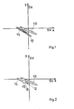
- FIG. 1 the area of the interference signals is designated 10 and the area of the error signals 12. It can be seen from areas 10 and 12 that there are both differences and overlaps between the complex interferer and measurement signals. In the case of small errors in particular, the corresponding complex measured values can fall entirely within the overlap area of the interference and error signals. This overlap area is designated by 14 in FIG. 1.
- the areas 10, 12 and 14 are also referred to below as features 10, 12 and 14.
- the complex measured values that arise during a test cycle depend on the frequency of the scanning used and on the test speed.
- a disturbance signal assigned to a specific interference effect passes through certain values within the range 10. Only if the corresponding signal with a predetermined number of complex measured values has passed through certain ranges 10, 12 and 14 can a clear assignment to a specific feature type be possible. However, the proper order of the transition between areas 10, 12 and 14 is important for a certain type of feature. If the order changes, then this is not a sign of a certain signal type but the sign of an error in the material.
- the various signal types are determined on the basis of numerous complex measured values. About ten to fifteen complex measured values are sufficient to determine an interfering signal. Depending on their sequence, these measured values are checked as to whether they lie within the limits of the areas determined for the respective test object, which are only traversed by interfering signals, interfering signals and error signals, or only error signals. At the same time, the complex measured values of the respective cycle are saved.
- Certain complex measured values are not intended for further processing. These are measured values that have a range zero Point 16 correspond or the area zero 16, which is shown in Fig. 2, are closely adjacent. The limit beyond which complex measured values are processed is given by a base threshold designated by 18. Measured values that lie within this basic threshold 18 cannot supply data that can be processed in a meaningful manner. If an interferer signal occurs during the measuring cycle, then the first complex measured values, starting from the basic threshold 19, lie in the area 10 assigned to the interferer signals, which is also traversed by the further complex measured values. The number of complex measured values that are allocated to area 10 depends on the clock rate with which the measured values are taken from the output signal of the coil, on the relative speed between the test object and the coil, and on the time at which the interference signals originated within the specified sampling cycle.
- the complex measured values can then traverse curves within area 14 before area 12 is reached after passing through the zero area. If the order in which the areas pass through changes, this is an indication that a special type of interfering signal is not present. While the complex measured values pass through areas 10, 14 and 12 with a pure interferer signal, complex measured values can only occur in areas 12 and 14 with an error signal without an interferer signal. If the fault signal and the fault signal occur at the same time, these range limits are exceeded and a decision is therefore made automatically on faults. After the position and the sequence of the complex measured values obtained during a scanning process with regard to the areas 10, 12 and 14 have been checked, it is determined whether only an interfering signal, an interfering signal in connection with an error signal or only an error signal has occurred.
- the complex measured values obtained and stored during a scanning process are processed in various ways. If there is only one interfering signal, the complex measured values can be deleted or registered as such. If an interference signal has been detected in connection with an error signal, interference suppression is carried out. The nature of the interfering signal can also be recognized from the course of the complex measured values. It is therefore possible to provide suppression measures adapted to the interference effects.
- the existing complex measured values are transformed according to the method typical for the type of fault, so that the new values only contain the error signal part. In many cases, however, the measuring accuracy is reduced.
- the error signals in which no interference signals have been found and the error signals freed from interference signals are then processed further.
- the type of error is determined on the basis of the typical course of the complex measured values within the areas 12 and 14.
- the complex measured values are preferably divided into the following error classes: hole, internal crack, external crack and indefinable errors. Indefinable errors are not processed further, but are reported to the operating personnel by specifying the UUT number.
- a further step follows in which the complex measured values obtained during a test cycle are processed. This step involves determining the depth of error.
- the depth of error is determined based on the type of error found and the size of the advertisement. The relationship between the size of the advertisement and the depth of error can be specified and can be used to determine the respective depth of error from a given advertisement size.
- an eddy current test device 20 is present, with which a test body (not shown), for example a pipe, is examined.
- the test device 20 outputs digital, complex measured values on a data bus 22, which correspond to the output signal of the sensor coil of the test device 20, not shown.
- the complex measured values are stored in a RAM 24 which works on the F.FO principle (first-in, first-out).
- the complex measured values present on the data bus 22 also form addresses for three further memories 26, 28, 30, which are preferably designed as ROM memories.
- the three memories 26, 28, 30 are assigned to areas 10, 12 and 14, respectively.
- a bit is stored in the memories 26, 28, 30 under the respective address, which indicates whether or not the complex measured value forming the address falls within the respective range. This enables a very quick assignment of the complex measured values to the areas.
- the basic threshold 18 specifies a measure of how many digits must be present in the memory 24 for the respective area per address. With a data format of the data bus 22 of twelve bits, the eight bits with the higher place values are sufficient to precisely differentiate the area values from one another. In many cases, the six bits with the higher positions are sufficient.
- the test device 20 is also connected to the counter input of a counter 32, which monitors the number of complex measured values per sampling cycle. Depending on the type of possible interference signals, the sampling rate and the test speed, the counter 32 is preset to a corresponding value.
- the total number of complex measured values can also be regarded as a type of code word, the length of which is determined by the preset value of the counter 32.
- the counter 32 is reduced in content by one for each new complex measured value. When the counting content is zero, the counter 32 outputs a signal to an input circuit 34 of a microcomputer 36.
- the outputs of the memories 26, 28, 30 are each connected to a memory stage of a first register 38.
- the outputs of the stages of the register 38 are connected to inputs of a comparator 40 and each to inputs of memory stages of a second register 42, the outputs of which are connected to the second inputs of the comparator 40.
- the comparator 40 compares the binary values present at its inputs for equality and for the condition greater or less than the value present at a particular input.
- the first register 38 is connected via OR logic elements 44 to a third register 46, the outputs of which are also connected to inputs of the OR logic elements 44. Furthermore, the outputs of the stages of the third register 46 are connected to the input circuit 34 via an AND gate 48.
- the data record in the memory 24 is released via the reset line 71 or can be registered via a bus 71.
- the outputs of the memory 24, on the other hand, are connected via a further data channel 50 to inputs of a second FIFO memory 52 and to inputs of three further memories 54, 56, 58, which can also be ROM memories, in the event of a negative interference decision.
- the output signals of the memory 24, which are the complex measured values, also serve as addresses for the memories 54, 56, 58, which establish a link between the complex measured values and for these typical types of error.
- the contents of the cells of the memory 54 indicate the values for holes in the test specimen associated with specific addresses.
- the memories 56 and 58 contain the features which are typical of internal cracks and external cracks.
- the outputs of the memories 54, 56, 58 are each connected to an additional input circuit 60 of the microcomputer 36.
- the outputs of the memory 52 are connected to a further memory 62, which is provided for determining the error size.
- the memory 52 is also connected to a display device, not shown.
- the outputs of the memory. 62 are connected to the microcomputer 36 via an input and output circuit 64.
- the input and output circuit 64 has outputs 66 for controlling marking and / or sorting devices for the test specimens.
- a screen terminal 68 and a large-capacity memory 70 can also be connected to the microcomputer 36.
- the registers 38, 42 and 46 consist, for example, of three memory levels (the number of memory levels depends on the number of areas required for signal description, which are each connected to the three memories 26, 28, 30, which are used for three areas 10, 12 and 14 are present).
- a complex measured value occurs at the output of the test device 20 during a measurement cycle, then this addresses the memories 26, 28 and 30.
- the memory in the area of which the complex measured value falls issues a message to the downstream memory stage of the register 38.
- Register 38 can only contain one message implemented by a binary value if the device is working properly.
- the result of the test of the previous complex measured value is stored in register 42, for example.
- the comparator 40 now determines whether the contents of the registers 38, 40 are the same or whether the contents of the register 38 are larger or smaller than the contents of the register 42. Assuming that the least significant digit is associated with the output of memory 26, the comparator output signal, which determines that the contents of register 42 is less than that of register 38, is an error signal.
- registers 38 and 46 are connected to one another in an OR operation by logic elements 44. The result is again stored in register 46. Because of this OR operation, all positions in register 46 are filled with the same binary values at the end of the measuring cycle if all areas 10, 12, 14 have been covered by the complex measured values. This is a criterion for the fact that an interference signal together with an error signal is contained in the course of the complex measured values.
- the microcomputer 36 releases the contents of the memory 24 for further processing, which consists in suppressing the interference signal with subsequent error classification via the memories 54, 56, 58. After the fault classification, the depth of the fault is determined on the basis of the complex measured values via the memory 62.
- the size of the memories 24 and 52 is to be adapted to the number of complex measured values that occur per measuring cycle. The statements made above in connection with the memory 24 also apply to the data width of the measured values in the memory 52.
- the number of memories connected to the input circuit 60 corresponds to the number of types of errors.
- the counter 32 shows the computer 36 the end of the measuring cycle.
- the microcomputer 36 then, by processing the output signal of the comparator 40, causes the measurement values contained in the memory 24 to be used for the error classification and the simultaneous storage in the memory 52.
- the information in the FIFO memory 24 is transmitted via the reset line 71 deleted or if storage of all interferer data is desired, made available for registration via a separate data bus 72.
- the microcomputer 36 then controls the determination of the error depth on the basis of the respectively classified errors.
- the arrangement shown in Fig. 3 enables the processing of a single complex measured value in about 10 usec.
- the processing time is thus considerably shorter than the measuring gate times of the individual measuring frequencies. In the case of a test device 20, which generates several frequencies in the 1kHz grid, this means that about 15 msec are required for fifteen measured values. If these measured values are processed in the specified system cycle, this time occurs in each of the method steps described above. The result of the processing is therefore available with a delay of about 50 msec. This time is so short that even in the event of an error detected at the end of the test specimen, sufficient time remains for the activation of a marking or sorting device.
Landscapes
- Chemical & Material Sciences (AREA)
- Chemical Kinetics & Catalysis (AREA)
- Electrochemistry (AREA)
- Physics & Mathematics (AREA)
- Health & Medical Sciences (AREA)
- Life Sciences & Earth Sciences (AREA)
- Analytical Chemistry (AREA)
- Biochemistry (AREA)
- General Health & Medical Sciences (AREA)
- General Physics & Mathematics (AREA)
- Immunology (AREA)
- Pathology (AREA)
- Investigating Or Analyzing Materials By The Use Of Magnetic Means (AREA)
Applications Claiming Priority (2)
| Application Number | Priority Date | Filing Date | Title |
|---|---|---|---|
| DE19823213267 DE3213267A1 (de) | 1982-04-08 | 1982-04-08 | Verfahren und vorrichtung zur pruefung von werkstoffen nach dem wirbelstromprinzip |
| DE3213267 | 1982-04-08 |
Publications (2)
| Publication Number | Publication Date |
|---|---|
| EP0092094A1 true EP0092094A1 (fr) | 1983-10-26 |
| EP0092094B1 EP0092094B1 (fr) | 1986-08-20 |
Family
ID=6160627
Family Applications (1)
| Application Number | Title | Priority Date | Filing Date |
|---|---|---|---|
| EP83103286A Expired EP0092094B1 (fr) | 1982-04-08 | 1983-04-05 | Procédé et dispositif pour tester des matériaux selon le principe des courants de Foucault |
Country Status (5)
| Country | Link |
|---|---|
| US (1) | US4628261A (fr) |
| EP (1) | EP0092094B1 (fr) |
| JP (1) | JPS58186043A (fr) |
| CA (1) | CA1195733A (fr) |
| DE (1) | DE3213267A1 (fr) |
Cited By (5)
| Publication number | Priority date | Publication date | Assignee | Title |
|---|---|---|---|---|
| EP0117786A1 (fr) * | 1983-02-24 | 1984-09-05 | AEROSPATIALE Société Nationale Industrielle | Procédé et dispositif pour l'examen non destructif de jonctions rivetées ou analogues au moyen d'une sonde à courants de Foucault |
| GB2187558A (en) * | 1986-03-04 | 1987-09-09 | Atomic Energy Authority Uk | Determining the magnetic flux density within a specimen during magnetic particle inspection techniques |
| GB2188156A (en) * | 1986-03-17 | 1987-09-23 | Atomic Energy Authority Uk | Magnetic discontinuity detection |
| EP0257603A3 (fr) * | 1986-08-27 | 1989-05-31 | Törnbloms Kvalitetskontroll Ab | Procédé d'essai à courants de Foucault d'objets non-magnétiques |
| FR2689637A1 (fr) * | 1992-04-06 | 1993-10-08 | Aerospatiale | Procédé et installation de contrôle non destructif d'une pièce utilisant un capteur à courants de foucault. |
Families Citing this family (21)
| Publication number | Priority date | Publication date | Assignee | Title |
|---|---|---|---|---|
| JPS6193949A (ja) * | 1984-10-15 | 1986-05-12 | Hitachi Ltd | 渦電流検査装置 |
| US4878180A (en) * | 1985-11-18 | 1989-10-31 | Western Atlas International, Inc. | Method of evaluating the condition of tubular goods |
| DE3542159A1 (de) * | 1985-11-28 | 1987-06-04 | Nukem Gmbh | Verfahren zur werkstoffpruefung nach dem wirbelstromprinzip und vorrichtung zur durchfuehrung des verfahrens |
| US4823082A (en) * | 1986-02-18 | 1989-04-18 | Kabushiki Kaisha Kobe Seiko Sho | Signal processing method for an electromagnetic induction test |
| SE456611B (sv) * | 1986-04-18 | 1988-10-17 | Tornbloms Kvalitetskontroll Ab | Anordning for signallagring och/eller signalbehandling av fran en givare erhallna signaler |
| US4763274A (en) * | 1986-06-24 | 1988-08-09 | Westinghouse Electric Corp. | Machine implemented analysis eddy current data |
| DE3720686A1 (de) * | 1987-06-23 | 1989-01-05 | Foerster Inst Dr Friedrich | Verfahren zum untersuchen eines objektes |
| JPH0254165A (ja) * | 1988-08-19 | 1990-02-23 | Kobe Steel Ltd | 管棒材の渦流探傷方法 |
| US5004724A (en) * | 1989-03-09 | 1991-04-02 | International Superconductor Corp. | Superconductive quantum interference device for the non-destructive evaluation of metals |
| US5068800A (en) * | 1989-03-14 | 1991-11-26 | Rem Technologies, Inc. | Crack detection method for shaft at rest |
| US4975855A (en) * | 1989-03-14 | 1990-12-04 | Rem Technologies, Inc. | Shaft crack detection method |
| US5159563A (en) * | 1989-03-14 | 1992-10-27 | Rem Technologies, Inc. | Crack detection method for operating shaft |
| US5144565A (en) * | 1990-03-26 | 1992-09-01 | K. J. Law Engineers, Inc. | Measurement of metallurgical properties in ferromagnetic test parts |
| US5345514A (en) * | 1991-09-16 | 1994-09-06 | General Electric Company | Method for inspecting components having complex geometric shapes |
| US5602474A (en) * | 1995-06-06 | 1997-02-11 | United Technologies Corporation | Detecting cracks in non-uniform areas of metal parts including position correlation |
| EP1430297B1 (fr) * | 2001-09-24 | 2006-06-14 | ALSTOM Technology Ltd | Procede et dispositif de controle d'empilements de toles de fer feuilletees de machines electriques a la recherche de courts-circuits entre toles |
| US6815957B2 (en) | 2001-09-24 | 2004-11-09 | Alstom (Switzerland) Ltd | Method and device for inspecting laminated iron cores of electrical machines for interlamination shorts |
| US6563309B2 (en) * | 2001-09-28 | 2003-05-13 | The Boeing Company | Use of eddy current to non-destructively measure crack depth |
| US7436992B2 (en) * | 2004-07-30 | 2008-10-14 | General Electric Company | Methods and apparatus for testing a component |
| US8013599B2 (en) * | 2004-11-19 | 2011-09-06 | General Electric Company | Methods and apparatus for testing a component |
| CN114088807A (zh) * | 2020-08-05 | 2022-02-25 | 常州常宝精特钢管有限公司 | 冷轧钢管涡流检验不相关信号的分析方法 |
Citations (8)
| Publication number | Priority date | Publication date | Assignee | Title |
|---|---|---|---|---|
| US3302105A (en) * | 1964-08-26 | 1967-01-31 | Hugo L Libby | Eddy current nondestructive testing device using an oscilloscope to identify and locate irregularities in a test piece |
| US3895290A (en) * | 1972-08-03 | 1975-07-15 | Commissariat Energie Atomique | Defect detection system using an AND gate to distinguish specific flaw parameters |
| US3904957A (en) * | 1973-09-29 | 1975-09-09 | Foerster Inst Dr Friedrich | Eddy current test apparatus with peak signal value storage means |
| US4061968A (en) * | 1976-09-07 | 1977-12-06 | Commissariat A L'energie Atomique | Process of and apparatus for non-destructive eddy current testing involves the suppression of displayed lobes corresponding to fault parameters to be eliminated from the display |
| GB2010492A (en) * | 1977-12-15 | 1979-06-27 | Babcock & Wilcox Co | Method for the detection of flaws in a tube proximate a contiguous member |
| DE2937865A1 (de) * | 1979-09-19 | 1981-04-02 | Kraftwerk Union AG, 4330 Mülheim | Verfahren zur automatischen auswertung der signale von wirbelstrommesssonden |
| DE3029936A1 (de) * | 1980-08-07 | 1982-03-04 | Kraftwerk Union AG, 4330 Mülheim | Verfahren zur einstellung von wirbelstrompruefgeraeten |
| EP0068503A2 (fr) * | 1981-06-30 | 1983-01-05 | Nukem GmbH | Méthode et dispositif d'essai de matériaux par le principe des courants de foucault |
Family Cites Families (15)
| Publication number | Priority date | Publication date | Assignee | Title |
|---|---|---|---|---|
| DE68503C (de) * | S. HlRSCHFELD'ER in München und L. DÄNNhauser in New-York | Photographischer Apparat mit schwingender Objectivhülse für ebene Platten | ||
| GB1551954A (en) * | 1975-05-28 | 1979-09-05 | Hoffmann La Roche | Standardization of a physiochemical parameter of a batch of formulation in tabletted form |
| US4059795A (en) * | 1976-06-03 | 1977-11-22 | Sensor Corporation | Digital eddy current apparatus for sensing and analyzing metallurgical characteristics of an electrically conductive material |
| US4207520A (en) * | 1978-04-06 | 1980-06-10 | The United States Of America As Represented By The Secretary Of The Air Force | Multiple frequency digital eddy current inspection system |
| FR2422952A1 (fr) * | 1978-04-10 | 1979-11-09 | Siderurgie Fse Inst Rech | Procede et dispositif de detection par courants de foucault des variations d'un parametre lie a un produit metallique |
| US4210904A (en) * | 1978-09-12 | 1980-07-01 | Krautkramer-Branson, Incorporated | Method and apparatus for converting analog ultrasonic echo signals into digital form |
| US4230987A (en) * | 1979-02-26 | 1980-10-28 | Sensor Corporation | Digital eddy current apparatus for generating metallurgical signatures and monitoring metallurgical contents of an electrically conductive material |
| FR2451032A1 (fr) * | 1979-03-09 | 1980-10-03 | Commissariat Energie Atomique | Appareil numerique pour le controle de pieces par courants de foucault |
| US4349880A (en) * | 1979-03-19 | 1982-09-14 | Rca Corporation | Inspection system for detecting defects in regular patterns |
| JPS5677704A (en) * | 1979-11-30 | 1981-06-26 | Hitachi Ltd | Inspection system for surface defect of substance |
| DE3024716C2 (de) * | 1980-06-30 | 1986-10-23 | Dr. Johannes Heidenhain Gmbh, 8225 Traunreut | Digitales Längen- oder Winkelmeßsystem |
| US4450405A (en) * | 1980-07-14 | 1984-05-22 | The Boeing Company | Alloy testing apparatus using eddy current conductivity probe |
| US4437164A (en) * | 1981-03-05 | 1984-03-13 | Bristol Babcock Inc. | Ridge circuit compensation for environmental effects |
| US4455529A (en) * | 1981-06-08 | 1984-06-19 | Schlumberger Technology Corporation | Digital induction logging tool including means for measuring phase quadrature components in a phase sensitive detector |
| US4485451A (en) * | 1982-01-28 | 1984-11-27 | Obedineni Zavodi Za Zapametyavashti Ustroystva | System for monitoring dynamic parameters of magnetic heads |
-
1982
- 1982-04-08 DE DE19823213267 patent/DE3213267A1/de not_active Withdrawn
-
1983
- 1983-04-05 EP EP83103286A patent/EP0092094B1/fr not_active Expired
- 1983-04-05 US US06/482,284 patent/US4628261A/en not_active Expired - Fee Related
- 1983-04-06 CA CA000425366A patent/CA1195733A/fr not_active Expired
- 1983-04-08 JP JP58061078A patent/JPS58186043A/ja active Pending
Patent Citations (8)
| Publication number | Priority date | Publication date | Assignee | Title |
|---|---|---|---|---|
| US3302105A (en) * | 1964-08-26 | 1967-01-31 | Hugo L Libby | Eddy current nondestructive testing device using an oscilloscope to identify and locate irregularities in a test piece |
| US3895290A (en) * | 1972-08-03 | 1975-07-15 | Commissariat Energie Atomique | Defect detection system using an AND gate to distinguish specific flaw parameters |
| US3904957A (en) * | 1973-09-29 | 1975-09-09 | Foerster Inst Dr Friedrich | Eddy current test apparatus with peak signal value storage means |
| US4061968A (en) * | 1976-09-07 | 1977-12-06 | Commissariat A L'energie Atomique | Process of and apparatus for non-destructive eddy current testing involves the suppression of displayed lobes corresponding to fault parameters to be eliminated from the display |
| GB2010492A (en) * | 1977-12-15 | 1979-06-27 | Babcock & Wilcox Co | Method for the detection of flaws in a tube proximate a contiguous member |
| DE2937865A1 (de) * | 1979-09-19 | 1981-04-02 | Kraftwerk Union AG, 4330 Mülheim | Verfahren zur automatischen auswertung der signale von wirbelstrommesssonden |
| DE3029936A1 (de) * | 1980-08-07 | 1982-03-04 | Kraftwerk Union AG, 4330 Mülheim | Verfahren zur einstellung von wirbelstrompruefgeraeten |
| EP0068503A2 (fr) * | 1981-06-30 | 1983-01-05 | Nukem GmbH | Méthode et dispositif d'essai de matériaux par le principe des courants de foucault |
Non-Patent Citations (1)
| Title |
|---|
| MATERIALS EVALUATION, Januar 1975, V.S. CECCO et al. "Eddy current in-situ inspection of ferromagnetic monel tubes", Seiten 1-4 * |
Cited By (8)
| Publication number | Priority date | Publication date | Assignee | Title |
|---|---|---|---|---|
| EP0117786A1 (fr) * | 1983-02-24 | 1984-09-05 | AEROSPATIALE Société Nationale Industrielle | Procédé et dispositif pour l'examen non destructif de jonctions rivetées ou analogues au moyen d'une sonde à courants de Foucault |
| GB2187558A (en) * | 1986-03-04 | 1987-09-09 | Atomic Energy Authority Uk | Determining the magnetic flux density within a specimen during magnetic particle inspection techniques |
| GB2187558B (en) * | 1986-03-04 | 1990-07-04 | Atomic Energy Authority Uk | A method and apparatus for determining the magnetic flux density within a specimen in magnetic particle inspection techniques |
| GB2188156A (en) * | 1986-03-17 | 1987-09-23 | Atomic Energy Authority Uk | Magnetic discontinuity detection |
| US4814705A (en) * | 1986-03-17 | 1989-03-21 | The Secretary Of State For United Kingdom Atomic Energy Authority In Her Britannic Majesty's Government Of The United Kingdom Of Great Britain And Northern Ireland | Method and apparatus for magnetic discontinuity detection in a specimen of magnetizable material |
| GB2188156B (en) * | 1986-03-17 | 1990-06-13 | Atomic Energy Authority Uk | Magnetic discontinuity detection |
| EP0257603A3 (fr) * | 1986-08-27 | 1989-05-31 | Törnbloms Kvalitetskontroll Ab | Procédé d'essai à courants de Foucault d'objets non-magnétiques |
| FR2689637A1 (fr) * | 1992-04-06 | 1993-10-08 | Aerospatiale | Procédé et installation de contrôle non destructif d'une pièce utilisant un capteur à courants de foucault. |
Also Published As
| Publication number | Publication date |
|---|---|
| EP0092094B1 (fr) | 1986-08-20 |
| DE3213267A1 (de) | 1983-10-20 |
| US4628261A (en) | 1986-12-09 |
| JPS58186043A (ja) | 1983-10-29 |
| CA1195733A (fr) | 1985-10-22 |
Similar Documents
| Publication | Publication Date | Title |
|---|---|---|
| EP0092094B1 (fr) | Procédé et dispositif pour tester des matériaux selon le principe des courants de Foucault | |
| EP0095517B1 (fr) | Procédure et dispositif pour une suspection optique automatique | |
| DE3885119T2 (de) | Verfahren und Einrichtung zur Inspektion von bewegten Werkstücken entlang einer Produktionslinie. | |
| DE2612613C3 (de) | Verfahren und Schaltungsanordnung zum Identifizieren von Gegenständen, insbesondere von Münzen oder Wertpapieren | |
| DE3013833C2 (de) | Vorrichtung zur Prüfung eines auf einem Gegenstand befindlichen Musters auf Fehler | |
| EP2204660B1 (fr) | Dispositif et procédé de détermination de déchargements partiels sur un composant électrique | |
| DE3336471A1 (de) | Verfahren und anordnung zur inspektion von bildern | |
| WO1991006392A1 (fr) | Procede et dispositif pour la determination automatique de parametres pour des systemes de controle de processus a comportement au transfert inconnu, notamment pour systemes de controle de processus destines au soudage par points | |
| DE3542159A1 (de) | Verfahren zur werkstoffpruefung nach dem wirbelstromprinzip und vorrichtung zur durchfuehrung des verfahrens | |
| EP0039793A2 (fr) | Procédé et appareil pour interpréter un signal de défaut | |
| DE19950331A1 (de) | Verfahren und Vorrichtung zum Prüfen einer Schneidengeometrie eines drehantreibbaren Werkzeugs | |
| EP0068503B1 (fr) | Méthode et dispositif d'essai de matériaux par le principe des courants de foucault | |
| DE1902318A1 (de) | Verfahren zur Herstellung von Erzeugnissen in groesseren Mengen unter Zuhilfenahme eines Rechners | |
| DE2338628A1 (de) | Anordnung zum steuern einer alarmausloesung | |
| DE69019960T2 (de) | Vorrichtung und verfahren zur selbsttätigen rechnung der güte einer elektrischen wicklung. | |
| DE19961817A1 (de) | Frequenzabweichung detektierendes Gerät und Frequenzabweichungs-Detektionsverfahren | |
| DE3113440A1 (de) | "verfahren zur ueberpruefung von gleichartigen objekten auf fehler" | |
| EP0106181A2 (fr) | Procédé d'essai pour déterminer l'exactitude de machines à outil et dispositif pour la mise en oeuvre | |
| DE3490374T1 (de) | Gut/Schlecht-Unterscheidungsgerät für Meßdaten | |
| DE3516214A1 (de) | Geraet zum pruefen der haerte von eisenteilen | |
| DE3120522C2 (de) | Verfahren zur Bestimmung von Werkstoffeigenschaften | |
| DE2544929C3 (de) | Verfahren zum Ermitteln von sporadischen Fehlern in Fernmelde-, insbesondere Fernsprechanlagen | |
| DE1939464A1 (de) | Verfahren zum gleichzeitigen Ermitteln der emittierten Strahlung oder Partikel von mehreren verschiedenen radioaktiven Proben sowie eine Vorrichtung zur Duchfuehrung des Verfahrens | |
| DE3527972A1 (de) | Wirbelstrom-pruefverfahren fuer staebe, draehte oder rohre | |
| DE3714298C2 (de) | Verfahren zum Einstellen einer Münzunterscheidungseinrichtung |
Legal Events
| Date | Code | Title | Description |
|---|---|---|---|
| PUAI | Public reference made under article 153(3) epc to a published international application that has entered the european phase |
Free format text: ORIGINAL CODE: 0009012 |
|
| AK | Designated contracting states |
Designated state(s): FR IT SE |
|
| 17P | Request for examination filed |
Effective date: 19840202 |
|
| GRAA | (expected) grant |
Free format text: ORIGINAL CODE: 0009210 |
|
| AK | Designated contracting states |
Kind code of ref document: B1 Designated state(s): FR IT SE |
|
| ITF | It: translation for a ep patent filed | ||
| ET | Fr: translation filed | ||
| PLBI | Opposition filed |
Free format text: ORIGINAL CODE: 0009260 |
|
| 26 | Opposition filed |
Opponent name: ASEA AKTIEBOLAG Effective date: 19870516 |
|
| RDAG | Patent revoked |
Free format text: ORIGINAL CODE: 0009271 |
|
| STAA | Information on the status of an ep patent application or granted ep patent |
Free format text: STATUS: PATENT REVOKED |
|
| 27W | Patent revoked |
Effective date: 19871015 |
|
| EUG | Se: european patent has lapsed |
Ref document number: 83103286.7 Effective date: 19890726 |