EP0068604A2 - Transduktoren - Google Patents
Transduktoren Download PDFInfo
- Publication number
- EP0068604A2 EP0068604A2 EP82302089A EP82302089A EP0068604A2 EP 0068604 A2 EP0068604 A2 EP 0068604A2 EP 82302089 A EP82302089 A EP 82302089A EP 82302089 A EP82302089 A EP 82302089A EP 0068604 A2 EP0068604 A2 EP 0068604A2
- Authority
- EP
- European Patent Office
- Prior art keywords
- transducer
- store
- module
- calibration data
- digital
- Prior art date
- Legal status (The legal status is an assumption and is not a legal conclusion. Google has not performed a legal analysis and makes no representation as to the accuracy of the status listed.)
- Withdrawn
Links
Images


Classifications
-
- G—PHYSICS
- G01—MEASURING; TESTING
- G01D—MEASURING NOT SPECIALLY ADAPTED FOR A SPECIFIC VARIABLE; ARRANGEMENTS FOR MEASURING TWO OR MORE VARIABLES NOT COVERED IN A SINGLE OTHER SUBCLASS; TARIFF METERING APPARATUS; MEASURING OR TESTING NOT OTHERWISE PROVIDED FOR
- G01D5/00—Mechanical means for transferring the output of a sensing member; Means for converting the output of a sensing member to another variable where the form or nature of the sensing member does not constrain the means for converting; Transducers not specially adapted for a specific variable
- G01D5/12—Mechanical means for transferring the output of a sensing member; Means for converting the output of a sensing member to another variable where the form or nature of the sensing member does not constrain the means for converting; Transducers not specially adapted for a specific variable using electric or magnetic means
- G01D5/14—Mechanical means for transferring the output of a sensing member; Means for converting the output of a sensing member to another variable where the form or nature of the sensing member does not constrain the means for converting; Transducers not specially adapted for a specific variable using electric or magnetic means influencing the magnitude of a current or voltage
- G01D5/24—Mechanical means for transferring the output of a sensing member; Means for converting the output of a sensing member to another variable where the form or nature of the sensing member does not constrain the means for converting; Transducers not specially adapted for a specific variable using electric or magnetic means influencing the magnitude of a current or voltage by varying capacitance
- G01D5/241—Mechanical means for transferring the output of a sensing member; Means for converting the output of a sensing member to another variable where the form or nature of the sensing member does not constrain the means for converting; Transducers not specially adapted for a specific variable using electric or magnetic means influencing the magnitude of a current or voltage by varying capacitance by relative movement of capacitor electrodes
- G01D5/2412—Mechanical means for transferring the output of a sensing member; Means for converting the output of a sensing member to another variable where the form or nature of the sensing member does not constrain the means for converting; Transducers not specially adapted for a specific variable using electric or magnetic means influencing the magnitude of a current or voltage by varying capacitance by relative movement of capacitor electrodes by varying overlap
-
- G—PHYSICS
- G01—MEASURING; TESTING
- G01D—MEASURING NOT SPECIALLY ADAPTED FOR A SPECIFIC VARIABLE; ARRANGEMENTS FOR MEASURING TWO OR MORE VARIABLES NOT COVERED IN A SINGLE OTHER SUBCLASS; TARIFF METERING APPARATUS; MEASURING OR TESTING NOT OTHERWISE PROVIDED FOR
- G01D3/00—Indicating or recording apparatus with provision for the special purposes referred to in the subgroups
- G01D3/02—Indicating or recording apparatus with provision for the special purposes referred to in the subgroups with provision for altering or correcting the law of variation
- G01D3/022—Indicating or recording apparatus with provision for the special purposes referred to in the subgroups with provision for altering or correcting the law of variation having an ideal characteristic, map or correction data stored in a digital memory
Definitions
- This invention relates to a method of incorporating a calibration into a transducer package.
- the following description relates particularly to capacitative transducers.
- the method may apply to any transducer system which has a sufficiently stable characteristic.
- Linear capacitative displacement transducers can be manufactured which will give a continuously variable capacitance with respect to displacement.
- the relation between the two In order to use the variation in capacity as a measure of displacement the relation between the two must be known with sufficient precision to give an output signal of the required accuracy.
- the transducer may cost too much to produce.
- the stability of the relationship between capacity change and linear displacement may be as high as a few parts per million.
- the peak to peak differences in the calibration curves may be as much as a few thousand parts per million. Hitherto it has been attempted to standardise the manufacturing process so as to produce transducers having identical characteristics. But I now believe that it may be more expedient to accept variations in behaviour within a range of acceptable properties and to build in a calibration correction. If now an appropriate correction is built into each transducer, then the departure of the output signal of each from an ideal "straight line" or linear law may be reduced by any desired degree.
- the invention provides a transducer assembly comprising in combination:
- the invention provides a transducer assembly comprising a transducer member, a store associated with the transducer member in which calibration data for that transducer is recorded in digital form, which data may be used to modify the apparent output to give a true output corresponding to the intended transducer law, and electrical connections to the transducer arranged so that whenever the transducer member is connected to a processor module the associated store is also connected thereto.
- a calibration curve in the form of a polynomial expression may be built into the transducer.
- This polynomial represents the calibration curve of a particular transducer and is unique to that transducer.
- the transducer designer and manufacturer can now concentrate on stability and reproducibility while a built in calibration device defines the law which connects the input variable with the output variable of the transducer to whatever degree of accuracy is needed and is justified by the stability of the transducer.
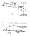
- a multi-way plug and socket are used ( Figure 1).
- the pins of the plug 10 are connected in a binary pattern which represents the calibration.
- a 25 way plug is used and that 5 leads of this plug are used as connections to the transducer 12 via analog to digital converter 13. This leaves 20 pins free.
- the presence of this fixed calibration factor on the said multiway electrical connector may be used to modify the response of the device, ie. to convert the measured value of a variable into a true value which may be used for direct measurement.
- a digital processor 14 will multiply the apparent setting y of the transducer by the polynomial recorded on the plug. If for example in the equation mentioned a, b, c, d are defined by 5 binary digits each, then each element can have + 0 to 16 as a multiplier. In practice the type of error found in some transducers may require only that b and c are assigned values and also that b should have say 12 bit resolution. In other situations an even higher order polynomial might be envisaged.
- the digital data can be stored on some other digital storage medium.
- One such storage device is a "Programmable Read Only Memory” or PROM. This device may have the calibration characteristics of a particlar transducer recorded on it in digital form. The transducer is connected to a device which converts the transducer setting into a usable signal.
- the device recognises the transducer output, digitises the output, uses the digital setting to operate a correcting device such as a digital adder or multiplier, derives the factor for correction from the PROM store by addressing the PROM in the usual manner, and interprets the data stored in that address in such a way as to allow the transducer apparent setting to be modified to a true setting.
- a correcting device such as a digital adder or multiplier
- a further extension of this principle can apply to a transducer which is constructed so that as the range of operation is traversed, a number of segmented active areas are interconnected in a manner that will extend the range and stability of the transducer.
- a linear capacitative displacement transducer is formed by a long row of discrete flat plates 20 arranged end to end.
- a single plate 22 moving along the line of the said series of plates has capacitative coupling to several of these plates.
- the row of plates is connected so that they form only two electrodes at any one time. As the moving plate 22 traverses along the line of plates 20 1 to 20 10 at potentials A 1 - A 10 it will have a capacitance to these plates.
- plates 22, 20 n and 20 (n+1) will form a differential capacitor and the voltage at 22 will vary according to how much plate 22 overlaps plate 20 n at potential C and plate 20 (n+1) at potential D.
- the switches S 1 to S 10 allow electrodes to be connected in groups. For example if S 5 is open and all the remaining switches S 1 to S 10 are closed, then the electrodes will be in two groups A l to A 5 and A 6 to A 10 . As electrode B moves along the line of these electrodes its potential will vary as long as it straddles the potential gap between plate 20 5 and plate 20 6 . As the edge of plate 22 approaches this gap, the switch S 5 can be closed, and S 6 opened. The potential gap has now been shifted along to between plate 206 and plate 20 7 and the linear range of the transducer operation extended, the output signal being shown in Figure 4.
- Such a transducer does not have to have flat plates and plates of cylindrical form (Figure 3c) may also be used.
- This scheme is particularly although not exclusively applicable to angular displacement transducer (Figure 4).
- an annular ring may be segmented into a series of arcuate electrodes.
- the pick-off electrode rotates the electrical gap is rotated so as to be located always under the pick off.
- a new exact position is registered in the digital store. Positions between are interpolated, and the resulting output will present a continuous and exact signal representing the angular setting of one set of electrodes with respect to the other.
- the underlying principle of this invention is that a unique digital representation of the transducer calibration which goes with the transducer is used to modify the apparent output to give a true output which conforms to a desired law.
Landscapes
- Engineering & Computer Science (AREA)
- Physics & Mathematics (AREA)
- General Physics & Mathematics (AREA)
- Power Engineering (AREA)
- Technology Law (AREA)
- Transmission And Conversion Of Sensor Element Output (AREA)
- Indication And Recording Devices For Special Purposes And Tariff Metering Devices (AREA)
Applications Claiming Priority (2)
| Application Number | Priority Date | Filing Date | Title |
|---|---|---|---|
| GB8112721A GB2097536A (en) | 1981-04-24 | 1981-04-24 | Correcting transducer measurements |
| GB8112721 | 1981-04-24 |
Publications (2)
| Publication Number | Publication Date |
|---|---|
| EP0068604A2 true EP0068604A2 (de) | 1983-01-05 |
| EP0068604A3 EP0068604A3 (de) | 1985-04-17 |
Family
ID=10521340
Family Applications (1)
| Application Number | Title | Priority Date | Filing Date |
|---|---|---|---|
| EP82302089A Withdrawn EP0068604A3 (de) | 1981-04-24 | 1982-04-23 | Transduktoren |
Country Status (2)
| Country | Link |
|---|---|
| EP (1) | EP0068604A3 (de) |
| GB (1) | GB2097536A (de) |
Cited By (1)
| Publication number | Priority date | Publication date | Assignee | Title |
|---|---|---|---|---|
| WO2001018496A3 (en) * | 1999-09-03 | 2002-09-12 | Microbridge Technologies Inc | Several gas flow measuring devices and signal processing methods |
Families Citing this family (13)
| Publication number | Priority date | Publication date | Assignee | Title |
|---|---|---|---|---|
| DE3242967A1 (de) * | 1982-11-20 | 1984-05-24 | Hans-Jörg Dipl.-Kfm. 4400 Münster Hübner | Verfahren und messgeraet zum messen und verarbeiten von kenngroessen der umgebungsatmosphaere, insbesondere unter tage |
| DE3243540A1 (de) * | 1982-11-25 | 1984-05-30 | Hans-Jörg Dipl.-Kfm. 4400 Münster Hübner | Verfahren und messgeraet zum messen und verarbeiten von kenngroessen der umgebungsatmosphaere, insbesondere unter tage |
| US4611304A (en) * | 1983-07-27 | 1986-09-09 | Sundstrand Data Control, Inc. | Transducer memory circuit |
| GB2183342A (en) * | 1985-10-24 | 1987-06-03 | Johnson Matthey Plc | Displaying corrected transducer readings |
| DE3736643A1 (de) * | 1987-10-29 | 1989-05-11 | Koenig Werner | Barometrische hoehenmessung unter beruecksichtigung der lufttemperatur |
| CH677144A5 (de) * | 1988-12-21 | 1991-04-15 | Weber Hans R | |
| AT403850B (de) * | 1990-08-10 | 1998-05-25 | Mecanotronic Produktion Von El | Verfahren zur kalibrierung |
| FR2682760A1 (fr) * | 1991-10-22 | 1993-04-23 | Prototype Mecanique Ind | Capteurs de deplacements lineaires ou angulaires sans contact. |
| GB9127112D0 (en) * | 1991-12-20 | 1992-02-19 | Schlumberger Ind Ltd | Smart displacement sensor |
| WO1996009528A1 (en) * | 1994-09-22 | 1996-03-28 | Southwest Research Institute | Sampling and measuring device with calibrating piston |
| DE19722744A1 (de) * | 1997-05-30 | 1998-12-03 | Draegerwerk Ag | Detektionssystem mit austauschbaren Sensoren |
| JP6438441B2 (ja) * | 2016-08-04 | 2018-12-12 | ファナック株式会社 | エンコーダの信号処理装置、エンコーダ、信号処理方法及びプログラム |
| CN107727029B (zh) * | 2017-09-21 | 2019-09-03 | 北京航空航天大学 | 一种磁轴承用位移传感器标定和检测装置 |
Family Cites Families (1)
| Publication number | Priority date | Publication date | Assignee | Title |
|---|---|---|---|---|
| FR2234550A1 (en) * | 1973-06-25 | 1975-01-17 | Integrated Photomatrix Ltd | Linearisation circuit for digital signals - with addition and multiplication factor logic units to generate output as an algebraic sum |
-
1981
- 1981-04-24 GB GB8112721A patent/GB2097536A/en not_active Withdrawn
-
1982
- 1982-04-23 EP EP82302089A patent/EP0068604A3/de not_active Withdrawn
Cited By (1)
| Publication number | Priority date | Publication date | Assignee | Title |
|---|---|---|---|---|
| WO2001018496A3 (en) * | 1999-09-03 | 2002-09-12 | Microbridge Technologies Inc | Several gas flow measuring devices and signal processing methods |
Also Published As
| Publication number | Publication date |
|---|---|
| GB2097536A (en) | 1982-11-03 |
| EP0068604A3 (de) | 1985-04-17 |
Similar Documents
| Publication | Publication Date | Title |
|---|---|---|
| EP0068604A2 (de) | Transduktoren | |
| EP0023732B1 (de) | Kapazitive Sonde | |
| EP0649010B1 (de) | Druckdifferenzmessverfahren und Verschiebungs-Umwandlungsvorrichtung | |
| US4543526A (en) | Capacitive device for the measurement of displacements | |
| CA1168887A (en) | Pressure transducer | |
| US4811491A (en) | Two-axis differential capacitance inclinometer | |
| JP2936286B2 (ja) | 精密容量性トランスデューサ回路と方法 | |
| AU603952B2 (en) | Capacitive position-sensing system | |
| US2867783A (en) | Measuring device | |
| US4102202A (en) | Electrostatic accelerometer | |
| US4449179A (en) | Means for capacitive measurement of displacements | |
| US4641434A (en) | Inclination measuring device | |
| JPH07260414A (ja) | 角度センサ | |
| JPS58211617A (ja) | 圧力トランスデユ−サ | |
| DE3711062A1 (de) | Kapazitive absolute positionsmessvorrichtung | |
| GB2043260A (en) | Liquid level measuring system | |
| US6940278B2 (en) | Angle transducer | |
| GB2097941A (en) | A circuit arrangement for measuring changes in inductance | |
| JPS62261070A (ja) | 測定装置 | |
| US3348133A (en) | Position responsive apparatus including a capacitive potentiometer | |
| US4082990A (en) | Electrostatic pickoff and torquer | |
| CN85100991B (zh) | 电容式位置传感器 | |
| CN119404080A (zh) | 用于确定界面的位置的传感器、液位计 | |
| SU1796880A1 (ru) | Emkocthый диффepehциaльhый пpeoбpaзobateль пepemeщehий | |
| RU2289789C1 (ru) | Устройство измерения перемещения подвижной массы микромеханического гироскопа по оси первичных колебаний |
Legal Events
| Date | Code | Title | Description |
|---|---|---|---|
| PUAI | Public reference made under article 153(3) epc to a published international application that has entered the european phase |
Free format text: ORIGINAL CODE: 0009012 |
|
| AK | Designated contracting states |
Designated state(s): DE FR |
|
| PUAL | Search report despatched |
Free format text: ORIGINAL CODE: 0009013 |
|
| AK | Designated contracting states |
Designated state(s): DE FR |
|
| STAA | Information on the status of an ep patent application or granted ep patent |
Free format text: STATUS: THE APPLICATION IS DEEMED TO BE WITHDRAWN |
|
| 18D | Application deemed to be withdrawn |
Effective date: 19851101 |