EP0068665A1 - Câble électrique blindé - Google Patents
Câble électrique blindé Download PDFInfo
- Publication number
- EP0068665A1 EP0068665A1 EP82302911A EP82302911A EP0068665A1 EP 0068665 A1 EP0068665 A1 EP 0068665A1 EP 82302911 A EP82302911 A EP 82302911A EP 82302911 A EP82302911 A EP 82302911A EP 0068665 A1 EP0068665 A1 EP 0068665A1
- Authority
- EP
- European Patent Office
- Prior art keywords
- insulating material
- conductor
- signal
- layer
- web
- Prior art date
- Legal status (The legal status is an assumption and is not a legal conclusion. Google has not performed a legal analysis and makes no representation as to the accuracy of the status listed.)
- Granted
Links
- 239000004020 conductor Substances 0.000 claims abstract description 61
- 239000011810 insulating material Substances 0.000 claims abstract description 29
- 239000002131 composite material Substances 0.000 claims description 4
- 239000000463 material Substances 0.000 description 3
- 238000000034 method Methods 0.000 description 3
- 229920003023 plastic Polymers 0.000 description 3
- 239000004033 plastic Substances 0.000 description 3
- 239000005030 aluminium foil Substances 0.000 description 1
- 238000007796 conventional method Methods 0.000 description 1
- 239000003989 dielectric material Substances 0.000 description 1
- 238000001125 extrusion Methods 0.000 description 1
- 239000011888 foil Substances 0.000 description 1
- 238000009413 insulation Methods 0.000 description 1
- 239000002184 metal Substances 0.000 description 1
- 229910052751 metal Inorganic materials 0.000 description 1
- 238000002360 preparation method Methods 0.000 description 1
Images
Classifications
-
- H—ELECTRICITY
- H01—ELECTRIC ELEMENTS
- H01B—CABLES; CONDUCTORS; INSULATORS; SELECTION OF MATERIALS FOR THEIR CONDUCTIVE, INSULATING OR DIELECTRIC PROPERTIES
- H01B11/00—Communication cables or conductors
- H01B11/18—Coaxial cables; Analogous cables having more than one inner conductor within a common outer conductor
- H01B11/20—Cables having a multiplicity of coaxial lines
- H01B11/203—Cables having a multiplicity of coaxial lines forming a flat arrangement
-
- H—ELECTRICITY
- H01—ELECTRIC ELEMENTS
- H01B—CABLES; CONDUCTORS; INSULATORS; SELECTION OF MATERIALS FOR THEIR CONDUCTIVE, INSULATING OR DIELECTRIC PROPERTIES
- H01B11/00—Communication cables or conductors
- H01B11/02—Cables with twisted pairs or quads
- H01B11/06—Cables with twisted pairs or quads with means for reducing effects of electromagnetic or electrostatic disturbances, e.g. screens
- H01B11/10—Screens specially adapted for reducing interference from external sources
- H01B11/1016—Screens specially adapted for reducing interference from external sources composed of a longitudinal lapped tape-conductor
-
- H—ELECTRICITY
- H01—ELECTRIC ELEMENTS
- H01B—CABLES; CONDUCTORS; INSULATORS; SELECTION OF MATERIALS FOR THEIR CONDUCTIVE, INSULATING OR DIELECTRIC PROPERTIES
- H01B7/00—Insulated conductors or cables characterised by their form
- H01B7/08—Flat or ribbon cables
- H01B7/0861—Flat or ribbon cables comprising one or more screens
Definitions
- This invention relates to an electrical cable.
- Coaxial electrical cables are well known, such cables generally being terminated by the use of electrical connectors having coaxial conductive members separated by dielectric material.
- shielded electrical cables comprising one or more insulated signal conductors surrounded by a shielding layer formed, for example, by a metal foil.
- a further uninsulated conductor is sometimes provided between the shielding layer and the insulation of the signal conductor or conductors, termination of this further conductor constituting termination of the shielding layer.
- an electrical cable comprising an outer layer of insulating material surrounding a signal conductor and an associated ground conductor and a common shielding layer in electrical contact with the ground conductor but separated from the signal conductor by an inner layer of insulating material surrounding the signal conductor, is characterised in that the signal and ground conductors extend in spaced parallel relationship in a common plane, each surrounded by an individual outer layer of insulating material, the two outer layers of insulating material being integrally formed with a web extending between the two outer layers of insulating material, the shielding layer extending about the inner layer of insulating material on the signal conductor, through the web, and about the ground conductor.
- the cable of this invention has the advantage that the spacing between the signal and ground conductors can be set to accord with the spacing between the relevant contacts in a connector to be used to terminate the cable whereby a mass termination technique can be used without the operator having to rearrange the cable conductors.
- the diameter of the outer layer of insulating material surrounding the ground conductor is substantially equal to the diameter of the inner layer of insulating material surrounding the signal conductor.
- Such a choice of dimensions enables the use of slotted plate contacts having the same size slots for termination of the signal and ground conductors, thus -facilitating assembly of a connector to be used to terminate the cable since identical contacts can be used for all conductors.
- the outer layer of insulating material and the shielding layer are stripped from a length of the signal conductor, this leaving an insulated signal conductor and a ground conductor surrounded by the shielding layer and the outer layer of insulating material, of substantially equal diameter.
- a composite cable can be formed from a plurality of cables according to this invention, arranged in side-by-side relationship, the cables being connected by an integrally formed web extending between the outer layers of insulating material of the cables.
- Such a composite cable can be readily mass terminated with a minimum of pre-preparation using conventional techniques and a connector having a plurality of contacts with identical slotted plate contact portions, the conductors in the cable being spaced in accordance with the spacing of the associated contacts of the connector.
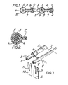
- the cable comprises a plurality of seven strand signal conductors 1 and a corresponding individually associated plurality of seven strand ground conductors 2.
- Each signal conductor 1 is surrounded by an inner layer 3 of insulating plastics material, which is in turn surrounded by a shielding layer 4 formed, for example, of an aluminium foil.
- the shielding layer 4 is in turn surrounded by an outer layer 5 of insulating plastics material.
- the signal and ground conductors 1 and 2 are alternately arranged in spaced parallel relationship in a planar array, the spacing between adjacent conductors being equal to the spacing between adjacent contacts in a connector to be used to terminate the cable (as illustrated in Figure 3).
- Each ground conductor 2 is surrounded by the shielding layer 4 which is in electrical contact therewith, the shielding layer 4 in turn being surrounded by an outer layer 6 of insulating plastics material.
- the outer layer 5 of insulating material surrounding each signal conductor 1 and the outer layer 6 of insulating material surrounding the associated ground conductor 2 are joined by a web 7 through which the shielding layer 4 extends.
- outer layers 5 and 6 of insulating material and the web 7 are integrally formed and each pair of signal and ground conductors 1 and 2 is joined to the adjacent pair or pairs by a further web 8 of insulating material also integrally formed with the layers 5 and 6 and the web 7.
- each pair of signal and ground conductors 1 and 2 serves to shield the signal conductor 1 throughout its length, and can easily be terminated at a connector in a similar manner to the signal conductor 1 by means of the ground conductor 2 which is electrically connected thereto.
- Figure 3 shows an end portion of a cable as shown in Figures 1 and 2 prepared for-_termination by means of a connector (not shown in detail) having contacts with slotted plate portions 10 each having a slot 11 into which a conductor can be urged transversely of its axis.
- the outer layer 5 of insulating material and the shielding layer 4 have been removed from a length of the signal conductor 1 to leave the conductor 1 with the inner layer 3 of insulating material thereon substantially equal in diameter to the diameter of the ground conductor 2 with the surrounding shielding layer 4 and outer layer 6 of insulating material.
- the web 7 with the shielding layer 4 therein has also been removed from between the signal and ground conductors 1 and 2, as has the web 8 between adjacent pairs of associates signal and ground conductors 1 and 2.
- the cable can thus be terminated using conventional mass termination apparatus (not shown) and using a connector having contacts with identical slotted plate contact portions 10 as shown.
- the cable of this invention can be manufactured using known extrusion techniques which do not require detailed description herein.
Landscapes
- Physics & Mathematics (AREA)
- Electromagnetism (AREA)
- Insulated Conductors (AREA)
- Communication Cables (AREA)
- Coupling Device And Connection With Printed Circuit (AREA)
- Multi-Conductor Connections (AREA)
Priority Applications (1)
| Application Number | Priority Date | Filing Date | Title |
|---|---|---|---|
| AT82302911T ATE13605T1 (de) | 1981-06-18 | 1982-06-07 | Abgeschirmtes elektrisches kabel. |
Applications Claiming Priority (2)
| Application Number | Priority Date | Filing Date | Title |
|---|---|---|---|
| GB8118727 | 1981-06-18 | ||
| GB8118727 | 1981-06-18 |
Publications (2)
| Publication Number | Publication Date |
|---|---|
| EP0068665A1 true EP0068665A1 (fr) | 1983-01-05 |
| EP0068665B1 EP0068665B1 (fr) | 1985-05-29 |
Family
ID=10522592
Family Applications (1)
| Application Number | Title | Priority Date | Filing Date |
|---|---|---|---|
| EP82302911A Expired EP0068665B1 (fr) | 1981-06-18 | 1982-06-07 | Câble électrique blindé |
Country Status (7)
| Country | Link |
|---|---|
| US (1) | US4490574A (fr) |
| EP (1) | EP0068665B1 (fr) |
| JP (1) | JPS581919A (fr) |
| AT (1) | ATE13605T1 (fr) |
| CA (1) | CA1174308A (fr) |
| DE (1) | DE3263865D1 (fr) |
| HK (1) | HK55288A (fr) |
Cited By (3)
| Publication number | Priority date | Publication date | Assignee | Title |
|---|---|---|---|---|
| EP0073622A3 (fr) * | 1981-08-24 | 1983-07-27 | W.L. GORE & ASSOCIATES, INC. | Ensemble de câbles coaxiaux multiconducteurs |
| EP0103430A1 (fr) * | 1982-09-11 | 1984-03-21 | AMP INCORPORATED (a New Jersey corporation) | Câble électrique blindé |
| DE3540397A1 (de) * | 1985-11-14 | 1987-05-21 | Lacroix & Kress Klasing Gmbh & | Verfahren zum herstellen einer bandleitung und die bandleitung selbst |
Families Citing this family (22)
| Publication number | Priority date | Publication date | Assignee | Title |
|---|---|---|---|---|
| JPS59103315U (ja) * | 1982-12-27 | 1984-07-11 | 日立電線株式会社 | シ−ルド付圧接接続用電線 |
| JPS63191511U (fr) * | 1987-05-28 | 1988-12-09 | ||
| US4972041A (en) * | 1989-07-18 | 1990-11-20 | W. L. Gore & Associates, Inc. | Ribbon cables having wrapped drain wires |
| JPH03103517U (fr) * | 1990-02-09 | 1991-10-28 | ||
| JPH0538717U (ja) * | 1991-08-30 | 1993-05-25 | 東京電線工業株式会社 | シールド電線 |
| US5250753A (en) * | 1992-04-10 | 1993-10-05 | The United States Of America As Represented By The Secretary Of The Navy | Wire assembly for electrically conductive circuits |
| US5556300A (en) * | 1994-11-14 | 1996-09-17 | The Whitaker Corporation | End connection for a flexible shielded cable conductor |
| US5554825A (en) * | 1994-11-14 | 1996-09-10 | The Whitaker Corporation | Flexible cable with a shield and a ground conductor |
| US7633012B2 (en) * | 2008-03-20 | 2009-12-15 | Tennrich International Corp. | Structure for flexible flat cable |
| US9685259B2 (en) | 2009-06-19 | 2017-06-20 | 3M Innovative Properties Company | Shielded electrical cable |
| EP2443633B1 (fr) | 2009-06-19 | 2017-09-13 | 3M Innovative Properties Company | Câble électrique blindé |
| JP2011014391A (ja) * | 2009-07-02 | 2011-01-20 | Yazaki Corp | 金属箔巻きシールド電線 |
| EP2889881A1 (fr) | 2010-08-31 | 2015-07-01 | 3M Innovative Properties Company | Câble électrique blindé |
| BR112013003047A2 (pt) | 2010-08-31 | 2016-06-14 | 3M Innovative Properties Co | cabo elétrico blindado com espaçamento dielétrico |
| US12205732B2 (en) | 2010-08-31 | 2025-01-21 | 3M Innovative Properties Company | Shielded electric cable |
| WO2012030365A1 (fr) * | 2010-08-31 | 2012-03-08 | 3M Innovative Properties Company | Câble électrique blindé à haute densité et autres câbles blindés, systèmes et procédés |
| US10147522B2 (en) | 2010-08-31 | 2018-12-04 | 3M Innovative Properties Company | Electrical characteristics of shielded electrical cables |
| JP5755324B2 (ja) | 2010-08-31 | 2015-07-29 | スリーエム イノベイティブ プロパティズ カンパニー | 遮蔽電気ケーブルの電気的特性 |
| BR112013003296A2 (pt) | 2010-08-31 | 2016-06-07 | 3M Innovatie Properties Company | cabo elétrico blindado e montagem de cabo |
| JP2013543635A (ja) | 2010-09-23 | 2013-12-05 | スリーエム イノベイティブ プロパティズ カンパニー | 遮蔽された電気ケーブル |
| US10964448B1 (en) * | 2017-12-06 | 2021-03-30 | Amphenol Corporation | High density ribbon cable |
| DE102018104253B4 (de) * | 2018-02-26 | 2019-12-05 | Rosenberger Hochfrequenztechnik Gmbh & Co. Kg | Steckverbinderanordnung |
Citations (4)
| Publication number | Priority date | Publication date | Assignee | Title |
|---|---|---|---|---|
| US3775552A (en) * | 1971-12-16 | 1973-11-27 | Amp Inc | Miniature coaxial cable assembly |
| DE2547152A1 (de) * | 1975-10-21 | 1977-04-28 | Tenge Hans Werner | Elektrische abschirmung von kabeln und leitungen und verfahren zu ihrer herstellung |
| GB2047947A (en) * | 1979-04-23 | 1980-12-03 | Molex Inc | Shield Flat Cable |
| EP0059005A1 (fr) * | 1981-02-20 | 1982-09-01 | Koninklijke Philips Electronics N.V. | Câble électrique pour la transmission de signaux |
Family Cites Families (7)
| Publication number | Priority date | Publication date | Assignee | Title |
|---|---|---|---|---|
| CA697919A (en) * | 1964-11-17 | Pirelli Cables, Conduits Limited | Electrical conducting wires | |
| US2043044A (en) * | 1935-03-05 | 1936-06-02 | Gen Electric | Electric cable |
| JPS5491790A (en) * | 1977-12-29 | 1979-07-20 | Junkosha Co Ltd | Flat cable |
| US4234759A (en) * | 1979-04-11 | 1980-11-18 | Carlisle Corporation | Miniature coaxial cable assembly |
| US4383725A (en) * | 1979-06-14 | 1983-05-17 | Virginia Patent Development Corp. | Cable assembly having shielded conductor |
| US4374299A (en) * | 1980-05-19 | 1983-02-15 | Belden Corporation | Triboelectric transducer cable |
| US4412092A (en) * | 1981-08-24 | 1983-10-25 | W. L. Gore & Associates, Inc. | Multiconductor coaxial cable assembly and method of fabrication |
-
1982
- 1982-06-07 DE DE8282302911T patent/DE3263865D1/de not_active Expired
- 1982-06-07 EP EP82302911A patent/EP0068665B1/fr not_active Expired
- 1982-06-07 AT AT82302911T patent/ATE13605T1/de not_active IP Right Cessation
- 1982-06-08 CA CA000404719A patent/CA1174308A/fr not_active Expired
- 1982-06-17 JP JP57103144A patent/JPS581919A/ja active Pending
-
1983
- 1983-12-13 US US06/561,129 patent/US4490574A/en not_active Expired - Lifetime
-
1988
- 1988-07-21 HK HK552/88A patent/HK55288A/en not_active IP Right Cessation
Patent Citations (4)
| Publication number | Priority date | Publication date | Assignee | Title |
|---|---|---|---|---|
| US3775552A (en) * | 1971-12-16 | 1973-11-27 | Amp Inc | Miniature coaxial cable assembly |
| DE2547152A1 (de) * | 1975-10-21 | 1977-04-28 | Tenge Hans Werner | Elektrische abschirmung von kabeln und leitungen und verfahren zu ihrer herstellung |
| GB2047947A (en) * | 1979-04-23 | 1980-12-03 | Molex Inc | Shield Flat Cable |
| EP0059005A1 (fr) * | 1981-02-20 | 1982-09-01 | Koninklijke Philips Electronics N.V. | Câble électrique pour la transmission de signaux |
Cited By (3)
| Publication number | Priority date | Publication date | Assignee | Title |
|---|---|---|---|---|
| EP0073622A3 (fr) * | 1981-08-24 | 1983-07-27 | W.L. GORE & ASSOCIATES, INC. | Ensemble de câbles coaxiaux multiconducteurs |
| EP0103430A1 (fr) * | 1982-09-11 | 1984-03-21 | AMP INCORPORATED (a New Jersey corporation) | Câble électrique blindé |
| DE3540397A1 (de) * | 1985-11-14 | 1987-05-21 | Lacroix & Kress Klasing Gmbh & | Verfahren zum herstellen einer bandleitung und die bandleitung selbst |
Also Published As
| Publication number | Publication date |
|---|---|
| ATE13605T1 (de) | 1985-06-15 |
| DE3263865D1 (en) | 1985-07-04 |
| CA1174308A (fr) | 1984-09-11 |
| EP0068665B1 (fr) | 1985-05-29 |
| HK55288A (en) | 1988-07-29 |
| US4490574A (en) | 1984-12-25 |
| JPS581919A (ja) | 1983-01-07 |
Similar Documents
| Publication | Publication Date | Title |
|---|---|---|
| EP0103430B1 (fr) | Câble électrique blindé | |
| EP0068665B1 (fr) | Câble électrique blindé | |
| US4406512A (en) | Triple row coax cable connector | |
| US4365856A (en) | Electric connector for coaxial ribbon cable | |
| US4680423A (en) | High performance flat cable | |
| EP0002367B1 (fr) | Assemblage des connecteurs terminaux pour câbles plats et flexibles | |
| CA1286738C (fr) | Cable coaxial | |
| JP3260759B2 (ja) | ケーブル終端接続用ワイヤマネイジメントアダプタ | |
| US4701139A (en) | Shielded cable assembly | |
| KR920020786A (ko) | 동축 케이블 커넥터 | |
| US4624515A (en) | Electrical connector with grounding clip | |
| EP0125760A1 (fr) | Connecteur à broches ayant une enveloppe blindée | |
| EP0074205B1 (fr) | Connecteur pour un câble coaxial blindé | |
| CA1140227A (fr) | Methode de terminaison de cable electrique blinde et ensemble comprenant un connecteur terminant un tel cable | |
| US5091610A (en) | High impedance electrical cable | |
| CA2051505C (fr) | Cable electrique a grande impedance et methode de formage | |
| US3909506A (en) | Coxial cable connector and method therefor | |
| EP0163361B1 (fr) | Connecteur électrique pour des câbles coaxiaux | |
| EP0022609B1 (fr) | Connecteur électrique et procédé pour assembler un câble coaxial à ce connecteur | |
| US4701137A (en) | Electrical connector for coaxial cables | |
| KR890004399B1 (ko) | 케이블 접속기 | |
| EP0123417A2 (fr) | Câble-ruban électrique sans entailles | |
| US5811735A (en) | Fine pitch flat cable having improved connector alignment profile | |
| EP0388545B1 (fr) | Faisceau de câble | |
| US5049215A (en) | Method of forming a high impedance electrical cable |
Legal Events
| Date | Code | Title | Description |
|---|---|---|---|
| PUAI | Public reference made under article 153(3) epc to a published international application that has entered the european phase |
Free format text: ORIGINAL CODE: 0009012 |
|
| AK | Designated contracting states |
Designated state(s): AT BE CH DE FR GB IT LI NL SE |
|
| 17P | Request for examination filed |
Effective date: 19830414 |
|
| ITF | It: translation for a ep patent filed | ||
| GRAA | (expected) grant |
Free format text: ORIGINAL CODE: 0009210 |
|
| AK | Designated contracting states |
Designated state(s): AT BE CH DE FR GB IT LI NL SE |
|
| REF | Corresponds to: |
Ref document number: 13605 Country of ref document: AT Date of ref document: 19850615 Kind code of ref document: T |
|
| REF | Corresponds to: |
Ref document number: 3263865 Country of ref document: DE Date of ref document: 19850704 |
|
| ET | Fr: translation filed | ||
| PLBE | No opposition filed within time limit |
Free format text: ORIGINAL CODE: 0009261 |
|
| STAA | Information on the status of an ep patent application or granted ep patent |
Free format text: STATUS: NO OPPOSITION FILED WITHIN TIME LIMIT |
|
| 26N | No opposition filed | ||
| ITTA | It: last paid annual fee | ||
| REG | Reference to a national code |
Ref country code: GB Ref legal event code: 732E |
|
| EAL | Se: european patent in force in sweden |
Ref document number: 82302911.1 |
|
| PGFP | Annual fee paid to national office [announced via postgrant information from national office to epo] |
Ref country code: SE Payment date: 19950516 Year of fee payment: 14 |
|
| PGFP | Annual fee paid to national office [announced via postgrant information from national office to epo] |
Ref country code: AT Payment date: 19950523 Year of fee payment: 14 |
|
| PGFP | Annual fee paid to national office [announced via postgrant information from national office to epo] |
Ref country code: CH Payment date: 19950620 Year of fee payment: 14 |
|
| PGFP | Annual fee paid to national office [announced via postgrant information from national office to epo] |
Ref country code: BE Payment date: 19950626 Year of fee payment: 14 |
|
| PGFP | Annual fee paid to national office [announced via postgrant information from national office to epo] |
Ref country code: GB Payment date: 19960509 Year of fee payment: 15 |
|
| PG25 | Lapsed in a contracting state [announced via postgrant information from national office to epo] |
Ref country code: AT Effective date: 19960607 |
|
| PG25 | Lapsed in a contracting state [announced via postgrant information from national office to epo] |
Ref country code: SE Effective date: 19960608 |
|
| PG25 | Lapsed in a contracting state [announced via postgrant information from national office to epo] |
Ref country code: LI Effective date: 19960630 Ref country code: CH Effective date: 19960630 Ref country code: BE Effective date: 19960630 |
|
| BERE | Be: lapsed |
Owner name: AMP INC. (UNE SOC. DE PENNSYLVANIE) Effective date: 19960630 |
|
| REG | Reference to a national code |
Ref country code: CH Ref legal event code: PL |
|
| EUG | Se: european patent has lapsed |
Ref document number: 82302911.1 |
|
| PG25 | Lapsed in a contracting state [announced via postgrant information from national office to epo] |
Ref country code: GB Free format text: LAPSE BECAUSE OF NON-PAYMENT OF DUE FEES Effective date: 19970607 |
|
| GBPC | Gb: european patent ceased through non-payment of renewal fee |
Effective date: 19970607 |
|
| PGFP | Annual fee paid to national office [announced via postgrant information from national office to epo] |
Ref country code: NL Payment date: 19990322 Year of fee payment: 18 |
|
| PGFP | Annual fee paid to national office [announced via postgrant information from national office to epo] |
Ref country code: FR Payment date: 20000602 Year of fee payment: 19 |
|
| PG25 | Lapsed in a contracting state [announced via postgrant information from national office to epo] |
Ref country code: NL Free format text: LAPSE BECAUSE OF NON-PAYMENT OF DUE FEES Effective date: 20010101 |
|
| NLV4 | Nl: lapsed or anulled due to non-payment of the annual fee |
Effective date: 20010101 |
|
| PGFP | Annual fee paid to national office [announced via postgrant information from national office to epo] |
Ref country code: DE Payment date: 20011228 Year of fee payment: 20 |
|
| PG25 | Lapsed in a contracting state [announced via postgrant information from national office to epo] |
Ref country code: FR Free format text: LAPSE BECAUSE OF NON-PAYMENT OF DUE FEES Effective date: 20020228 |