EP0068687A1 - Schrumpfbarer Gegenstand - Google Patents
Schrumpfbarer Gegenstand Download PDFInfo
- Publication number
- EP0068687A1 EP0068687A1 EP82303021A EP82303021A EP0068687A1 EP 0068687 A1 EP0068687 A1 EP 0068687A1 EP 82303021 A EP82303021 A EP 82303021A EP 82303021 A EP82303021 A EP 82303021A EP 0068687 A1 EP0068687 A1 EP 0068687A1
- Authority
- EP
- European Patent Office
- Prior art keywords
- article
- substrate
- recoverable
- connector
- axis
- Prior art date
- Legal status (The legal status is an assumption and is not a legal conclusion. Google has not performed a legal analysis and makes no representation as to the accuracy of the status listed.)
- Withdrawn
Links
- 238000011084 recovery Methods 0.000 claims abstract description 14
- 229910000679 solder Inorganic materials 0.000 claims abstract description 12
- 230000000694 effects Effects 0.000 claims abstract description 6
- 239000000758 substrate Substances 0.000 claims description 27
- 239000000463 material Substances 0.000 claims description 14
- 238000000034 method Methods 0.000 claims description 6
- 238000003780 insertion Methods 0.000 claims description 2
- 230000037431 insertion Effects 0.000 claims description 2
- 239000004020 conductor Substances 0.000 abstract description 31
- 238000004519 manufacturing process Methods 0.000 description 6
- RYGMFSIKBFXOCR-UHFFFAOYSA-N Copper Chemical compound [Cu] RYGMFSIKBFXOCR-UHFFFAOYSA-N 0.000 description 3
- 229910052802 copper Inorganic materials 0.000 description 3
- 239000010949 copper Substances 0.000 description 3
- 238000010438 heat treatment Methods 0.000 description 3
- 230000000717 retained effect Effects 0.000 description 2
- 239000000853 adhesive Substances 0.000 description 1
- 230000001070 adhesive effect Effects 0.000 description 1
- 230000015572 biosynthetic process Effects 0.000 description 1
- 238000010924 continuous production Methods 0.000 description 1
- 238000001816 cooling Methods 0.000 description 1
- 238000004132 cross linking Methods 0.000 description 1
- 238000005538 encapsulation Methods 0.000 description 1
- 230000002708 enhancing effect Effects 0.000 description 1
- 230000001747 exhibiting effect Effects 0.000 description 1
- 230000004907 flux Effects 0.000 description 1
- 238000005304 joining Methods 0.000 description 1
- 210000001503 joint Anatomy 0.000 description 1
- 230000014759 maintenance of location Effects 0.000 description 1
- 239000000155 melt Substances 0.000 description 1
- 238000002844 melting Methods 0.000 description 1
- 230000008018 melting Effects 0.000 description 1
- 229920000642 polymer Polymers 0.000 description 1
- 238000007493 shaping process Methods 0.000 description 1
- 230000001052 transient effect Effects 0.000 description 1
Images
Classifications
-
- H—ELECTRICITY
- H01—ELECTRIC ELEMENTS
- H01R—ELECTRICALLY-CONDUCTIVE CONNECTIONS; STRUCTURAL ASSOCIATIONS OF A PLURALITY OF MUTUALLY-INSULATED ELECTRICAL CONNECTING ELEMENTS; COUPLING DEVICES; CURRENT COLLECTORS
- H01R4/00—Electrically-conductive connections between two or more conductive members in direct contact, i.e. touching one another; Means for effecting or maintaining such contact; Electrically-conductive connections having two or more spaced connecting locations for conductors and using contact members penetrating insulation
- H01R4/70—Insulation of connections
- H01R4/72—Insulation of connections using a heat shrinking insulating sleeve
- H01R4/723—Making a soldered electrical connection simultaneously with the heat shrinking
-
- B—PERFORMING OPERATIONS; TRANSPORTING
- B29—WORKING OF PLASTICS; WORKING OF SUBSTANCES IN A PLASTIC STATE IN GENERAL
- B29C—SHAPING OR JOINING OF PLASTICS; SHAPING OF MATERIAL IN A PLASTIC STATE, NOT OTHERWISE PROVIDED FOR; AFTER-TREATMENT OF THE SHAPED PRODUCTS, e.g. REPAIRING
- B29C61/00—Shaping by liberation of internal stresses; Making preforms having internal stresses; Apparatus therefor
- B29C61/06—Making preforms having internal stresses, e.g. plastic memory
- B29C61/0608—Making preforms having internal stresses, e.g. plastic memory characterised by the configuration or structure of the preforms
-
- Y—GENERAL TAGGING OF NEW TECHNOLOGICAL DEVELOPMENTS; GENERAL TAGGING OF CROSS-SECTIONAL TECHNOLOGIES SPANNING OVER SEVERAL SECTIONS OF THE IPC; TECHNICAL SUBJECTS COVERED BY FORMER USPC CROSS-REFERENCE ART COLLECTIONS [XRACs] AND DIGESTS
- Y10—TECHNICAL SUBJECTS COVERED BY FORMER USPC
- Y10S—TECHNICAL SUBJECTS COVERED BY FORMER USPC CROSS-REFERENCE ART COLLECTIONS [XRACs] AND DIGESTS
- Y10S439/00—Electrical connectors
- Y10S439/932—Heat shrink material
Definitions
- This invention relates to recoverable articles, and is particularly though not exclusively concerned with recoverable, preferably heat-recoverable, articles for connecting electrical conductors together.
- a “recoverable” article is one whose dimensional configuration may be made to change when subjected to an appropriate treatment. Usually these articles recover towards an original shape from which they have previously been deformed but the term "recoverable”, as used herein, also includes an article which adopts a_new configuration, even if it has not been previously deformed.
- the article may be heat recoverable, such that its dimensional configuration may be made to- change when subjected to heat treatment.
- such articles comprise a heat- shrinkable sleeve made from a polymeric material exhibiting the property of elastic or plastic memory as described, for example, in US Patent Nos.2027962; 3086242 and 3957372, the disclosures of which are herein incorporated by this reference.
- the original dimensionally heat-stable form may be a transient form in a continuous process in which, for example, an extruded tube is expanded, whilst hot, to a dimensionally heat-unstable form but, in other applications, a preformed dimensionally heat stable article is deformed to a dimensionally heat unstable form in a separate stage.
- the polymeric material may D e cross-linked at. any stage in the production cf the article that will enhance the desired dimensional recoverability.
- One manner of producing a heat-recoverable article comprises shaping the polymeric material into the desired heat-stable form, subsequently cross-linking the polymeric material, heating the article to a temperature above the crystalline melting point or,for amorphous materials the softening point, as the case may be, of the polymer, deforming the article and cooling the article whilst in the deformed state so that the deformed state of the article is retained.
- application of heat will cause the article to assume its original heat-stable shape.
- an elastomeric member such as an outer tubular member is held in a stretched state by a second member, such as an inner tubular member, which upon heating weakens and thus allows the elastomeric member to recover.
- Heat-recoverable electrical connectors are known, from UK Patent Specification No 1062043 and pending UK Patent Application Publication No 2027561A, for example, that comprise a heat-recoverable substantially cylindrical tube of polymeric material that is open at each end and a quantity of solder disposed therein.
- two end stripped conductors to be joined together are introduced axially into respective ends of the connector so as to be disposed adjacent the solder.
- the connector is then heated,the tube recovers, in this case by contracting towards a substantially smaller diameter configuration, thereby to enclose the conductors, and the solder melts and forms an electrical connection between them.
- mechanical encapsulation and electrical interconnection are conveniently provided by a single operation.
- Such connectors have found wide application, not only for making discrete connections; but alsc for simultaneously terminating a plurality of conductors on to pins of a multi-pin connector, as disclosed in US patent No 3945114 and UK Patent Publication No 2070469A.
- the arrangements disclosed in these specifications operate semi-automatically, in particular axial alignment between the conductors to be joined by the connector is effected automatically.
- British Patent Specifiation No. 1359704 discloses a heat-recoverable article that is arranged to provide, on recovery, an L-shaped insulating cover for a flag-type electrical terminal assembly.
- the flag terminal extending perpendicularly to the side of the conductor to which it is attached, is inserted axially as a close fit into a tubular portion of the article, thus requiring precise location with respect thereto.
- a recoverable article having in its recovered state an axis along which, in operation, is disposed an elongate substrate, and having in its recoverable state an opening that is arranged to receive, in operation, the elongate'substrate translationally from a direction generally perpendicular to said axis, the article being arranged to have a component cf its recovery movement towards the substrate in the direction generally perpendicularly of said axis, thereby, in operation, to enclose the substrate.
- An article in accordance with the invention thus allows an elongate substrate, for example, an electrical conductor, to be inserted therein by a translational movement, that is to say by a movement in a plane that includes, or is substantially parallel to a plane that includes, said axis, thus avoiding the necessity of accurate axial alignment of the substrate with an aperture that lies in a plane that extends substantially perpendicular to said axis.
- a translational movement that is to say by a movement in a plane that includes, or is substantially parallel to a plane that includes, said axis
- the article may comprise at least one further opening that is similar to said opening. Furthermore, the article may comprise a plurality of pairs-of said openings in side-by-side relationship, each pair of openings being arranged substantially axially to receive respective ones of substrates, for example electrical conductors, that are to be connected together.
- the article may be of generally tubular configuration, which is to be understood to include L, Y, and V shapes as well as generally cylindrically shapes, and at least part of the tubular configuration, before recovery, may include the said axis.
- the article has a substantially closed cross-section.
- substantially the whole of the article comprises recoverable material, preferably heat-recoverable material, and most preferably heat-recoverable polymeric material.
- electrically conductive means which may comprise solder, including any necessary flux, for enhancing electrical connection.
- Said means may alternatively, or additionally, comprise a metallic strip, preferably having solder mounted thereon.
- the article of the present invention may be manufactured as the article described in above-mentioned UK Patent Specification No 1062043 (the disclosure of which is herein incorporated by this reference), which method is particularly advantageous for manufacturing single articles, particularly those of generally tubular configuration and having solder inserted therein.
- manufacture may advantageously be made in accordance with UK Patent Publication Nos 2082110A, 2083859A, 2084505A, 2083403A, or US Patent Application Serial No 172897, the disclosures of which are herein incorporated by this reference.
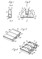
- a heat-recoverable connector 2 is formed from heat-recoverable polymeric material.
- the connector 2 was initially formed as a substantially cylindrical tubular article open at each end, the two ends of which were subsequently deformed away from its axis to provide two portions 4, 6 extending upwardly, for example generally perpendicularly, thereto.
- the deformed end portions 4, 6 are spaced inwardly of respective ends of the connector 2 so as to provide openings 8, 10 that extend not only axially of the connector 2 but also perpendicularly upwardly therefrom.
- a generally rectangular-sectioned copper strip 12 is located at the bottom of the connector 2 extending into both openings 8, 10, and a ring of solder 14 is retained in the central, closed cross-section, portion 16 of the connector 2.
- the connector 2 is particularly suited for joining together two elongate conductors 18.
- the upwardly-directed openings 8, 10 allow the conductors 18 to be inserted into respective ends of the connector 2 from- a generally downward direction indicated by arrows A, into the positions shown, without the necessity of precise axial alignment, and in particular without the necessity of precise axial introduction of the conductors into the tubular central connector portion 16.
- the insertion of the conductors 18 may conveniently be carried out by a translational motion in a substantially vertical plane. After the conductors 18 have been introduced into the connector 2 to the position shown in Figure 2, it is, of course, possible for them subsequently to be slid axially towards each other so as to dispose their stripped end portions within the solder ring 14.
- the axis of the connector 2 lies substantially along the axis of the two conductors 18, which have been brought into such position by movement in a direction, indicated by the arrows A generally perpendicular to said axis.
- the connectors 2 may be supplied individually, or, where appropriate, may be attached individually to a backing strip, for example, by adhesive, and supplied in an elongate strip, as in a bandolier.
- the connector 19 of Figures 3 and 4 comprises a sheet 20 of cross-linked polymeric material that is secured; for example, by weld lines 22 to another sheet 24 of cross-linked polymeric material of castellated configuration, so as to provide a plurality of-generally cylindrical enclosures 26 therebetween in side-by-side relationship.
- the sheet 24 is recoverable so as to reduce the transverse size of the enclosures 26.
- the sheet 20 thereof is deformed from the planar configuration shown in Figure 3, to that shown in Figure 4, whereby the portions at each end of the enclosures 26 are stretched upwardly and pulled axially inwardly so as to provide openings 28 that are directed substantially perpendicularly with respect to the axes of the tubular enclosures 26.
- the enclosures 26 are provided either by the stage of manufacture shown in Figure 3, or in its ultimate formation as shown in Figure 4, with conductive strips 30 and portions of solder (not shown) as described with reference to the embodiment of Figures 1 and 2.
- the connector of Figures 3 and 4 has the - advantages and method of use as described above with reference to Figures 1 and 2.
- the connector produced may arrange for interconnecting any required number of pairs and gauges of conductors.
- the connector of Figures 3 and 4 may be cut along the weld lines 22 to provide a plurality of separate connectors for interconnecting individual pairs of conductors.
- the connector 2 or 19 may have the enclosures thereof sealed along the lines C-C and D-D for Figures 2 and 4 respectively and be cut in two so as conveniently to provide a connector for forming a butt joint between conductors inserted through the same opening generally from the same direction.
- the folded back portions thereof may be secured together temporarily. This may be done by a welded joint that is arranged to be broken on treating the article to effect recovery thereof.
Landscapes
- Insulating Bodies (AREA)
- Cable Accessories (AREA)
- Shaping By String And By Release Of Stress In Plastics And The Like (AREA)
- Lining Or Joining Of Plastics Or The Like (AREA)
Applications Claiming Priority (2)
| Application Number | Priority Date | Filing Date | Title |
|---|---|---|---|
| GB8119347 | 1981-06-23 | ||
| GB8119347 | 1981-06-23 |
Publications (1)
| Publication Number | Publication Date |
|---|---|
| EP0068687A1 true EP0068687A1 (de) | 1983-01-05 |
Family
ID=10522749
Family Applications (1)
| Application Number | Title | Priority Date | Filing Date |
|---|---|---|---|
| EP82303021A Withdrawn EP0068687A1 (de) | 1981-06-23 | 1982-06-11 | Schrumpfbarer Gegenstand |
Country Status (4)
| Country | Link |
|---|---|
| US (1) | US4514031A (de) |
| EP (1) | EP0068687A1 (de) |
| JP (1) | JPS585980A (de) |
| GB (1) | GB2101424A (de) |
Families Citing this family (2)
| Publication number | Priority date | Publication date | Assignee | Title |
|---|---|---|---|---|
| JPS6189006A (ja) * | 1984-10-08 | 1986-05-07 | 株式会社ノリタケカンパニーリミテド | 陶磁器食器類坏土のロクロ回転式圧延成形法及び回転成形鏝 |
| US4789349A (en) * | 1987-02-04 | 1988-12-06 | General Dynamics Corp./Space Systems Division | Thermal contraction conductor joint |
Citations (4)
| Publication number | Priority date | Publication date | Assignee | Title |
|---|---|---|---|---|
| US3396460A (en) * | 1962-07-23 | 1968-08-13 | Raychem Corp | Method of making a connection |
| US3662094A (en) * | 1970-07-06 | 1972-05-09 | Raychem Corp | Heat recoverable insulating cover for electrical terminal, and method of manufacture |
| US3678174A (en) * | 1971-01-15 | 1972-07-18 | Raychem Corp | Self-locking heat shrinkable insulating sleeve |
| US3721749A (en) * | 1970-11-16 | 1973-03-20 | Rachem Corp | Heat recoverable articles |
Family Cites Families (18)
| Publication number | Priority date | Publication date | Assignee | Title |
|---|---|---|---|---|
| US2027962A (en) * | 1933-03-03 | 1936-01-14 | Nat Carbon Co Inc | Production of articles from plastic compositions |
| NL130678C (de) * | 1960-07-15 | 1900-01-01 | ||
| BE635318A (de) * | 1962-07-23 | |||
| US3525799A (en) * | 1968-05-17 | 1970-08-25 | Raychem Corp | Heat recoverable connector |
| US3925596A (en) * | 1972-06-12 | 1975-12-09 | Raychem Corp | Heat recoverable connectors |
| US4035534A (en) * | 1972-09-01 | 1977-07-12 | Raychem Corporation | Heat-shrinkable laminate |
| US3945114A (en) * | 1974-02-14 | 1976-03-23 | Raychem Corporation | Method for the simultaneous termination in terminal sleeves of a plurality of wires with a multi-pin connector |
| US3957372A (en) * | 1974-12-19 | 1976-05-18 | United Technologies Corporation | Vehicle exhaust gas analysis system |
| GB1580210A (en) * | 1975-12-29 | 1980-11-26 | Raychem Corp | Connector |
| US4196308A (en) * | 1976-01-28 | 1980-04-01 | Raychem Corporation | Insulated crimp splicer |
| GB1599997A (en) * | 1977-01-24 | 1981-10-14 | Raychem Ltd | Coil connector |
| GB1600000A (en) * | 1977-01-24 | 1981-10-14 | Raychem Ltd | Memory metal member |
| GB1599998A (en) * | 1977-01-24 | 1981-10-14 | Raychem Ltd | Dimensionally recoverable articles |
| GB1599999A (en) * | 1977-01-24 | 1981-10-14 | Raychem Ltd | Heat-recoverable articles |
| GB2070469B (en) * | 1980-02-29 | 1983-06-08 | Raychem Gmbh | Electrical interconnection |
| DE3175620D1 (en) * | 1980-07-28 | 1987-01-02 | Raychem Ltd | Heat recoverable articles and processes for producing the same |
| ATE5242T1 (de) * | 1980-07-28 | 1983-11-15 | Raychem Limited | Durch waerme schrumpfbare teile und deren herstellungsverfahren. |
| DE3177283T2 (de) * | 1980-07-28 | 1993-02-11 | Raychem Ltd | Warmschrumpfbare gegenstaende. |
-
1982
- 1982-06-11 GB GB08216998A patent/GB2101424A/en not_active Withdrawn
- 1982-06-11 US US06/387,371 patent/US4514031A/en not_active Expired - Fee Related
- 1982-06-11 EP EP82303021A patent/EP0068687A1/de not_active Withdrawn
- 1982-06-23 JP JP57109087A patent/JPS585980A/ja active Pending
Patent Citations (4)
| Publication number | Priority date | Publication date | Assignee | Title |
|---|---|---|---|---|
| US3396460A (en) * | 1962-07-23 | 1968-08-13 | Raychem Corp | Method of making a connection |
| US3662094A (en) * | 1970-07-06 | 1972-05-09 | Raychem Corp | Heat recoverable insulating cover for electrical terminal, and method of manufacture |
| US3721749A (en) * | 1970-11-16 | 1973-03-20 | Rachem Corp | Heat recoverable articles |
| US3678174A (en) * | 1971-01-15 | 1972-07-18 | Raychem Corp | Self-locking heat shrinkable insulating sleeve |
Also Published As
| Publication number | Publication date |
|---|---|
| JPS585980A (ja) | 1983-01-13 |
| US4514031A (en) | 1985-04-30 |
| GB2101424A (en) | 1983-01-12 |
Similar Documents
| Publication | Publication Date | Title |
|---|---|---|
| EP0596993B1 (de) | Wärmeschrumpfbare lötvorrichtung | |
| EP0041857B1 (de) | Lotzufuhr-Vorrichtung | |
| US3316343A (en) | Heat shrinkable connector with preplaced solder therein | |
| EP0037253B1 (de) | Elektrischer Verbinder, sein Herstellungsverfahren und Verfahren zum Herstellen einer Verbindung damit | |
| US4283596A (en) | Connector and connection method | |
| CA1070406A (en) | Connector having heat-recoverable closure member | |
| US4384404A (en) | Heat-recoverable articles and method of connecting two electrical conductors | |
| US4879807A (en) | Method of making a sealed coaxial cable splice | |
| EP0261905B1 (de) | Elektrischer Verbinder und Verfahren zur Verbindung von Adern an diesem | |
| GB1599520A (en) | Heat-recoverable article suitable for making an electrical connection | |
| CA1294682C (en) | Electrical connector | |
| EP0626101B1 (de) | Kabelverbinder | |
| US4514031A (en) | Recoverable article | |
| EP0091319B1 (de) | Vorrichtung zum Verbinden einer Abschirmung | |
| EP0045612B1 (de) | Wärmeschrumpfbarer Verbinder | |
| EP0073103A2 (de) | Verbinder für das elektrische Verbinden eines länglichen Leiters an einen Anschlussposten | |
| US4435454A (en) | Recoverable article | |
| EP0635166B1 (de) | Elektrischer verbinder | |
| GB2096412A (en) | Recoverable article | |
| WO1996003785A1 (en) | Connector |
Legal Events
| Date | Code | Title | Description |
|---|---|---|---|
| PUAI | Public reference made under article 153(3) epc to a published international application that has entered the european phase |
Free format text: ORIGINAL CODE: 0009012 |
|
| 17P | Request for examination filed |
Effective date: 19820629 |
|
| AK | Designated contracting states |
Designated state(s): AT BE CH DE FR IT LI NL SE |
|
| RAP1 | Party data changed (applicant data changed or rights of an application transferred) |
Owner name: RAYCHEM PONTOISE S.A. |
|
| STAA | Information on the status of an ep patent application or granted ep patent |
Free format text: STATUS: THE APPLICATION IS DEEMED TO BE WITHDRAWN |
|
| 18D | Application deemed to be withdrawn |
Effective date: 19841009 |
|
| RIN1 | Information on inventor provided before grant (corrected) |
Inventor name: LIONNET, RICHARD |