EP0068717A2 - Einrichtung zur Kontrolle von chemischen Reaktionen - Google Patents
Einrichtung zur Kontrolle von chemischen Reaktionen Download PDFInfo
- Publication number
- EP0068717A2 EP0068717A2 EP82303116A EP82303116A EP0068717A2 EP 0068717 A2 EP0068717 A2 EP 0068717A2 EP 82303116 A EP82303116 A EP 82303116A EP 82303116 A EP82303116 A EP 82303116A EP 0068717 A2 EP0068717 A2 EP 0068717A2
- Authority
- EP
- European Patent Office
- Prior art keywords
- cartridge
- sample
- radiant energy
- cartridges
- movable carrier
- Prior art date
- Legal status (The legal status is an assumption and is not a legal conclusion. Google has not performed a legal analysis and makes no representation as to the accuracy of the status listed.)
- Withdrawn
Links
Images


Classifications
-
- G—PHYSICS
- G01—MEASURING; TESTING
- G01N—INVESTIGATING OR ANALYSING MATERIALS BY DETERMINING THEIR CHEMICAL OR PHYSICAL PROPERTIES
- G01N21/00—Investigating or analysing materials by the use of optical means, i.e. using sub-millimetre waves, infrared, visible or ultraviolet light
- G01N21/17—Systems in which incident light is modified in accordance with the properties of the material investigated
- G01N21/25—Colour; Spectral properties, i.e. comparison of effect of material on the light at two or more different wavelengths or wavelength bands
- G01N21/251—Colorimeters; Construction thereof
- G01N21/253—Colorimeters; Construction thereof for batch operation, i.e. multisample apparatus
-
- G—PHYSICS
- G01—MEASURING; TESTING
- G01N—INVESTIGATING OR ANALYSING MATERIALS BY DETERMINING THEIR CHEMICAL OR PHYSICAL PROPERTIES
- G01N35/00—Automatic analysis not limited to methods or materials provided for in any single one of groups G01N1/00 - G01N33/00; Handling materials therefor
- G01N35/00029—Automatic analysis not limited to methods or materials provided for in any single one of groups G01N1/00 - G01N33/00; Handling materials therefor provided with flat sample substrates, e.g. slides
- G01N2035/00099—Characterised by type of test elements
- G01N2035/00138—Slides
-
- G—PHYSICS
- G01—MEASURING; TESTING
- G01N—INVESTIGATING OR ANALYSING MATERIALS BY DETERMINING THEIR CHEMICAL OR PHYSICAL PROPERTIES
- G01N35/00—Automatic analysis not limited to methods or materials provided for in any single one of groups G01N1/00 - G01N33/00; Handling materials therefor
- G01N2035/00346—Heating or cooling arrangements
-
- G—PHYSICS
- G01—MEASURING; TESTING
- G01N—INVESTIGATING OR ANALYSING MATERIALS BY DETERMINING THEIR CHEMICAL OR PHYSICAL PROPERTIES
- G01N35/00—Automatic analysis not limited to methods or materials provided for in any single one of groups G01N1/00 - G01N33/00; Handling materials therefor
- G01N35/00584—Control arrangements for automatic analysers
- G01N35/00722—Communications; Identification
- G01N35/00732—Identification of carriers, materials or components in automatic analysers
- G01N2035/00742—Type of codes
- G01N2035/00752—Type of codes bar codes
-
- Y—GENERAL TAGGING OF NEW TECHNOLOGICAL DEVELOPMENTS; GENERAL TAGGING OF CROSS-SECTIONAL TECHNOLOGIES SPANNING OVER SEVERAL SECTIONS OF THE IPC; TECHNICAL SUBJECTS COVERED BY FORMER USPC CROSS-REFERENCE ART COLLECTIONS [XRACs] AND DIGESTS
- Y10—TECHNICAL SUBJECTS COVERED BY FORMER USPC
- Y10T—TECHNICAL SUBJECTS COVERED BY FORMER US CLASSIFICATION
- Y10T436/00—Chemistry: analytical and immunological testing
- Y10T436/11—Automated chemical analysis
- Y10T436/113332—Automated chemical analysis with conveyance of sample along a test line in a container or rack
- Y10T436/114165—Automated chemical analysis with conveyance of sample along a test line in a container or rack with step of insertion or removal from test line
Definitions
- the field of the invention herein is the monitoring by The field of the invention herein is the monitoring by means of radiant energy of the reaction or reactions of chemical specimens and more particularly is concerned with the monitoring of the absorption of radiant energy by specimens of blood, blood fractions or blood serum which have been treated with certain known reagents.
- the purpose of such treatment and monitoring is to ascertain the composition of the blood, blood fraction cr serum quantitatively with respect to certain chemical constituents..
- the information which is derived enables the physician to diagnose illness, ascertain the physical condition of the patient whose blood serum is being tested and determine the efficacy of therapy.
- the so-called automatic chemistry apparatus which has become quite useful and advantageous in being able to assay many of the tests required in modern medicine is based upon the development of many different procedures for testing blood and blood ser- um.
- the technician generally dilutes the serum and adds pne or two or perhaps even three reagents in certain quantities.
- the resulting sample is thoroughly mixed and incubated at a particular temperature or even cooled in certain cases. After a certain amount of time depending upon the nature of the test, the sample acquires a particular color.
- the technician directs the beam from a photometer that produces radiation of a particular wavelength and measures the amount of the radiation which is ab- scrbed by the sample as a measure of a chemical constituent of the serum.
- the advantage of the automatic chemistry apparatus is that a large number of these tests can be conducted in a short time and in the case of a large hospital or testing laboratory the volume of testing required demands seme form of automation.
- the first is the end point of the test and the second is the kinetic progress of the test.
- Automatic chemistry apparatus have been developed and are in use at this time to provide end points, but there have been very few de - vices which enable the determination of the kinetic progress of a reaction.
- the device of said patents includes a turntable with sample support members such as cuvettes that are automatically provided with aliquots of samples, the turntable rotating slowly in a stepping action. After somewhat less than a revolution, in this condition - the samples are removed, the cuvettes washed and tested and other samples introduced, the procedure being a continuous one.
- a rotor carrying a plurality of photometers, eight in the incorporated patents is rotating at a speed greater than that of the turntable, continuously scanning the sample support members but obtaining readings during dwell periods of the stepping movement. Each sample support member is therefore traversed by all of the beams of radiation many times before it has made ,the complete circuit of one revolution'and a considerable amount of data has been obtained.
- This data is fed into a computer which computes the desired results and a readout is obtainable from the memory of the computer.
- the kinetic characteristic of each sample is available in addition to end points, either as a single value representing rate or as a series of values or in a graphic display.
- the sample support members comprise cuvettes which are transparent and that the beams of radiation pass into the cuvettes, through the aliquot or wash water or a blank which may be in the cuvette, out of the cuvette and thence to a photocell which responds to the amount of radiation which is not absorbed by the aliquot or sample.
- the sample must be liquid, although the patents are not necessarily limited to transparent or translucent samples in transparent cuvettes.
- patent 4,234,539 there is disclosed and claimed a . type of automatic chemistry apparatus in which, instead of a rotating turntable of sample support members carrying samples, the sample support members are contained in a carrier which is fixed and does not rotate.
- a carrier could be a disposable article or could be reused. It is intended to be mounted on the apparatus manually and removed when the tests are all completed or the carrier may be fixed and the sample support members individually removed or replaced selectively.
- the same rotor arrangement with multiple photometers is used, rotating at a relatively rapid rate to gain data concerning the aliquots carried in the sample support members or cuvettes of the fixed carrier.
- the rotation rate is abcut ten revolutions per minute.
- This invention also can utilize a circular, arcuate or rectilinear array of samples which is fixed and also a rotor or moving carriage which has a plurality of photometers whose beams scan the samples multiple times for the testing procedure, but apparatus of the invention differs in the manner in which the samples are carried, the data is gathered and in many other respects.
- the / of the invention herein are not arranged for transmission of radiant energy fully through the sample which is preferred by the inventions of the incorporated patents.
- the samples are dispcsed in a manner such that the reaction which occurs therein is measured by reflectance. This will be described in detail hereinafter.
- the invention herein obviates the disadvantages mentioned above.
- the invention as claimed provides:
- the accompanying drawings show /apparatus for monitoring chemical reactions in which the reactions occur on a slide or cartridge which is principally reflective and in which the reaction which occurs is measured quantitatively by detecting, in a photoresponsive device, the change of color of a sample carried on or in the slide, there significant being a beam of radiation directed at the sample and to a/ extent reflected therefrom onto the photoresponsive device.
- the apparatus comprises two principal types of device, rotary and non-rotary.
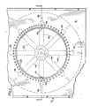
- a fixed support is provided with a circular array of cartridge-holding receptacles,. each having provision for retaining a sample slide or cartridge in measurement position while being identified by suitable means and maintained at a constant temperature.
- a central rotor arranged coaxial with the array carries a plurality of photometers, each providing a radial beam of radiant energy directed to impinge sequentially against the cartridges, the cartridges being tilted to receive the beams and reflect a significant portion of the beams to the photoresponsive devices associated respectively with the photometers.
- Each photometer may be at a different wavelength although for certain purposes one or more may be at the same wavelength.
- the cartridges are inserted through suitable slots in the cover of the apparatus into position in their respective receptacles and the rotor is rotated to derive the data of the reactions. Any cartridge may be inserted or removed at will without disturbing any of the other cartridges and without stopping rotation of the rotor.
- An identifying visible signal may inform the operator when the reaction of a particular cartridge has been measured.
- a fixed support is provided with a linear array of cartridge-holding receptacles, each receptacle having provision for retaining a sample slide or cartridge in measurement position while being identified by suitable means and maintained at a constant temperature.
- the array can be rectilinear or arcuate instead of forming a closed circle.
- a carriage which slides or rolls along a confining track or guideway parallel with the line of disposition of the array, the carriage mounting a single photometer whose primary beam is di - rected to intersect the line of the sample slides when mounted, normal thereto.
- a rotary filter wheel, grating or prism is interposed in the photometer beam.
- the carriage mounts the beam dividing means and photo-responsive means to receive the sub-beams.
- the carriage is driven to step from cartridge to cartridge in a program of movement which will carry it back and forth along its guideway so that it. can make measurements of each slide or cartridge a plurality of times.
- the cartridges are inserted through suitable slots in the cover of the apparatus into position in their respective receptacles and the carriage is stepped along its guideway to derive the data of the reactions. Any cartridge may be inserted or removed at will without disturbing any of the other cartridges and without stopping the travel of the carriage along its guideway.
- the same type of identifying signal may inform the operator when the reaction of a particular has cartridge been measured thus enabling that cartridge to be re - placed while the reactions on other cartridges continue.
- the signals derived from measurements are converted from analog to digital data preferably on the rotor or carriage and multi-plexed to be transmitted to a computer.
- the illustrated apparatus basically comprises a support or fixed part and a driven or moving part.
- the samples which are to be tested are carried on the fixed part in a novel arrangement which disposes them on an angle facing downwardly and the moving part carries the photometer means which direct beams at the samples, the radiant energy being reflected to photoresponsive devices arranged vertically which-gather the information from the samples.
- the apparatus provides identification of the-samples and indication for the operator of the. earliest time that each sample can be removed and replaced by another.
- the top cover 16 has a circular array of slots 20 into which the cartridges which carry samples are to be inserted.
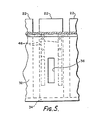
- a cartridge of typical construction is shown in perspective at 22 in Figures 3 and 4 and it is formed as a slide or the like based upon a film or glass substrate 23 that is preferably transparent.
- Each cartridge 22 has a central sample receiving location 24 where the sample of blood serum will be applied.
- the body 25 of the slide is preferably of some liquid impervious material such as waterproof paper or synthetic resin that is nonreactive with the chemicals being used.
- the slide or cartridge 22 is often referred to herein in a generic sense as a sample support member because in the present apparatus it serves the same-purpose as a cuvette in the patents that are incorporated herein by reference.
- the measurements are intended to be transmittance of radiant energy through the sample and/or scattering of radiant energy by the sample.
- the sample which is supported by the sample support member is dry and the measurements made are reflectance and to an extent scatter. Transmittance measurements are not provided for; hence the sample support member and the sample overall may be opaque.
- the radiant energy beam pass through the substrate into the interior of the cartridge, but it passes out of the cartridge by reflectance through the same substrate.
- some forms of cartridge do not utilize a transparent substrate and are not required to transmit any radiant energy through such substrate.
- the central sample receiving location 24 of the cartridge 22 is in the upper surface of a sort of capsule of plural layers or lamina confined in a rectangular well 26 that extends fully through the cartridge body 25 but not through the substrate 23.
- the bottom of the well 26 is therefore closed off by a transparent window 27.
- the capsule which is carried in the well 26 in the illustrated example is formed of the top layer 28 and the central layer 29.
- the top layer is porous but inert and is preferably white. It may contain some type of clay or similar dispersed material such as titanium dioxide and its purpose is to spread the minute quantity of liquid sample that is applied to its exterior and transport it evenly to the central layer 29.
- the central layer 29 is a porous layer also but it contains one or more chemical reagents in dry form that will react when moistened to produce-some typical quantitative reaction identified by a particular color or changing colors There can be several such layers for some reactions.
- the color is "seen" through the window 27 by a beam of radiant energy such as 94 and emerges through the window most significantly as a reflected beam at 94'; modified optically by the color of the reaction. Minor reflections and scattered light represented by the several short broken lines of Figure 4 also emerge butmay not be significant.
- the chemicals in layer 29 are measured so that the application of a specific amount of serum or plasma or even whole blood will produce the quantitative reaction and desired change of color in the layer 29.
- the substrate window 27 of cartridge 22 is transparent or translucent so as to enable a sufficient reach, and leave amount of radiant energy to/be reflected by/the layer 29 when the reaction is occurring and/or has occurred.
- the cartridge 22 / has a bar or other machine-readable code applied at its end 30 which is an identification of the patient from whom the serum sample was taken and could include test instructions. This could be for example on a self-adhering small slip of paper that the technician applies to the vial at bedside, easily removed and transferred to the cartridge when the tests are being conducted. Any other form of identification could be applied at this end 30. Permanent identification of the tests represented by reagents in areas 26 and 28 is preferably applied also at or near the. area 30.
- the slots 20 lead to respective sample chambers 31 within the apparatus 10, the chambers 31 being formed by the conical mask 32 that is connected to cover 16 in the illustration and which has a foot or ledge 34 that provides stop means for the insertion of the cartridges 22.
- the angle of the mask 32 is 45° in order to dispose the cartridges at that angle.
- Each sample chamber 20 is also formed by a small flange 38 which can be connected with the upper cover 16 and could either be individual to each sample chamber 31 or in the form of a frusto-conical depending ring around the line of slots 20.
- Each flange or group of flanges 38 has a heater block 40 which is either engaged through a suitable opening in the flange 38 or is firmly engaged against the rear surface thereof to be in.incubating position relative to a cartridge that may be engaged against the inside surface of the flange 38.
- the heater block 40 is held in position by a small bracket 44 attached to the lower surface of'the top cover 16. Wires 42 extend from the heater block 40 to a control center outside of the apparatus 10 where the incubating temperature of the block Can be chosen.
- a pair of leaf springs 46 is secured to the mask 32 straddling the slit 36 ( see Figure 5) and arranged to press the cartridge 22 inserted into the chamber 31 tightly against the flange 38. This also positions the cartridge 22 accurately for the purposes of measurement. There are partitions between chambers 31 laterally thereof to prevent light scattering or other light interference between them.
- the bar code 30 can be on any convenient surface of the cartridge 22. In Figure 3 it is on the surface to which the layer 28 is exposed, i.e., on the same surface as the sample receiving location 24. When a cartridge is in seated position in its chamber 31, the bar code faces upward at a 45° angle.
- One or more of the photometers has a reader device 48 which can be of any suitable electronic configuration to read the bar code 30 (or other machine-readable code) and transmit the information derived therefrom by means of the leads 50 which extend to the electronic circuitry 52 carried by the rotor 54.
- the partition 56 carried on the support 12 which mounts a motor 58 whose shaft has a first gear 60 that drives the second gear 62 mounted on the rotor '54.
- the rotor 54 has a central passageway 64 in its hollow shaft 66 that is for carrying electrical leads and cables for different purposes.
- the lower extension 68 of the hollow shaft 66 is journalled on the partition 56 by means of a suitable bearing 70.
- the bottom end of the extension 68 engages the rotary part 72 of a slip-ring-connector 74 whose fixed part 76 is mounted to the support 12.
- the rotor 54 has an annular chamber 73 formed by the top wall 80, the hollow shaft 66 and an outer annular wall 82 which provides space for the electronic circuitry 52 that is carried preferably by and rotates with the rotor.
- This circuitry 52 is/ in the form of printed circuit boards carrying electronic and electrical components to process analog signals to digital, co-ordinate the relationships between the signals and the identifying data picked up by the reader devices 48 etc.
- the circuitry 52 has output leads and control leads extended to the rotating part 72 of the slip ring device 74 which has electrical contacts at its upper axial end to which said leads are connected.
- the apparatus 10 which is illustrated in Figures 1 and 2 there are eight photometers and one or more identification reader devices.
- the number of connections which' are required for all of the electrical functions to be transmitted through the slip ring device 74 may be too large for a practical device; hence there is multiplexing of the signal transmission and multiplexing means are provided with the circuitry 52.
- S ym- bolically a block marked "M" is shown at 84 within the hollow passageway 64.
- Each photometer has a source of radiant energy such as a central lamp 86 which is carried on a support 88, the single lamp rotating with the rotor 54 and serving all of the photometers.
- a source of radiant energy such as a central lamp 86 which is carried on a support 88, the single lamp rotating with the rotor 54 and serving all of the photometers.
- There is an optical train for each photometer symbolized by the tube 90 mounted on a pedestal 9.2_carried on the wall 80. The beam from the optical train 90 is shown at 94, entering the slit 36 of the mask 32 passing through window 27 and impinging against the reactive layer 29 of the cartridge 22 disposed on the opposite side of the mask 32.
- the reactive portion of the capsule can comprise several layers or lamina like 29.
- the beam 94 extends horizontally as shown in Figure 2 but inasmuch as the cartridge 22 is disposed at an angle of 45° the reflected beam 94' will be directed downward.
- a platform 96 which is carried by the wall 82 mounts a photoyesponsive device 98 such as a photocell or photodiode which / comprises a photomultiplier with its sensitive receptor element facing up - ward.
- the electrical leads 100 from the device 98 connect to the electronic circuitry 52.
- the reader device 48 is also mounted on this platform 96 to rotate with the rotor 54.
- the arrangement which has been described is compact and simple in construction and provides an apparatus 10 that is simple and effective to use.
- the operator chooses a cartridge 22 to perform the test which is desired.
- This cartridge can provide information for more than a single test 'because there will be eight photometers of different wavelengths illuminating the test area of the cartridge. (Suitable filters can be built into the optical train 90 of each photometer) He applies a small quantity of or other type. of sample serum/to the sample receiving location 24 and inserts the cartridge into an empty slot 20. He moves the cartridge into the . chamber 31 as far as it will go. He may have already instructed the computer and control center what to do.
- the bar code area 30 in addition to giving information about the patient whose serum is being tested will normally also give information to the computer as to what tests are being performed.
- the cartridges can be installed or removed without stopping the rotation of the rotor 54.
- the data output from the apparatus 10 is continuously being passed to the data processing equipment 102 through the leads 104 that connect to the fixed portion 76 of the slip ring device 74. Power for the circuitry 52 and the source of radiant energy 86 is transmitted to the rotor 54 in the same manner from exterior of the apparatus 10.
- the data processing equipment 102 will normally include a computer which will have a memory that can be programmed to perform much of the control of the apparatus.
- the control section is shown at 105.
- the apparatus 10 is capable of providing a signal which will instruct the operator when to remove and replace a cartridge.
- Each of the slots 20 is shown provided with an adjacent signal light l06 , for example, a lamp or a light emitting diode operated under the control of the computer.
- the computer can be instructed that when a particular test is to be carried out, the test will be completed in a set time or when a particular reaction condition has been achieved.
- a signal can be produced which turns on the lamp 106 alongside the slot in which the cartridge is disposed signalling the operator to remove the cartridge can be arranged to and insert another. Removal of the cartridge / trigger resetting of the system in readiness for insertion of the next slide or cartridge.
- the heaters 40 can also be controlled by the computer to provide the exact temperature needed for any particular test or group of tests.
- the bar code can also provide the information needed for the computer to signal the control center 105 to energize the particular heater 40 to some specific temperature and maintain that during the test or tests.
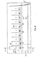
- Figures 6 and 7 illustrate a second embodiment of the invention which aligns the cartridges 22 in a rectilinear disposition.
- the apparatus 10' which is shown utilizes a lesser number of cartridges, can be made smaller and less complex than the apparatus 10 and hence will be less expensive to manufacture.
- the principles of operation and the general construction are quite similar to the apparatus 10.
- the disposition of the cartridges 22 can be in an arc of a circle instead of a complete circle as in apparatus 10 requiring some structural modification over that which will be described for the apparatus 10'.
- the apparatus 10' comprises a frame or housing 120 mounted on a base 122 and having a cover member 124 having an array of slots 126 into which the cartridges 22 are tc be inserted.
- the construction of the cartridges and the manner in which they are used are identical to that already described.
- the slots 126 lead to respective sample chambers 123 within the apparatus 10', the chambers being formed by a depending mask 130 that is connected with the cover member 124 and is in the form of an elongate flange extending the length of the cover member 128.
- the angle of the mask is 45° in order to dispose the cartridges at that angle.
- each slit 136 being aligned with the sample chamber 128 which is to receive a cartridge 22.
- each of the chambers 128 is also formed by a second-flange 138 which is connected with the upper cover member 124 and could either be individual to each sample chamber 128 or in the form of an elongate depending flange extending along the line of the slots 126.
- a heater block such as shewn at 140 is preferably provided for each chamber 128 mounted on or extending through the flange 138 forming each chamber or a group of char-bers.
- flanges 138 there are preferably suitable openings in the flanges 138 to accommodate the heater blocks and thereby enable the heater blocks to serve as incubating means engaged against the cartridge or cartridges 22 or the flange 128 is an elongate unitary structure could have the heater block or blocks 140 snugly engaged against its rear surface in position to warm parts or all of the flange for incubating purposes.
- the electrical wires for the power of the heater blocks 140 extend externally of the apparatus 10' to the control or computer station. Such wires are shown at 142.
- the heater block or blocks 140 are held in position by small brackets 144 which are attached to the lower surface of the cover member 124.
- Partitions 143 are installed between the chambers or receptacles 128 to isolate the chambers 128 from one another optically and thermally.
- the bar code 30 on the surface 25 of the cartridge 22 opposite the surface formed by the substrate 23 faces upward at an angle of 45° when the cartridge 22 is in seated position within a chamber 128.
- a pair of leaf springs 146 in each chamber identical to springs 46 of apparatus 10 will hold the cartridge tightly against the flange 138.
- the bar code 30 can be read by a suitable 'reader device 148 which can be of any electronic configuration to read the bar code 30.
- the reader device 148 is carried by the photometer which shortly will be described and its electrical leads 150 are shown connected to electronics circuitry 152 mounted in a manner which will be described.
- a carriage 154 which has a central section 156, a left hand extension 158 and a right hand extension 160.
- Any suitable arrangement can be used, as for example, rollers on guideways and the like, so long as the carriage 154 is capable of smooth and accurate movement along the line of the slots 126.
- the slides 161 confine and guide the movement of the carriage 154 along the length of the apparatus 10' so that the photometer beam 164 can be brought sequentially into alignment with the slit 136 of each chamber 128.
- the photometer is designated generally 166 and comprises a lamp 168 mounted on the central section 156 of the carriage 154, an optical collimating structure 170 mounted on a suitable bracket 172 and a reflector 174 behind the lamp 168 to concentrate its light to the left as shown in the view.
- a filter wheel 176 is fixed to the shaft of a small motor 178 carried on the central section section 156. Leads are shown connecting the motor 178 and the lamp 168 to the electronics circuitry 152 that is mounted on the extension 160.
- the beam 164 is formed of multiple-wavelengths as the filter wheel is turned and passes through the slit 136, engages into the capsule of the cartridge 22 and is reflected back out at 90° relative to the main beam 164 as shown at 164'.
- a photocell 166 or other photoresponsive device is mounted on the extension 158 along with the bracket 168 that carries the code. reader 148. The leads connected to these devices extend to the electronics circuitry 152.
- the filter wheel 176 there could be prisms or a grating in alignment with the beam 164' so that the reflected beam can be broken up into plural wavelengths.
- the photoresponsive device 166 in such case would be required to have. a plurality of components aligned with the respective beams for responding to the different wavelengths.
- a geared rack 180 engaged with a gear wheel 182 driven by a stepping motor 184 mounted on the base 122.
- the motor is connected by suitable leads to the control console 186 which provides the necessary commands and power to drive the motor 184 so that it is properly positioned and moved for the purposes of the apparatus.
- the carriage 154 carries several different electrical components which require power, control, and which produce signals. These include the reader 148, the photoresponsive device 166 (which may be compound and have the connections for several channels of signals), the lamp 168 and the small motor 178. In addition to these components, the electrical circuitry 152 may include amplifiers, A/ D converters, a multiplexer, etc. The power and control connections are required to be brought out to the computer, .data processing equipment and control console or center 186. This is effected either by a slip contact device or by flexible cables.
- a slip contact.device which has a part 188 that is carried by the carriage 154 and has a plurality of slider members facing slides carried by support 190 extending along the length of the housing 120 to follow the movement of the carriage and provide the necessary electrical contacts. Electrical leads or cables 192 extend to the console 186.
- the device 10' utilizes an economy of parts compared with the apparatus 10.
- the carriage can be instructed to move in a program which will carry it along the length of the slots 126 in one direction, stepping from slot to slot and stopping at each one long enough to make the measurements of the sample carried by the cartridge 22 at each position.
- the carriage can be programmed to return to the first one or it can be programmed to start back-along the positions in reverse.
- the carriage likewise can be programmed to skip any slot where a cartridge has been removed, can be instructed to spend different time durations at different positions, etc.
- the apparatus 10' may be provided with the same type of circuitry for signalling when a reaction has reached a certain point by means of the signal lamps 194 in the manner described for the lamps 106 of apparatus 10.
- the apparatus 10' provides a smaller device which has great flexibility in use. It is ideal for small laboratories, hospitals and clinics and could be of value in doctors offices or at the patients bedsides.
- FIGS 8 and 9 there is illustrated an alternate form of cartridge 22'.
- a rectangular body member 225 has a well 226 opening to the surface 227, the well being blind at its bottom end.
- a dry capsule 228 containing all of the reagents compacted into a unit is contained in the well 226. Its upper surface 229 is.the sample applying area. A drop of serum is applied, will spread through the capsule 228 and provide the change of color to be reflected at 94' when exposed to the beam 94.
Landscapes
- Physics & Mathematics (AREA)
- Biochemistry (AREA)
- General Physics & Mathematics (AREA)
- Life Sciences & Earth Sciences (AREA)
- Chemical & Material Sciences (AREA)
- Analytical Chemistry (AREA)
- Pathology (AREA)
- General Health & Medical Sciences (AREA)
- Health & Medical Sciences (AREA)
- Immunology (AREA)
- Spectroscopy & Molecular Physics (AREA)
- Investigating Or Analysing Materials By The Use Of Chemical Reactions (AREA)
- Automatic Analysis And Handling Materials Therefor (AREA)
- Investigating Or Analysing Materials By Optical Means (AREA)
- Physical Or Chemical Processes And Apparatus (AREA)
Applications Claiming Priority (2)
| Application Number | Priority Date | Filing Date | Title |
|---|---|---|---|
| US275104 | 1981-06-18 | ||
| US06/275,104 US4430299A (en) | 1981-06-18 | 1981-06-18 | Apparatus for monitoring chemical reactions |
Publications (2)
| Publication Number | Publication Date |
|---|---|
| EP0068717A2 true EP0068717A2 (de) | 1983-01-05 |
| EP0068717A3 EP0068717A3 (de) | 1984-05-23 |
Family
ID=23050884
Family Applications (1)
| Application Number | Title | Priority Date | Filing Date |
|---|---|---|---|
| EP82303116A Withdrawn EP0068717A3 (de) | 1981-06-18 | 1982-06-16 | Einrichtung zur Kontrolle von chemischen Reaktionen |
Country Status (4)
| Country | Link |
|---|---|
| US (1) | US4430299A (de) |
| EP (1) | EP0068717A3 (de) |
| JP (1) | JPS5817347A (de) |
| CA (1) | CA1175672A (de) |
Cited By (5)
| Publication number | Priority date | Publication date | Assignee | Title |
|---|---|---|---|---|
| EP0386855A1 (de) * | 1985-10-31 | 1990-09-12 | Bio/Data Corporation | Analysevorrichtung zur Aufnahme individueller flüssiger Proben |
| EP0459511A3 (en) * | 1990-05-31 | 1992-05-20 | Daikin Industries, Ltd. | Apparatus for measuring concentration of test substance in a liquid |
| EP0807810A1 (de) * | 1996-05-17 | 1997-11-19 | Pfizer Inc. | Automatischer Fläschchenwechsler |
| EP0807811A3 (de) * | 1996-05-17 | 1998-03-18 | Pfizer Inc. | Spektrophotometrische Analyse |
| WO1998011423A1 (en) * | 1996-09-11 | 1998-03-19 | John Ernest Foster Holley | Apparatus for determining optical properties of liquid samples |
Families Citing this family (74)
| Publication number | Priority date | Publication date | Assignee | Title |
|---|---|---|---|---|
| DE3321783A1 (de) * | 1983-06-16 | 1984-12-20 | Boehringer Mannheim Gmbh, 6800 Mannheim | Anordnung zum auswerten eines teststreifens |
| WO1985002257A1 (en) * | 1983-11-10 | 1985-05-23 | Sentech Medical Corporation | Clinical chemistry analyzer |
| USRE34012E (en) * | 1984-07-17 | 1992-07-28 | Konishiroku Photo Industry Co., Ltd. | Biochemical analyzer |
| JPS6126863A (ja) * | 1984-07-17 | 1986-02-06 | Konishiroku Photo Ind Co Ltd | 生化学分析装置 |
| JPS61198041A (ja) * | 1985-02-28 | 1986-09-02 | Konishiroku Photo Ind Co Ltd | 生化学分析装置 |
| JPH076992B2 (ja) * | 1985-06-21 | 1995-01-30 | 富士写真フイルム株式会社 | 化学分析装置 |
| US4710352A (en) * | 1985-09-20 | 1987-12-01 | Eastman Kodak Company | Simplified test element advancing mechanism having positive engagement with element |
| US4935346A (en) | 1986-08-13 | 1990-06-19 | Lifescan, Inc. | Minimum procedure system for the determination of analytes |
| JPS6361956A (ja) * | 1986-09-03 | 1988-03-18 | Fuji Photo Film Co Ltd | 化学分析装置 |
| DE3630777A1 (de) * | 1986-09-10 | 1988-03-24 | Hoechst Ag | Vorrichtung zum auswerten von teststreifen |
| JPH07117492B2 (ja) * | 1987-01-13 | 1995-12-18 | 富士写真フイルム株式会社 | 化学分析スライドの製造方法 |
| JPH087220B2 (ja) * | 1987-03-12 | 1996-01-29 | 富士写真フイルム株式会社 | 化学分析スライドを用いる分析方法 |
| US5431880A (en) * | 1987-07-06 | 1995-07-11 | Kramer; Donald L. | Light transmittance type analytical system and variable transmittance optical component and test device for use therein |
| US5320808A (en) * | 1988-08-02 | 1994-06-14 | Abbott Laboratories | Reaction cartridge and carousel for biological sample analyzer |
| US5143854A (en) * | 1989-06-07 | 1992-09-01 | Affymax Technologies N.V. | Large scale photolithographic solid phase synthesis of polypeptides and receptor binding screening thereof |
| US5547839A (en) * | 1989-06-07 | 1996-08-20 | Affymax Technologies N.V. | Sequencing of surface immobilized polymers utilizing microflourescence detection |
| US5089229A (en) * | 1989-11-22 | 1992-02-18 | Vettest S.A. | Chemical analyzer |
| US5250262A (en) * | 1989-11-22 | 1993-10-05 | Vettest S.A. | Chemical analyzer |
| EP0834575B1 (de) * | 1990-12-06 | 2001-11-28 | Affymetrix, Inc. (a Delaware Corporation) | Identifizierung von Nukleinsäuren in Proben |
| US5507410A (en) * | 1992-03-27 | 1996-04-16 | Abbott Laboratories | Meia cartridge feeder |
| US5575978A (en) * | 1992-03-27 | 1996-11-19 | Abbott Laboratories | Sample container segment assembly |
| US5646049A (en) * | 1992-03-27 | 1997-07-08 | Abbott Laboratories | Scheduling operation of an automated analytical system |
| US5376313A (en) * | 1992-03-27 | 1994-12-27 | Abbott Laboratories | Injection molding a plastic assay cuvette having low birefringence |
| US5578494A (en) * | 1992-03-27 | 1996-11-26 | Abbott Laboratories | Cap actuator for opening and closing a container |
| US5635364A (en) * | 1992-03-27 | 1997-06-03 | Abbott Laboratories | Assay verification control for an automated analytical system |
| US5536471A (en) * | 1992-03-27 | 1996-07-16 | Abbott Laboratories | Syringe with bubble flushing |
| US5627522A (en) * | 1992-03-27 | 1997-05-06 | Abbott Laboratories | Automated liquid level sensing system |
| US5610069A (en) * | 1992-03-27 | 1997-03-11 | Abbott Laboratories | Apparatus and method for washing clinical apparatus |
| US5960160A (en) * | 1992-03-27 | 1999-09-28 | Abbott Laboratories | Liquid heater assembly with a pair temperature controlled electric heating elements and a coiled tube therebetween |
| US5540890A (en) * | 1992-03-27 | 1996-07-30 | Abbott Laboratories | Capped-closure for a container |
| US5605665A (en) * | 1992-03-27 | 1997-02-25 | Abbott Laboratories | Reaction vessel |
| US6190617B1 (en) | 1992-03-27 | 2001-02-20 | Abbott Laboratories | Sample container segment assembly |
| US20040191128A1 (en) * | 1992-05-11 | 2004-09-30 | Cytologix Corporation | Slide stainer with heating |
| US6180061B1 (en) | 1992-05-11 | 2001-01-30 | Cytologix Corporation | Moving platform slide stainer with heating elements |
| WO1997003347A1 (en) * | 1995-07-10 | 1997-01-30 | Kramer Donald L | Light transmittance type analytical system, variable transmittance optical component, and test device |
| US5969813A (en) * | 1997-04-17 | 1999-10-19 | Pfizer Inc. | Vial autosampler |
| US6582962B1 (en) * | 1998-02-27 | 2003-06-24 | Ventana Medical Systems, Inc. | Automated molecular pathology apparatus having independent slide heaters |
| US7396508B1 (en) * | 2000-07-12 | 2008-07-08 | Ventana Medical Systems, Inc. | Automated molecular pathology apparatus having independent slide heaters |
| JP3847559B2 (ja) | 1998-02-27 | 2006-11-22 | ベンタナ・メデイカル・システムズ・インコーポレーテツド | 独立スライド加熱器を有する自動化分子病理学装置 |
| US6183693B1 (en) * | 1998-02-27 | 2001-02-06 | Cytologix Corporation | Random access slide stainer with independent slide heating regulation |
| US20030059347A1 (en) | 1998-09-18 | 2003-03-27 | Roy A. Ostgaard | Sample vial for use in preparing cytological specimen |
| US6562299B1 (en) * | 1998-09-18 | 2003-05-13 | Cytyc Corporation | Method and apparatus for preparing cytological specimens |
| US6572824B1 (en) * | 1998-09-18 | 2003-06-03 | Cytyc Corporation | Method and apparatus for preparing cytological specimens |
| US6531095B2 (en) * | 1999-02-11 | 2003-03-11 | Careside, Inc. | Cartridge-based analytical instrument with optical detector |
| US6391264B2 (en) * | 1999-02-11 | 2002-05-21 | Careside, Inc. | Cartridge-based analytical instrument with rotor balance and cartridge lock/eject system |
| US6458326B1 (en) | 1999-11-24 | 2002-10-01 | Home Diagnostics, Inc. | Protective test strip platform |
| US6541266B2 (en) | 2001-02-28 | 2003-04-01 | Home Diagnostics, Inc. | Method for determining concentration of an analyte in a test strip |
| US6525330B2 (en) | 2001-02-28 | 2003-02-25 | Home Diagnostics, Inc. | Method of strip insertion detection |
| US6562625B2 (en) * | 2001-02-28 | 2003-05-13 | Home Diagnostics, Inc. | Distinguishing test types through spectral analysis |
| US7425306B1 (en) | 2001-09-11 | 2008-09-16 | Ventana Medical Systems, Inc. | Slide heater |
| US7270785B1 (en) * | 2001-11-02 | 2007-09-18 | Ventana Medical Systems, Inc. | Automated molecular pathology apparatus having fixed slide platforms |
| US7365849B2 (en) * | 2001-12-27 | 2008-04-29 | Taiwan Unison Biotechnology, Inc. | Portable, scanning and analyzing apparatus |
| US7468161B2 (en) | 2002-04-15 | 2008-12-23 | Ventana Medical Systems, Inc. | Automated high volume slide processing system |
| WO2003089140A1 (en) * | 2002-04-15 | 2003-10-30 | Ventana Medical Systems, Inc. | Automated high volume slide staining system |
| US11249095B2 (en) | 2002-04-15 | 2022-02-15 | Ventana Medical Systems, Inc. | Automated high volume slide processing system |
| EP1499872B1 (de) * | 2002-04-26 | 2015-11-18 | Ventana Medical Systems, Inc. | Automatische vorrichtung für molekulare pathologie mit fixierten objektträgerplattformen |
| US7273591B2 (en) * | 2003-08-12 | 2007-09-25 | Idexx Laboratories, Inc. | Slide cartridge and reagent test slides for use with a chemical analyzer, and chemical analyzer for same |
| EP1688744A4 (de) * | 2003-11-27 | 2011-12-21 | Aisin Seiki | Biologisches informationsinspektionssystem |
| US7588733B2 (en) | 2003-12-04 | 2009-09-15 | Idexx Laboratories, Inc. | Retaining clip for reagent test slides |
| WO2005064309A1 (en) | 2003-12-23 | 2005-07-14 | Ventana Medical Systems, Inc. | Method and apparatus for efficient thin film fluid |
| JP5175213B2 (ja) * | 2005-12-22 | 2013-04-03 | ハネウェル・インターナショナル・インコーポレーテッド | 携帯用サンプル分析システム |
| US7572990B2 (en) * | 2007-03-30 | 2009-08-11 | Intermec Ip Corp. | Keypad overlay membrane |
| WO2008140742A1 (en) * | 2007-05-08 | 2008-11-20 | Idexx Laboratories, Inc. | Chemical analyzer |
| CA2742473C (en) | 2008-11-12 | 2015-02-24 | Ventana Medical Systems, Inc. | Methods and apparatuses for heating slides carrying specimens |
| KR101157177B1 (ko) * | 2008-11-27 | 2012-06-20 | 삼성전자주식회사 | 표적 물질 처리 시스템 및 방법 |
| CA2804843C (en) * | 2012-02-06 | 2021-02-02 | Ortho-Clinical Diagnostics, Inc. | Multiple time windows for extending the range of an assay |
| US9360412B2 (en) * | 2012-11-16 | 2016-06-07 | Honeywell International Inc. | Rotating optics for multiple cuvette array |
| GB2517737B (en) * | 2013-08-30 | 2015-12-02 | Intelligent Fingerprinting Ltd | Sample capture and transport unit |
| CN111089980B (zh) | 2013-12-13 | 2023-08-15 | 文塔纳医疗系统公司 | 生物样本的自动化组织学处理及相关的技术 |
| US9797916B2 (en) | 2014-01-10 | 2017-10-24 | Idexx Laboratories, Inc. | Chemical analyzer |
| US10031085B2 (en) | 2014-07-24 | 2018-07-24 | Ortho-Clinical Diagnostics, Inc. | Point of care analytical processing system |
| FR3101149B1 (fr) * | 2019-09-19 | 2024-02-09 | Dreampath Diagnostics | Equipement pour la traçabilité de prélèvements biologiques |
| CN115836207B (zh) | 2020-07-10 | 2026-04-24 | Idexx实验室公司 | 护理点医学诊断分析仪、以及用于对样品进行医学诊断分析的装置、系统和方法 |
| JP2023146770A (ja) * | 2022-03-29 | 2023-10-12 | キヤノンメディカルシステムズ株式会社 | 自動分析装置 |
Family Cites Families (12)
| Publication number | Priority date | Publication date | Assignee | Title |
|---|---|---|---|---|
| US2554414A (en) | 1945-07-12 | 1951-05-22 | Phillips Petroleum Co | Apparatus for determining a chemically reactive gas |
| US3918910A (en) | 1973-07-31 | 1975-11-11 | Olympus Optical Co | System for detecting the particular chemical constituent of a fluid |
| US3907503A (en) * | 1974-01-21 | 1975-09-23 | Miles Lab | Test system |
| US4224032A (en) | 1976-12-17 | 1980-09-23 | Eastman Kodak Company | Method and apparatus for chemical analysis |
| JPS59779B2 (ja) | 1977-01-20 | 1984-01-09 | 株式会社京都第一科学 | 尿等の分析方法 |
| US4299796A (en) | 1977-04-22 | 1981-11-10 | Vitatron Scientific B.V. | Apparatus for performing tests and measurements on liquid samples |
| US4234540A (en) | 1979-08-24 | 1980-11-18 | Coulter Electronics, Inc. | Apparatus for monitoring chemical reactions and employing moving photometer means |
| FI59934C (fi) | 1978-07-05 | 1981-11-10 | Suovaniemi Finnpipette | Foerflyttningsanordning foer analysanlaeggningar |
| US4240751A (en) | 1978-11-09 | 1980-12-23 | Akzona Incorporated | Method and apparatus for specific binding substances |
| DE3029795C2 (de) * | 1979-08-07 | 1983-10-27 | Olympus Optical Co., Ltd., Tokyo | Automatisches Analysiergerät für Flüssigproben |
| US4308231A (en) | 1980-08-11 | 1981-12-29 | Coulter Electronics, Inc. | Optical timing and A/D conversion method and apparatus |
| US4303611A (en) * | 1980-08-11 | 1981-12-01 | Eastman Kodak Company | Analyzer apparatus featuring a simplified incubator |
-
1981
- 1981-06-18 US US06/275,104 patent/US4430299A/en not_active Expired - Fee Related
-
1982
- 1982-06-15 CA CA000405223A patent/CA1175672A/en not_active Expired
- 1982-06-16 EP EP82303116A patent/EP0068717A3/de not_active Withdrawn
- 1982-06-18 JP JP57104067A patent/JPS5817347A/ja active Pending
Cited By (7)
| Publication number | Priority date | Publication date | Assignee | Title |
|---|---|---|---|---|
| EP0386855A1 (de) * | 1985-10-31 | 1990-09-12 | Bio/Data Corporation | Analysevorrichtung zur Aufnahme individueller flüssiger Proben |
| EP0459511A3 (en) * | 1990-05-31 | 1992-05-20 | Daikin Industries, Ltd. | Apparatus for measuring concentration of test substance in a liquid |
| EP0807810A1 (de) * | 1996-05-17 | 1997-11-19 | Pfizer Inc. | Automatischer Fläschchenwechsler |
| EP0807811A3 (de) * | 1996-05-17 | 1998-03-18 | Pfizer Inc. | Spektrophotometrische Analyse |
| US5859703A (en) * | 1996-05-17 | 1999-01-12 | Pfizer Inc. | Spectrophotometric analysis |
| WO1998011423A1 (en) * | 1996-09-11 | 1998-03-19 | John Ernest Foster Holley | Apparatus for determining optical properties of liquid samples |
| US6388751B1 (en) | 1996-09-11 | 2002-05-14 | John Ernest Foster Holley | Apparatus for determining optical properties of liquid samples |
Also Published As
| Publication number | Publication date |
|---|---|
| JPS5817347A (ja) | 1983-02-01 |
| US4430299A (en) | 1984-02-07 |
| EP0068717A3 (de) | 1984-05-23 |
| CA1175672A (en) | 1984-10-09 |
Similar Documents
| Publication | Publication Date | Title |
|---|---|---|
| US4430299A (en) | Apparatus for monitoring chemical reactions | |
| US4528159A (en) | Automated analysis instrument system | |
| US5478750A (en) | Methods for photometric analysis | |
| JP2561509B2 (ja) | 試験片を用いる生化学分析方法及び装置 | |
| US8696990B2 (en) | Device for the photometric examination of samples | |
| US4234539A (en) | Apparatus for monitoring chemical reactions and employing moving photometer means | |
| US4234538A (en) | Apparatus for monitoring chemical reactions and employing moving photometer means | |
| CA1335345C (en) | Test card for performing assays | |
| US5311426A (en) | Apparatus and method for providing assay calibration data | |
| US5449621A (en) | Method for measuring specific binding assays | |
| US4234540A (en) | Apparatus for monitoring chemical reactions and employing moving photometer means | |
| US5508200A (en) | Method and apparatus for conducting multiple chemical assays | |
| US4652137A (en) | Centrifugal analyzer | |
| JP3524419B2 (ja) | 吸光度測定装置 | |
| CN105181591A (zh) | 一种生化免疫混合分析系统及装置 | |
| WO1990010875A1 (en) | Analyzer of liquid sample and analyzing method of liquid sample using said analyzer | |
| US5296911A (en) | Optical test system for a chemical analyzer | |
| EP0353591B1 (de) | Vorrichtung zur Analyse biologischer Proben | |
| US4795613A (en) | Biochemical analyzer | |
| EP4196720A1 (de) | Leiterplatte mit integrierten lichtquellen | |
| JPS6040955A (ja) | 自動マイクロプレ−ト分光分析装置及び方法 | |
| JP3121603B2 (ja) | 複数個のサンプル及び試薬の自動化学分析装置 | |
| USRE31108E (en) | Apparatus for monitoring chemical reactions and employing moving photometer means | |
| EP0150965A2 (de) | Verfahren und Vorrichtung zur chemischen Analyse | |
| JPH05503155A (ja) | 光学監視システム用の試料操作システム |
Legal Events
| Date | Code | Title | Description |
|---|---|---|---|
| PUAI | Public reference made under article 153(3) epc to a published international application that has entered the european phase |
Free format text: ORIGINAL CODE: 0009012 |
|
| AK | Designated contracting states |
Designated state(s): BE CH DE FR GB IT LI NL SE |
|
| PUAL | Search report despatched |
Free format text: ORIGINAL CODE: 0009013 |
|
| AK | Designated contracting states |
Designated state(s): BE CH DE FR GB IT LI NL SE |
|
| STAA | Information on the status of an ep patent application or granted ep patent |
Free format text: STATUS: THE APPLICATION IS DEEMED TO BE WITHDRAWN |
|
| 18D | Application deemed to be withdrawn |
Effective date: 19850124 |
|
| RIN1 | Information on inventor provided before grant (corrected) |
Inventor name: HORNE, THOMAS |