EP0068730A1 - Entraînement des appareils auxiliaires pour un moteur - Google Patents
Entraînement des appareils auxiliaires pour un moteur Download PDFInfo
- Publication number
- EP0068730A1 EP0068730A1 EP82303143A EP82303143A EP0068730A1 EP 0068730 A1 EP0068730 A1 EP 0068730A1 EP 82303143 A EP82303143 A EP 82303143A EP 82303143 A EP82303143 A EP 82303143A EP 0068730 A1 EP0068730 A1 EP 0068730A1
- Authority
- EP
- European Patent Office
- Prior art keywords
- pulley
- drive
- auxiliary
- pulleys
- input shaft
- Prior art date
- Legal status (The legal status is an assumption and is not a legal conclusion. Google has not performed a legal analysis and makes no representation as to the accuracy of the status listed.)
- Withdrawn
Links
- 230000007246 mechanism Effects 0.000 claims description 10
- 238000002485 combustion reaction Methods 0.000 abstract description 9
- 230000004048 modification Effects 0.000 abstract description 3
- 238000012986 modification Methods 0.000 abstract description 3
- 230000008878 coupling Effects 0.000 description 4
- 238000010168 coupling process Methods 0.000 description 4
- 238000005859 coupling reaction Methods 0.000 description 4
- 230000009471 action Effects 0.000 description 3
- 238000005461 lubrication Methods 0.000 description 3
- XEEYBQQBJWHFJM-UHFFFAOYSA-N Iron Chemical compound [Fe] XEEYBQQBJWHFJM-UHFFFAOYSA-N 0.000 description 2
- 238000010276 construction Methods 0.000 description 2
- 238000001816 cooling Methods 0.000 description 2
- 230000002093 peripheral effect Effects 0.000 description 2
- 230000035939 shock Effects 0.000 description 2
- 230000008901 benefit Effects 0.000 description 1
- 230000008859 change Effects 0.000 description 1
- 230000006835 compression Effects 0.000 description 1
- 238000007906 compression Methods 0.000 description 1
- 230000007423 decrease Effects 0.000 description 1
- 238000009434 installation Methods 0.000 description 1
- 229910052742 iron Inorganic materials 0.000 description 1
- 238000004519 manufacturing process Methods 0.000 description 1
Images



Classifications
-
- F—MECHANICAL ENGINEERING; LIGHTING; HEATING; WEAPONS; BLASTING
- F16—ENGINEERING ELEMENTS AND UNITS; GENERAL MEASURES FOR PRODUCING AND MAINTAINING EFFECTIVE FUNCTIONING OF MACHINES OR INSTALLATIONS; THERMAL INSULATION IN GENERAL
- F16H—GEARING
- F16H9/00—Gearings for conveying rotary motion with variable gear ratio, or for reversing rotary motion, by endless flexible members
- F16H9/02—Gearings for conveying rotary motion with variable gear ratio, or for reversing rotary motion, by endless flexible members without members having orbital motion
- F16H9/04—Gearings for conveying rotary motion with variable gear ratio, or for reversing rotary motion, by endless flexible members without members having orbital motion using belts, V-belts, or ropes
- F16H9/06—Gearings for conveying rotary motion with variable gear ratio, or for reversing rotary motion, by endless flexible members without members having orbital motion using belts, V-belts, or ropes engaging a stepped pulley
-
- F—MECHANICAL ENGINEERING; LIGHTING; HEATING; WEAPONS; BLASTING
- F02—COMBUSTION ENGINES; HOT-GAS OR COMBUSTION-PRODUCT ENGINE PLANTS
- F02B—INTERNAL-COMBUSTION PISTON ENGINES; COMBUSTION ENGINES IN GENERAL
- F02B67/00—Engines characterised by the arrangement of auxiliary apparatus not being otherwise provided for, e.g. the apparatus having different functions; Driving auxiliary apparatus from engines, not otherwise provided for
- F02B67/04—Engines characterised by the arrangement of auxiliary apparatus not being otherwise provided for, e.g. the apparatus having different functions; Driving auxiliary apparatus from engines, not otherwise provided for of mechanically-driven auxiliary apparatus
- F02B67/06—Engines characterised by the arrangement of auxiliary apparatus not being otherwise provided for, e.g. the apparatus having different functions; Driving auxiliary apparatus from engines, not otherwise provided for of mechanically-driven auxiliary apparatus driven by means of chains, belts, or like endless members
-
- F—MECHANICAL ENGINEERING; LIGHTING; HEATING; WEAPONS; BLASTING
- F02—COMBUSTION ENGINES; HOT-GAS OR COMBUSTION-PRODUCT ENGINE PLANTS
- F02B—INTERNAL-COMBUSTION PISTON ENGINES; COMBUSTION ENGINES IN GENERAL
- F02B2275/00—Other engines, components or details, not provided for in other groups of this subclass
- F02B2275/06—Endless member is a belt
Definitions
- This invention relates to a drive for an engine auxiliary, eg. an alternator or a pump whereby in a low engine speed range, the auxiliary is driven at a first speed ratio and at higher enginer speeds, the auxiliary is driven at a second speed ratio which is lower than the first.
- This invention also relates to a engine auxiliary, eg. an alternator or a pump, fitted with such a drive.
- the arrangement is such that, at low engine speeds, a centrifugal coupling connects the first pulley with the crankshaft whilst the second pulley is free to rotate on the crankshaft via a free wheel coupling. At higher engine speeds, the centrifugal coupling disconnects the first pulley from the crankshaft and the free wheel coupling connects the second pulley to the crankshaft so that the auxiliary is driven at a lower speed ratio from the engine.
- Other auxiliaries are driven by a belt either from further pulleys fixed for rotation with the first and second pulleys or from one of the pulleys associated with the air compressor.
- the auxiliary itself is provided with a single pulley which is mounted on the drive shaft of the auxiliary via an epicyclic gear.
- a centrifugal mechanism is provided for locking the epicyclic gear to obtain a two speed drive.
- such a construction suffers from the disadvantage that it is expensive, noisy, and requires continuous lubrication.
- an engine auxiliary drive comprising a first driven pulley, a second driven pulley, a changeover mechanism, the pulleys and the changeover mechanism being mounted in use on a rotary input shaft of the auxiliary, the changeover mechanism being arranged so that, below a predetermined engine speed, the first pulley is drivingly connected with the rotary input shaft and the second pulley is rotatable relative to the input shaft and, above said predetermined engine speed, the second pulley is drivingly connected with the rotary input shaft and the first pulley is rotatable relative to the rotary input shaft, a further driven pulley which is preferably rotatably mounted on the auxiliary and adjustable in position relative to the first and second pulleys, but which may be a driven pulley of another engine auxiliary, a first drive belt or the like for engagement with the further pulley, a drive pulley on the engine, and one of.the first and second pulleys and a second drive belt
- auxiliary drive only requires the provision of one pulley associated with the engine and so can be conveniently provided as a separately fitted drive to an existing auxiliary.
- the auxiliary drive can be provided even in situations where there is a limited available space in the region of the engine. Additionally, the use of expensive epicyclic gear arrangement is avoided and a relatively simple changeover mechanism which does not require lubrication can be employed.
- the changeover mechanism preferably includes a centrifugal device which is operatively disposed between one of the first and second pulleys and the rotary shaft of the auxiliary, and a unidirectional clutch operatively disposed between the other of the first and second pulleys and the input shaft of the auxiliary.
- the further driven pulley may be stepped so that the first and second belts run on different effective diameters over the further pulley in which case the first and second pulleys may have the same effective diameter or it may be arranged so that the first and second belts run over the same effective diameter, in which case the first and second pulleys will have different effective diameters.
- the centrifugal device includes at least one friction pad which is fixed for rotation with said one of the first and second pulleys, a drive plate which is fixed for rotation with the rotary input shaft of the auxiliary, and resilient means biasing said at least one friction pad into engagement with the drive plate, said at least one friction pad and said resilient means being arranged so that centrifugal forces generated when the pulley and the pad rotate in use, act in opposition to said resilient means.
- the centrifugal device includes a pair of friction pads, each of which is rotatable with said one of the pulleys and mounted thereon through the intermediary of a pivot so as to be pivotable towards and away from the input shaft.
- Each friction pad may be pivotably mounted at one of its ends with respect to said one of the pulleys and is connected with the opposite end of the other pad via a tension spring so that the tension springs urge the friction pads into engagement with the rotary input shaft or a part fixed for rotation therewith.
- each friction pad is pivotally mounted at one of its ends with respect to said one of the pulleys and has a slot at its opposite end, said slot being engaged by a post or the like on said one of the pulleys so that said opposite end of each friction pad is movable relative to the first pulley towards and away from the input shaft of the auxiliary, and at least one spring which acts substantially radially is provided for urging each pad inwardly.
- each spring is a compression spring which acts substantially radially.
- friction pads are acted upon by leaf springs so as to urge them inwardly.
- the friction pads may engage in a circumferential recess in a part fixed relative to the input shaft of the auxiliary.
- an engine auxiliary drive comprising a first driven pulley, a unidirectional clutch through the intermediary of which the first driven pulley is mounted in use on a rotary input shaft of the engine auxiliary, a second driven pulley adapted to be mounted on said rotary input shaft for rotating the latter, a first further pulley, a second further pulley, speed sensitive means interconnecting the further pulleys so that, above a predetermined rotary speed, rotary drive is transmitted from the first further pulley to the second further pulley, a first drive belt or the like for engagement with a pulley on the engine and with the first driven pulley and the first further pulley, and a second drive belt or the like for engagement with the second driven pulley and the second further pulley, the effective diameters of the pulleys being chosen so that, below a predetermined engine speed, the input shaft is driven via the first and second further pulleys and the second driven pulley at a first
- an engine auxiliary having a rotary input shaft fitted with an engine auxiliary drive according to the present invention.
- the further driven pulley prefferably be mounted on a housing of the engine auxiliary so as to be rotatable relative thereto and movable towards and away from the axis of the rotary input shaft for belt tensioning purposes.
- the second pulley has a larger effective diameter than the first pulley.
- the first belt preferably passes around the first pulley.
- the drive from the engine to the auxiliary is effected via the second belt so that the second belt passes around the second pulley, the further pulley and the pulley associated with the engine whilst the first belt merely passes around the first pulley and the further pulley.
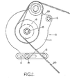
- the drive illustrated therein is for transmitting drive from a crankshaft pulley on an internal combustion engine (not shown) in a motor vehicle to an alternator indicated generally by arrow 10.
- the alternator 10 is provided with a housing 11 which is pivotally mounted on the engine via a support bolt 12 and capable of being clamped in the desired position relative to the engine by means of a mounting bracket 13 having an elongate slot 14 therein and a clamping bolt 15.
- a mounting arrangement for an alternator is known per se and will not be desribed in any further detail except to state that adjustment of the pivotal position of the alternator 10 about the support bolt 12 permits drive belt tensioning.
- the drive comprises a first driven pulley 16 and a second driven pulley 17 which has a larger effective diameter than the first pulley 16.
- the first driven pulley 16 is mounted on a rotary input shaft 18 of the alternator 10 via a bearing 19 so that it is capable of rotating relative to the shaft 18, and is connected with the shaft 18 via a centrifugal clutch device 20 which will be described in more detail hereinafter.
- the second driven pulley 17 is provided on a cup-shaped support member 21 in which the centrifugal clutch device 20 is located.
- the member 21 is connected with the rotary input shaft 18 via a needle roller clutch 22 which is unidirectional so that, when the shaft 18 is driven at a higher speed than the second pulley 17, relative rotation between the second pulley 17 and the shaft 18 can take place, whilst when the second pulley 17 is rotated at a higher speed than the shaft 18 , the second pulley 17 serves to drive the shaft 1$.
- a needle roller clutch 22 is an item which is known per se and will not be described in any further detail.
- the member 21 is rotatable relative to the centrigufal clutch device 20.
- the centrifugal clutch device 20 includes a pair of friction shoes 23 and 24 (see Fig 3-only friction shoe 23 is illustrated in Fig 1).
- the shoes 23 and 24 are identical and each comprises a pair of parallel arcuate plates 25 having an arcuate friction pad 26 secured thereto.
- Each shoe 23, 24 is mounted on the first pulley 16 through the intermediary of a respective pivot pin 27 passing through aligned holes in the plates 25.
- Tension springs 28 are engaged with the respective pivot pins 27 and with respective mounting screws 29.
- the tension springs 23 act in a direction to urge the friction shoes 23 and 24 and the friction pads 26 inwardly by pivoting the shoes 23 and 24 about the respective pivot pins 27.
- Keyed to the rotary input shaft. 18 radially inwardly of the clutch device 20 is a cup-shaped drive plate 30 having an outer peripheral surface engageable by the friction pads 26.
- the drive also includes a further pulley 31 which is mounted on the housing 11 of the alternator so as to be freely rotatable relative thereto but movable towards and away from the axis of the rotary shaft 18 for belt tensioning purposes.
- the housing 11 is provided with an integral boss 3 2 having a radially directed slot 33 the further pulley 31 is mounted for free rotation on a stub shaft 34 via a bearing 35.
- the stub shaft 34 is engaged in the slot 33 and can be clamped in the desired radial position in the slot 33 by means of a nut engaging screw threading 37 on the shaft 34.
- the drive further includes a first drive belt 38 which passes around the first pulley 16, the further pulley 31 and the crankshaft pulley on the internal combustion engine.
- the drive additionally includes a second drive belt 39 which passes around the second pulley 17 and the further pulley 31.
- the first and second belts 38 and 39 run over portions of the further pulley 31 which are of equal effective diameter.
- Tensioning of the first belt 38 can be effected in the usual way by releasing the clamping bolt 15 and pivoting the whole alternator 10 about the axis of support bolt 12.
- Tensioning of the second belt 39 can be effected by releasing the nut 36 and moving the further pulley 31 as permitted by movement of the stub shaft 34 in the slot 33.
- the second drive belt 39 is adjusted to the required tension before the tension of the first belt 38 is adjusted.
- the first belt 38 drives the alternator 10 via the first pulley 16 at a speed which is determined by the ratio of the effective diameters of the crankshaft pulley and the first pulley 16.
- Drive from the first pulley 16 to the alternator 10 is effected via the centrifugal clutch device 20 wherein the friction pads 26 are engaged with the outer peripheral surface of the drive plate 30 under the action of the tension springs 28. 3acause of the engagement of the first belt 38 with the further pulley 31, the latter is also rotated and this causes the second drive belt 39 to rotate the second pulley 17.
- the alternator 10 is driven via the first pulley 16.
- the centrifugal action resulting from rotation of the arcuate plates 25 and associated friction pads 26 causes the former to be pivoted outwardly about the axes of the respective pivot pins 27. This occurs against the action of the tension springs 28.
- the arcuate plates 25 have pivotted outwardly sufficiently far for the drive to the input shaft 18 through the friction pads 26 and the drive plate 30 to be discontinued.
- the alternator 10 continues to be driven by the internal combustion engine but at a lower speed ratio because of the difference in diameter between the first and second pulleys 16 and 17.
- the centrifugal clutch device 20 is arranged so that changeover will occur at an alternator speed of 8660 rpm,the higher speed ratio is 3.3 :1 and the lower speed ratio is 2.2:1.
- the above described drive enables two alternator speed ratios from a single crankshaft pulley. If desired, further variations on the speed ratios can be achieved by arranging for the belts 38 and 39 to run on portions of the further pulley 31 which are at different effective diameters. Thus, if desired, or if necessary, the first and second driven pulleys 16 and 17 could be arranged to have the same effective diameter provided that the belts 38 and 39 run at different effective diameters on the further pulley 31.
- the above described drive may be modified so that the belt which passes around the second pulley 17 also passes around the crankshaft pulley of the internal combustion engine, whilst the belt which passes around the first pulley 16 is arranged to pass only around the further pulley 31.
- the further pulley 31 is dispensed with and the belts 38 and 39 are arranged to pass over a driven pulley of another engine auxiliary, for example a power steering pump or jockey pulley which is adjustably mounted to enable individual belt tensioning.
- a power steering pump or jockey pulley which is adjustably mounted to enable individual belt tensioning.
- Such pump may be positioned to provide the optimum angle of lap for the first belt ,38 around the first pulley 16.
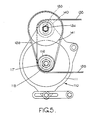
- Figs. 4 and 5 of the drawings the second embodiment illustrated therein operates to provide a two speed ratio drive and parts which are similar to that described with reference to Figs 1 to 3 are accorded the same reference numerals but preceded by the numeral 1.
- first and second driven pulleys 116 and 117 are of substantially the same diameter.
- the first pulley 116 is mounted on rotary input shaft 118 of alternator 110 via unidirectional needle roller clutch 122.
- the second pulley 117 is directly keyed to the shaft 118.
- the drive is provided with first and second further pulleys 140 and 141 which are rotatably mounted on stub shaft 134 via respective bearings 142 and 143.
- the first further pulley 140 has a smaller effective diameter than that of the second further pulley 141 and is provided with centrifugal clutch device 120 including parallel arcuate plates 125, friction pads 126, and pivot pins 127.
- the friction pads 126 act on sleeve 144 which forms part of cup-shaped support member 121 of the second further pulley 141.
- the manner in which centrifugal clutch device operates is the same as that described above with reference to the centrifugal clutch device 20.
- First drive belt 138 passes around the crankshaft pulley (not shown) of the internal combustion engine, around the first driven pulley 116, and around the first further pulley 140.
- Second drive belt 139 passes only around the second driven pulley 117 and the second further pulley 141.
- the first belt 138 drives the alternator 110 via the first further pulley 140, the second further pulley 141, and the second pulley 117. It is to be appreciated that, under these conditions, the friction pads 126 are engaged with the outer surface of sleeve 144 so that drive can be transmitted from the first further pulley 140 to the second further pulley 141. Because of the difference in effective diameters between the pulleys 140 and 141, the shaft 118 is driven at a higher speed than it would be if driven directly by first pulley 116. Under these conditions, rotation of the shaft 118 relative to the first pulley 116 is permitted because of the needle roller clutch 122.
- the centrifugal clutch device 120 operates so that drive is no longer transmitted from the first further pulley 140 to the second further pulley 141. Under these conditions, the rotational speed of the shaft 118 drops until it matches that of the first pulley 116, whereupon the needle roller clutch 122 drivingly connects the first pulley 116 with the input shaft 118.
- the speed of rotation of the shaft 118 below said predetermined engine speed is governed by the ratio of the effective diameter of the crankshaft pulley to the effective diameter of the first further pulley 140, and the ratio of the effective diameter of the second further pulley 141 relative to the respective diameter of the second pulley 117.
- the overall pulley ratio under low engine speed modes of operation can be 4:1 or higher.
- the ratio is 4.44:1, there being a pulley ratio of 2:1 between the crankshaft pulley and the first further pulley 140 and a pulley ratio of 2.22:1 between the second further pulley 141 and the second pulley 117.
- the pulley ratio between the crankshaft pulley and the first pulley 116 can be as little as 2.0:1 so that the alternator is driven relatively slowly at higher engine speeds.
- the changeover from high ratio to low ratio , and vice versa is arranged to occur at an engine speed of about 2800 rpm.
- the centrifugal clutch transmits the torque necessary to accelerate the rotor of the alternator to a higher speed.
- the shock torque as a result of the speed change is transmitted only through the first belt 38
- the torque is transmitted through both the first and second belts 138 and 139 with the result that there is more resilience in the drive to absorb the shock torque.
- the first belt 138 can be of a smaller size than would be necessary to provide a 3:1 ratio for the embodiment of Figs 1 to 3.
- input shaft 218 of alternator 210 has first pulley 216 mounted thereon through the intermediary of needle roller clutch 222, and has second pulley 217 mounted thereon through the intermediary of roller bearing 219.
- the second pulley is operably connected with shaft 218 via centrifugal clutch device 220.
- the first and second pulleys 216 and 217 have the same effective diameter.
- Further pulley 231 comprises pulley portions 240 and 241 over which respective first and second belts 238 and 239 run. Further pulley 231 is freely rotatable relative to stub shaft 234 on bearing 235. The pulley portion 240 over which first belt 238 runs has a smaller effective diameter than that of pulley portion 239 over which the second pulley 239 runs.
- the drives described above with reference to the drawings have the advantage that (1) only a single crankshaft pulley on the engine is required, that (2) no jockey pulleys are required, (3) they are cheaper and easier to manufacture (4) they are quieter in use than an epicyclic pulley arrangement, (5) they require no lubrication even at very high alternator speeds (up to 12000 rpm),(6) they are of relatively low mass, (7) they are easy to fit on the input shaft of the auxiliary and easy and convenient to service. Additionally, since only one crankshaft pulley is required, the modified drive can usually be fitted quite easily to an existing installation. Furthermore, the belt which does not pass around the engine crankshaft pulley need only be short.
- the belts are shown as poly-V belts.
- any other form of belt such as a single V or flat belt, a notched belt or a cog belt or any otherendless flexible drive element may be employed.
Landscapes
- Engineering & Computer Science (AREA)
- General Engineering & Computer Science (AREA)
- Mechanical Engineering (AREA)
- Chemical & Material Sciences (AREA)
- Combustion & Propulsion (AREA)
- Pulleys (AREA)
- Transmissions By Endless Flexible Members (AREA)
- Characterised By The Charging Evacuation (AREA)
Applications Claiming Priority (2)
| Application Number | Priority Date | Filing Date | Title |
|---|---|---|---|
| GB8118782 | 1981-06-18 | ||
| GB8118782 | 1981-06-18 |
Publications (1)
| Publication Number | Publication Date |
|---|---|
| EP0068730A1 true EP0068730A1 (fr) | 1983-01-05 |
Family
ID=10522601
Family Applications (1)
| Application Number | Title | Priority Date | Filing Date |
|---|---|---|---|
| EP82303143A Withdrawn EP0068730A1 (fr) | 1981-06-18 | 1982-06-17 | Entraînement des appareils auxiliaires pour un moteur |
Country Status (4)
| Country | Link |
|---|---|
| EP (1) | EP0068730A1 (fr) |
| JP (1) | JPS5813128A (fr) |
| AU (1) | AU8496882A (fr) |
| ZA (1) | ZA824205B (fr) |
Cited By (16)
| Publication number | Priority date | Publication date | Assignee | Title |
|---|---|---|---|---|
| EP0154785A1 (fr) * | 1984-02-01 | 1985-09-18 | RIV-SKF OFFICINE DI VILLAR PEROSA S.p.A | Unité de transmission par courroie pour le transfert de l'entraînement entre l'arbre d'entraînement d'un moteur à combustion interne et des accessoires auxiliaires |
| DE4309548A1 (de) * | 1993-03-24 | 1994-09-29 | Schaeffler Waelzlager Kg | Antrieb von mindestens einem Zusatzaggregat einer Brennkraftmaschine |
| DE19535889A1 (de) * | 1995-09-27 | 1997-04-03 | Schaeffler Waelzlager Kg | Freilaufkupplung für einen Lichtmaschinenantrieb |
| WO2004054071A3 (fr) * | 2002-12-06 | 2004-09-10 | Renault Sa | Entretoise de galet enrouleur pour alternateur de moteur d'automobile |
| WO2004101973A1 (fr) * | 2003-05-17 | 2004-11-25 | Ina-Schaeffler Kg | Dispositif pour des equipements auxiliaires d'un moteur a combustion interne |
| EP1544435A1 (fr) * | 2003-12-18 | 2005-06-22 | INA-Schaeffler KG | Dispositif de transmission de puissance, notamment pour véhicules |
| WO2014153032A1 (fr) | 2013-03-14 | 2014-09-25 | Evolutionary Genomics, Inc. | Identification et utilisation de gènes de la tomate contrôlant la tolérance au sel/à la sécheresse et le goût sucré du fruit |
| EP2927323A2 (fr) | 2011-04-11 | 2015-10-07 | Targeted Growth, Inc. | Identification et utilisation de mutants kpr dans des plantes |
| DE102015211867A1 (de) * | 2015-06-25 | 2016-12-29 | Volkswagen Aktiengesellschaft | Anordnung eines drehbar gelagerten Elements an einem Gehäuse |
| EP3552482A1 (fr) | 2013-10-29 | 2019-10-16 | Biotech Institute, LLC | Sélection, production, traitement et utilisation de cannabis spécial |
| US11530419B2 (en) | 2020-10-30 | 2022-12-20 | Fortiphyte, Inc. | Pathogen resistance in plants |
| WO2024052856A1 (fr) | 2022-09-09 | 2024-03-14 | Friedrich Alexander Universität Erlangen-Nürnberg | Éléments régulateurs chez des plantes et leurs utilisations |
| WO2025030048A2 (fr) | 2023-08-03 | 2025-02-06 | J.R. Simplot Company | Gènes de résistance aux fusarioses |
| US12225874B2 (en) | 2023-03-27 | 2025-02-18 | Redsea Science And Technology Inc. | Tomato plant designated ‘X22-31’ |
| WO2025046294A1 (fr) | 2023-08-29 | 2025-03-06 | University Of Freiburg | Protéines pour la régulation d'une infection symbiotique et éléments régulateurs associés |
| WO2025259554A1 (fr) | 2024-06-13 | 2025-12-18 | J.R. Simplot Company | Ingénierie de la floraison remontante chez des rosaceae |
Families Citing this family (3)
| Publication number | Priority date | Publication date | Assignee | Title |
|---|---|---|---|---|
| JPH0413387Y2 (fr) * | 1985-02-19 | 1992-03-27 | ||
| US4695261A (en) * | 1985-07-03 | 1987-09-22 | Outboard Marine Corporation | Marine propulsion engine voltage generator arrangement |
| US7435441B2 (en) | 2002-01-23 | 2008-10-14 | Adeka Corporation | Fat composition |
Citations (6)
| Publication number | Priority date | Publication date | Assignee | Title |
|---|---|---|---|---|
| US3436977A (en) * | 1968-01-02 | 1969-04-08 | Marcellus W Gredell | Two-speed automatic transmission |
| DE2055404A1 (de) * | 1970-11-11 | 1972-05-18 | Daimler-Benz Ag, 7000 Stuttgart | Antrieb des Kühlluftgebläses einer Brennkraftmaschine |
| FR2201739A5 (fr) * | 1972-10-02 | 1974-04-26 | Fmc Corp | |
| FR2378948A1 (fr) * | 1977-01-26 | 1978-08-25 | Bosch Gmbh Robert | Entrainement pour les appareils auxiliaires d'un moteur a combustion interne, en particulier a bord d'un vehicule automobile |
| DE2952249A1 (de) * | 1979-12-24 | 1981-07-02 | Fabbrica Italiana Magneti Marelli S.p.A., Milano | Vorrichtung zur kraftuebertragung vom verbrennungsmotor eines fahrzeugs auf eine diesem zugeordnete hilfsmaschine |
| FR2486610A1 (fr) * | 1980-07-11 | 1982-01-15 | Paris & Du Rhone | Dispositif d'entrainement rotatif a deux vitesses, notamment pour alternateur de vehicule automobile |
-
1982
- 1982-06-15 ZA ZA824205A patent/ZA824205B/xx unknown
- 1982-06-17 EP EP82303143A patent/EP0068730A1/fr not_active Withdrawn
- 1982-06-18 AU AU84968/82A patent/AU8496882A/en not_active Abandoned
- 1982-06-18 JP JP57104065A patent/JPS5813128A/ja active Pending
Patent Citations (6)
| Publication number | Priority date | Publication date | Assignee | Title |
|---|---|---|---|---|
| US3436977A (en) * | 1968-01-02 | 1969-04-08 | Marcellus W Gredell | Two-speed automatic transmission |
| DE2055404A1 (de) * | 1970-11-11 | 1972-05-18 | Daimler-Benz Ag, 7000 Stuttgart | Antrieb des Kühlluftgebläses einer Brennkraftmaschine |
| FR2201739A5 (fr) * | 1972-10-02 | 1974-04-26 | Fmc Corp | |
| FR2378948A1 (fr) * | 1977-01-26 | 1978-08-25 | Bosch Gmbh Robert | Entrainement pour les appareils auxiliaires d'un moteur a combustion interne, en particulier a bord d'un vehicule automobile |
| DE2952249A1 (de) * | 1979-12-24 | 1981-07-02 | Fabbrica Italiana Magneti Marelli S.p.A., Milano | Vorrichtung zur kraftuebertragung vom verbrennungsmotor eines fahrzeugs auf eine diesem zugeordnete hilfsmaschine |
| FR2486610A1 (fr) * | 1980-07-11 | 1982-01-15 | Paris & Du Rhone | Dispositif d'entrainement rotatif a deux vitesses, notamment pour alternateur de vehicule automobile |
Cited By (19)
| Publication number | Priority date | Publication date | Assignee | Title |
|---|---|---|---|---|
| EP0154785A1 (fr) * | 1984-02-01 | 1985-09-18 | RIV-SKF OFFICINE DI VILLAR PEROSA S.p.A | Unité de transmission par courroie pour le transfert de l'entraînement entre l'arbre d'entraînement d'un moteur à combustion interne et des accessoires auxiliaires |
| DE4309548A1 (de) * | 1993-03-24 | 1994-09-29 | Schaeffler Waelzlager Kg | Antrieb von mindestens einem Zusatzaggregat einer Brennkraftmaschine |
| DE19535889A1 (de) * | 1995-09-27 | 1997-04-03 | Schaeffler Waelzlager Kg | Freilaufkupplung für einen Lichtmaschinenantrieb |
| WO2004054071A3 (fr) * | 2002-12-06 | 2004-09-10 | Renault Sa | Entretoise de galet enrouleur pour alternateur de moteur d'automobile |
| WO2004101973A1 (fr) * | 2003-05-17 | 2004-11-25 | Ina-Schaeffler Kg | Dispositif pour des equipements auxiliaires d'un moteur a combustion interne |
| US7347309B2 (en) | 2003-05-17 | 2008-03-25 | Ina-Schaeffler Kg | Device for auxiliary units of an internal combustion engine |
| EP1544435A1 (fr) * | 2003-12-18 | 2005-06-22 | INA-Schaeffler KG | Dispositif de transmission de puissance, notamment pour véhicules |
| EP2927323A2 (fr) | 2011-04-11 | 2015-10-07 | Targeted Growth, Inc. | Identification et utilisation de mutants kpr dans des plantes |
| WO2014153032A1 (fr) | 2013-03-14 | 2014-09-25 | Evolutionary Genomics, Inc. | Identification et utilisation de gènes de la tomate contrôlant la tolérance au sel/à la sécheresse et le goût sucré du fruit |
| EP3552482A1 (fr) | 2013-10-29 | 2019-10-16 | Biotech Institute, LLC | Sélection, production, traitement et utilisation de cannabis spécial |
| DE102015211867A1 (de) * | 2015-06-25 | 2016-12-29 | Volkswagen Aktiengesellschaft | Anordnung eines drehbar gelagerten Elements an einem Gehäuse |
| US11530419B2 (en) | 2020-10-30 | 2022-12-20 | Fortiphyte, Inc. | Pathogen resistance in plants |
| WO2024052856A1 (fr) | 2022-09-09 | 2024-03-14 | Friedrich Alexander Universität Erlangen-Nürnberg | Éléments régulateurs chez des plantes et leurs utilisations |
| US12225874B2 (en) | 2023-03-27 | 2025-02-18 | Redsea Science And Technology Inc. | Tomato plant designated ‘X22-31’ |
| US12239091B2 (en) | 2023-03-27 | 2025-03-04 | Redsea Science And Technology Inc. | Tomato plant designated ‘MX20-06’ |
| US12419265B2 (en) | 2023-03-27 | 2025-09-23 | Redsea Science And Technology Inc. | Tomato plant designated ‘X21-02’ |
| WO2025030048A2 (fr) | 2023-08-03 | 2025-02-06 | J.R. Simplot Company | Gènes de résistance aux fusarioses |
| WO2025046294A1 (fr) | 2023-08-29 | 2025-03-06 | University Of Freiburg | Protéines pour la régulation d'une infection symbiotique et éléments régulateurs associés |
| WO2025259554A1 (fr) | 2024-06-13 | 2025-12-18 | J.R. Simplot Company | Ingénierie de la floraison remontante chez des rosaceae |
Also Published As
| Publication number | Publication date |
|---|---|
| ZA824205B (en) | 1983-04-27 |
| AU8496882A (en) | 1982-12-23 |
| JPS5813128A (ja) | 1983-01-25 |
Similar Documents
| Publication | Publication Date | Title |
|---|---|---|
| US4698049A (en) | Belt tensioner with frustoconical pivot bearing | |
| US3924483A (en) | Belt driven accessory for vehicles with automatic belt tensioner | |
| JP2761191B2 (ja) | ベルト伝動方法及びベルト伝動装置 | |
| KR100783455B1 (ko) | 이중 속도비의 벨트 구동 시스템 | |
| RU2405952C2 (ru) | Система ременной передачи с изменяемым передаточным отношением | |
| US8568259B2 (en) | Engine accessory drive with belt tensioner and same plane idler | |
| CA3082420C (fr) | Tendeur rotatif | |
| CN110177926B (zh) | 具有多比率和扭矩反向的附件带驱动系统 | |
| KR20200045547A (ko) | 텐셔너 및 방법 | |
| US4296852A (en) | Automatic two-way centrifugal clutch for motor driven apparatus | |
| KR930000311A (ko) | 코일 스프링 단방향의 클러치 교류기 연결을 가지는 서어펀타인(serpentine) 구동장치 | |
| US2911962A (en) | Engine accessory drive | |
| US3747731A (en) | Constant speed centrifugal clutch | |
| JPH08246893A (ja) | エンジン用補機のベルト伝動装置 | |
| JPS5813128A (ja) | 機関補機駆動装置 | |
| US1782513A (en) | Internal-combustion engine | |
| JP4315362B2 (ja) | ベルト伝動装置 | |
| US4517482A (en) | Vehicular-type alternator with speed-responsive fan coupling | |
| EP0012815B1 (fr) | Embrayage dépendant de l'accélération | |
| US5058546A (en) | Engine air pump with speed drum drive | |
| IE970277A1 (en) | Centrifugal Clutch | |
| JPH05332156A (ja) | 補機駆動装置 | |
| JP2979014B2 (ja) | 自動二輪車のvベルト自動変速機 | |
| US2945482A (en) | Variable speed drives | |
| US3296892A (en) | Constant select speed accessory group drive |
Legal Events
| Date | Code | Title | Description |
|---|---|---|---|
| PUAI | Public reference made under article 153(3) epc to a published international application that has entered the european phase |
Free format text: ORIGINAL CODE: 0009012 |
|
| AK | Designated contracting states |
Designated state(s): DE FR GB IT |
|
| STAA | Information on the status of an ep patent application or granted ep patent |
Free format text: STATUS: THE APPLICATION IS DEEMED TO BE WITHDRAWN |
|
| 18D | Application deemed to be withdrawn |
Effective date: 19831212 |
|
| RIN1 | Information on inventor provided before grant (corrected) |
Inventor name: HEMMINGS, ROBERT Inventor name: CROSS, DENNIS ROWLAND |