EP0068734A2 - Mehrstufentrockner für körniges Material mit kanalisierter Abführung - Google Patents
Mehrstufentrockner für körniges Material mit kanalisierter Abführung Download PDFInfo
- Publication number
- EP0068734A2 EP0068734A2 EP82303149A EP82303149A EP0068734A2 EP 0068734 A2 EP0068734 A2 EP 0068734A2 EP 82303149 A EP82303149 A EP 82303149A EP 82303149 A EP82303149 A EP 82303149A EP 0068734 A2 EP0068734 A2 EP 0068734A2
- Authority
- EP
- European Patent Office
- Prior art keywords
- drying
- column
- particulate material
- dryer
- columns
- Prior art date
- Legal status (The legal status is an assumption and is not a legal conclusion. Google has not performed a legal analysis and makes no representation as to the accuracy of the status listed.)
- Granted
Links
Images


Classifications
-
- F—MECHANICAL ENGINEERING; LIGHTING; HEATING; WEAPONS; BLASTING
- F26—DRYING
- F26B—DRYING SOLID MATERIALS OR OBJECTS BY REMOVING LIQUID THEREFROM
- F26B17/00—Machines or apparatus for drying materials in loose, plastic, or fluidised form, e.g. granules, staple fibres, with progressive movement
- F26B17/12—Machines or apparatus for drying materials in loose, plastic, or fluidised form, e.g. granules, staple fibres, with progressive movement with movement performed solely by gravity, i.e. the material moving through a substantially vertical drying enclosure, e.g. shaft
- F26B17/122—Machines or apparatus for drying materials in loose, plastic, or fluidised form, e.g. granules, staple fibres, with progressive movement with movement performed solely by gravity, i.e. the material moving through a substantially vertical drying enclosure, e.g. shaft the material moving through a cross-flow of drying gas; the drying enclosure, e.g. shaft, consisting of substantially vertical, perforated walls
-
- F—MECHANICAL ENGINEERING; LIGHTING; HEATING; WEAPONS; BLASTING
- F26—DRYING
- F26B—DRYING SOLID MATERIALS OR OBJECTS BY REMOVING LIQUID THEREFROM
- F26B25/00—Details of general application not covered by group F26B21/00 or F26B23/00
- F26B25/001—Handling, e.g. loading or unloading arrangements
- F26B25/002—Handling, e.g. loading or unloading arrangements for bulk goods
Definitions
- the present invention provides a gravity flow grain dryer for particulate material comprising a first generally vertical drying column having first and second opposed spaced perforate walls.
- a second generally vertical drying column having first and_second opposed spaced perforate walls is also provided, the first and second drying columns being spaced apart to provide a plenum chamber between the columns, the first perforate walls of each drying column defining the side walls of the plenum chamber.
- First and second input means are provided for introducing particulate material into the first and second drying columns, respectively.
- First and second discharge means are provided for removing particulate material from the first and second drying cclumns, respectively.
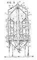
- a column type gravity flow dryer for particulate material for example, corn or other type grain.
- the dryer generally designated 10, includes a generally square-shaped housing 12 comprised of a pair of solid end walls 14 and 16 and a pair of side walls 18 and 20. Each of the side walls 18 and 20 includes solid upper and lower portions 22 and 24, respectively, and a perforate intermedite portion 26.
- the housing 12 further includes a suitable roof 28 and is supported at the bottom by suitable support means or legs 30.
- At the top of the housing 12 is a means for introducing moist particulate material or grain into the top portion of the housing, in this embodiment, a suitably sized wet grain inlet 32.
- the heater section 40 and the blower section 38 are separated by a generally horizontally disposed partition 64 which contains an airflow control means, comprising in this embodiment, a plurality of adjustable dampers 66.
- the adjustable dampers 66 are provided to control the flow of air from the hot air fan 44 to the burner 58.- In this manner, it is possible to effectively regulate the hot air flow into the housing 12 to efficiently dry a variety of different types of particulate material. For example, it may be desirable to provide a large hot ⁇ ir flow into the housing 12 for drying high moisture content corn and a much smaller hot air flow into the housing 12 for drying lower moisture content rice.
- the adjustable dampers 66 may be set in a substantially fully open position to apply a large hot air flow to dry corn or in a substantially closed position to apply a small hot air flow when drying rice.
- each of the outer drying columns 68 is a dividing wall means, in the present embodiment a generally vertical partition 76, for dividing the lower portion of each of the drying columns 68 into two generally parallel channels 78 and 80.
- Each of the channels 78 and 80 preferably contains separate discharge means, in the present embodiment metering rolls 82 and 84, respectively, for discharging particulate material from the channels 78 and 80 at predetermined rates.
- Both of the metering rolls 82 and 84 are driven by a system of drive belts and pulleys generally designated 85. As shown, the drive pulley for the metering roll 84 is of a smaller diameter than the drive pulley for metering roll 82.
- metering roll 84 rotates faster than metering roll 82 to thereby discharge grain from the innermost channel 80 at a faster rate than the grain is discharged from the outermost channel 78.
- the grain from both channels 78 and 80 is discharged by the respective metering rolls 82 and 84 into a receiving hopper 86.
- the inner drying columns 100 also have a generally vertical partition 118, which divides each column into inner and outer channels 120 and 122 in a manner corresponding to the partitions 76 for the outer drying columns 68.
- Discharge means in the form of metering rolls 124 and 126 are also provided for discharging grain from the inner and outer channels 120 and 122, respectively.
- the metering rolls 124 and 126 also turn at different predetermined rates for discharging the grain from the channels 120 and 122 at different rates.
- the metering rolls 126 adjacent the first perforate walls 108 discharge the material at a rate faster than the metering rolls 124.
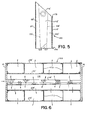
- a pair of complementary modules 160 When a pair of complementary modules 160 are placed in position in the dryer housing 12 as shown in Fig. 4, they form the drying columns 68 and 100.
- the upper and lower portions of the modules 160 are suitably contoured to enable the modules to be appropriately positioned within the dryer housing 12 as shown in Fig. 4.
- the tapered perforate tubes 116 are connected to and cooperate with the hot air ducts 62 (shown in Fig. 1) for the distribution of hot air within the plenum chamber 112.
- the triangular-shaped air ducts 127 are connected to and cooperate with the cooling air ducts 56 (shown in Fig. 1) to provide a flow of cooling air when the modules 160 are in place within the dryer housing 12.
- the grain flowing down the columns adjacent to perforate walls 70 is dried more rapidly than the grain flowing down the column adjacent outer walls 26. Accordingly, as also discussed in detail above relative to Fig. 3, the grain flowing through the columns 68 adjacent perforate walls 70 is discharged from the columns 68 at a faster rate than the grain flowing down the column adjacent the perforate walls 26.
- All of the grain discharged from the outer columns 68 is received and collected in the first receiving hopper 86.
- the collected grain flows downwardly within the hopper 86 and enters the vertical tube member 88 through the openings 94.
- the rotating grain auger 90 within the vertical tube member 88 transports the grain upwardly to the top of the tube member 88 where it is discharged into the steeping chamber 96.
- the heated air passing through the inner drying columns 100 enters the central chamber 134 and is recycled back to the hot air fan 44 for reuse.
- the cooling air which has passed through the inner columns 100 and has picked up heat from the heated grain within the columns is recycled back to the hot air fan 44 in the same manner.
- the heated air passing through the outer columns 68 is too saturated with moisture which has been removed from the grain, to be of desired use in recycling, and, thus, is exhausted to the atmosphere through the outer perforate walls 26.
- the tubular structure 210 may be removed from the base portion 202 and turned over or reversed to a position as shown in Fig. 13, with the second (perforated wall) chamber 222 adjacent the base portion 2.02, and with the first (solid wall) chamber 220 being remote from the base portion 202.
- the reversal of the tubular structure 210 is accomplished by simply removing the nuts and bolts 212 from the flanges 214 and 216, reversing end-for-end the tubular structure 210, and replacing the nuts and bolts 212 through the corresponding aligned flanges 214 and 216'.
- the chamber adjacent the base portion 202 serves as a heat exchange chamber, while the chamber remote from the base portion 202 functions as a manifold chamber.
- the combustion gases pass upwardly and are exhausted to the atmosphere as shown between covering member 229, which is supported by projections 241, and flange 216.
- Ambient air is drawn into the apparatus through the air inlet means 223 (now located in the heat exchange chamber) as shown in Fig. 13,'passes around the hot vertical tubes 208 and is heated thereby. The heated ambient air is then drawn into the dryer 10 through the opening 234.
Landscapes
- Engineering & Computer Science (AREA)
- Mechanical Engineering (AREA)
- General Engineering & Computer Science (AREA)
- Drying Of Solid Materials (AREA)
Priority Applications (1)
| Application Number | Priority Date | Filing Date | Title |
|---|---|---|---|
| AT82303149T ATE33306T1 (de) | 1981-06-19 | 1982-06-17 | Mehrstufentrockner fuer koerniges material mit kanalisierter abfuehrung. |
Applications Claiming Priority (4)
| Application Number | Priority Date | Filing Date | Title |
|---|---|---|---|
| US06/275,313 US4398356A (en) | 1981-06-19 | 1981-06-19 | Multi-stage dryer for particulate material |
| US275312 | 1981-06-19 | ||
| US06/275,312 US4423557A (en) | 1981-06-19 | 1981-06-19 | Gravity flow dryer for particulate material having channelized discharge |
| US275313 | 1988-11-23 |
Related Child Applications (2)
| Application Number | Title | Priority Date | Filing Date |
|---|---|---|---|
| EP86107817A Division EP0206069A3 (de) | 1981-06-19 | 1982-06-17 | Mehrstufentrockner für körniges Material mit kanalisierter Entleerung |
| EP86107817.8 Division-Into | 1982-06-17 |
Publications (3)
| Publication Number | Publication Date |
|---|---|
| EP0068734A2 true EP0068734A2 (de) | 1983-01-05 |
| EP0068734A3 EP0068734A3 (en) | 1984-09-12 |
| EP0068734B1 EP0068734B1 (de) | 1988-03-30 |
Family
ID=26957361
Family Applications (2)
| Application Number | Title | Priority Date | Filing Date |
|---|---|---|---|
| EP86107817A Ceased EP0206069A3 (de) | 1981-06-19 | 1982-06-17 | Mehrstufentrockner für körniges Material mit kanalisierter Entleerung |
| EP19820303149 Expired EP0068734B1 (de) | 1981-06-19 | 1982-06-17 | Mehrstufentrockner für körniges Material mit kanalisierter Abführung |
Family Applications Before (1)
| Application Number | Title | Priority Date | Filing Date |
|---|---|---|---|
| EP86107817A Ceased EP0206069A3 (de) | 1981-06-19 | 1982-06-17 | Mehrstufentrockner für körniges Material mit kanalisierter Entleerung |
Country Status (10)
| Country | Link |
|---|---|
| EP (2) | EP0206069A3 (de) |
| AR (1) | AR226984A1 (de) |
| AU (2) | AU565672B2 (de) |
| BR (1) | BR8203554A (de) |
| CA (1) | CA1176053A (de) |
| DE (1) | DE3278292D1 (de) |
| DK (2) | DK259682A (de) |
| GR (1) | GR76498B (de) |
| HU (1) | HU189147B (de) |
| NZ (1) | NZ200681A (de) |
Cited By (6)
| Publication number | Priority date | Publication date | Assignee | Title |
|---|---|---|---|---|
| AU582301B2 (en) * | 1981-06-19 | 1989-03-16 | Christianus M.T. Westelaken | Multi-stage particulate material dryer having channelized discharge |
| GB2338286A (en) * | 1998-06-12 | 1999-12-15 | Sukup Mfg | Drying grain |
| WO2005028977A1 (en) * | 2003-09-25 | 2005-03-31 | Maddingley Coldry Pty Ltd | Dryer, drying method and drying plant |
| CN106679393A (zh) * | 2017-01-20 | 2017-05-17 | 中国科学院理化技术研究所 | 一种粮食烘干系统 |
| CN109095017A (zh) * | 2018-09-06 | 2018-12-28 | 云南中烟工业有限责任公司 | 一种新型打叶器进料流量控制装置 |
| CN113280610A (zh) * | 2021-05-31 | 2021-08-20 | 安徽华谷机械科技有限公司 | 一种梯度脱水的粮食烘干机 |
Families Citing this family (2)
| Publication number | Priority date | Publication date | Assignee | Title |
|---|---|---|---|---|
| GB201007697D0 (en) | 2010-05-06 | 2010-06-23 | Ucl Business Plc | A supra-threshold test for use in detecting sensitivity loss across the field of vision |
| CN114963740B (zh) * | 2022-04-29 | 2023-07-07 | 江苏经贸职业技术学院 | 一种食品加工烘干装置 |
Family Cites Families (14)
| Publication number | Priority date | Publication date | Assignee | Title |
|---|---|---|---|---|
| US2732630A (en) * | 1956-01-31 | Markowich | ||
| GB190920758A (en) * | 1909-09-10 | 1910-09-12 | Diedrich Uhlhorn | Shaft Drier for Corn with Automatically Regulated Discharge of the Dried Material. |
| GB213799A (en) * | 1923-05-25 | 1924-04-10 | George Richard Schueler | Improvements in apparatus for cooling and drying nuts, cubes and similarly shaped pieces of compressed material for use as food for cattle and other animals, and grain, seed and other material in bulk |
| DE462031C (de) * | 1925-11-07 | 1928-07-03 | Otto Nordstroem | Schachttrockner mit einem aus Siebmaenteln gebildeten Ringschacht |
| DE717052C (de) * | 1939-01-12 | 1942-02-04 | August Gronert | Rieselschachttrockner fuer koerniges Gut |
| US3078590A (en) * | 1960-06-27 | 1963-02-26 | A F Meyer Mfg Co | Grain dryer |
| US3238640A (en) * | 1962-09-04 | 1966-03-08 | Hart Carter Co | Grain dryer |
| DE1604920B2 (de) * | 1965-12-23 | 1973-01-18 | Wilhelm Heine, Malzfabrik, 3150 Peine | Vertikaltrockner fuer getreide bzw. zum schwelken und darren von malz |
| FR93262E (fr) * | 1966-08-31 | 1969-03-07 | Etablissements Rivierre Casali | Séchoir pour produits granuleux. |
| US3426442A (en) * | 1967-06-01 | 1969-02-11 | Toshihiko Satake | Drying apparatus for cereals |
| CH497768A (de) * | 1968-10-10 | 1970-10-15 | Sulzer Ag | Bestrahlungsanlage, insbesondere für körniges Gut |
| US4223452A (en) * | 1979-02-12 | 1980-09-23 | Chambers John M | Drying process and apparatus for accomplishing the same |
| US4423557A (en) * | 1981-06-19 | 1984-01-03 | Westelaken C | Gravity flow dryer for particulate material having channelized discharge |
| NZ200681A (en) * | 1981-06-19 | 1987-03-06 | Westelaken C | Gravity flow grain dryer with two stages of drying |
-
1982
- 1982-05-19 NZ NZ20068182A patent/NZ200681A/en unknown
- 1982-06-09 AU AU84702/82A patent/AU565672B2/en not_active Ceased
- 1982-06-10 DK DK259682A patent/DK259682A/da not_active Application Discontinuation
- 1982-06-11 GR GR68412A patent/GR76498B/el unknown
- 1982-06-17 EP EP86107817A patent/EP0206069A3/de not_active Ceased
- 1982-06-17 DE DE8282303149T patent/DE3278292D1/de not_active Expired
- 1982-06-17 EP EP19820303149 patent/EP0068734B1/de not_active Expired
- 1982-06-17 BR BR8203554A patent/BR8203554A/pt unknown
- 1982-06-17 AR AR28970582A patent/AR226984A1/es active
- 1982-06-18 HU HU200182A patent/HU189147B/hu not_active IP Right Cessation
- 1982-06-18 CA CA000405450A patent/CA1176053A/en not_active Expired
-
1987
- 1987-03-24 AU AU70551/87A patent/AU582301B2/en not_active Ceased
-
1988
- 1988-08-19 DK DK468988A patent/DK468988A/da not_active Application Discontinuation
Cited By (10)
| Publication number | Priority date | Publication date | Assignee | Title |
|---|---|---|---|---|
| AU582301B2 (en) * | 1981-06-19 | 1989-03-16 | Christianus M.T. Westelaken | Multi-stage particulate material dryer having channelized discharge |
| GB2338286A (en) * | 1998-06-12 | 1999-12-15 | Sukup Mfg | Drying grain |
| GB2338286B (en) * | 1998-06-12 | 2001-11-14 | Sukup Mfg | Method and apparatus for drying grain |
| WO2005028977A1 (en) * | 2003-09-25 | 2005-03-31 | Maddingley Coldry Pty Ltd | Dryer, drying method and drying plant |
| AU2004274520B2 (en) * | 2003-09-25 | 2009-07-23 | Ect Coldry Pty Ltd | Dryer, drying method and drying plant |
| AU2010100952B4 (en) * | 2003-09-25 | 2010-10-28 | Ect Coldry Pty Ltd | Dryer and drying plant |
| AU2004274520C1 (en) * | 2003-09-25 | 2010-12-09 | Ect Coldry Pty Ltd | Dryer, drying method and drying plant |
| CN106679393A (zh) * | 2017-01-20 | 2017-05-17 | 中国科学院理化技术研究所 | 一种粮食烘干系统 |
| CN109095017A (zh) * | 2018-09-06 | 2018-12-28 | 云南中烟工业有限责任公司 | 一种新型打叶器进料流量控制装置 |
| CN113280610A (zh) * | 2021-05-31 | 2021-08-20 | 安徽华谷机械科技有限公司 | 一种梯度脱水的粮食烘干机 |
Also Published As
| Publication number | Publication date |
|---|---|
| HUT35834A (en) | 1985-07-29 |
| AU582301B2 (en) | 1989-03-16 |
| EP0068734A3 (en) | 1984-09-12 |
| EP0206069A3 (de) | 1987-02-25 |
| DK468988D0 (da) | 1988-08-19 |
| DK468988A (da) | 1988-08-19 |
| DK259682A (da) | 1982-12-20 |
| EP0206069A2 (de) | 1986-12-30 |
| EP0068734B1 (de) | 1988-03-30 |
| AU8470282A (en) | 1982-12-23 |
| GR76498B (de) | 1984-08-10 |
| DE3278292D1 (en) | 1988-05-05 |
| BR8203554A (pt) | 1983-06-07 |
| AU565672B2 (en) | 1987-09-24 |
| AU7055187A (en) | 1987-07-09 |
| NZ200681A (en) | 1987-03-06 |
| AR226984A1 (es) | 1982-08-31 |
| HU189147B (en) | 1986-06-30 |
| CA1176053A (en) | 1984-10-16 |
Similar Documents
| Publication | Publication Date | Title |
|---|---|---|
| US4424634A (en) | Modular column dryer for particulate material | |
| US4423557A (en) | Gravity flow dryer for particulate material having channelized discharge | |
| US4125945A (en) | Multiple stage grain dryer with intermediate steeping | |
| US4398356A (en) | Multi-stage dryer for particulate material | |
| CA2868285C (en) | Multiple product belt drier for drying pasty and/or powdery materials, particularly for sludges from treatment plants or biomass | |
| US5195251A (en) | Drying kiln | |
| US4477984A (en) | Multi purpose three pass drum dryer | |
| US3629954A (en) | Gravity flow grain dries | |
| JPS5833470B2 (ja) | レンゾクセンタクドライヤ− | |
| US4402302A (en) | Air heating apparatus | |
| US4152841A (en) | Flow control meters for gravity flow particle dryers | |
| CN113203251B (zh) | 一种谷物流化床干燥装置 | |
| CA1176053A (en) | Multi-stage particulate material dryer | |
| KR101823598B1 (ko) | 용량 가변형 열회수 건조기 | |
| US5443539A (en) | Particulate dryer | |
| US6601317B2 (en) | High-efficiency drying kiln particularly for wood-like material | |
| GB2338286A (en) | Drying grain | |
| CA1195108A (en) | Multi-stage particulate material dryer having channelized discharge | |
| NZ213520A (en) | Gravity flow grain dryer:differential flow rates | |
| RU2082924C1 (ru) | Циклическая сушилка для сыпучих материалов | |
| KR0135062B1 (ko) | 열풍건조방법 및 그 장치 | |
| US3604126A (en) | Grain treatment apparatus | |
| RU2099655C1 (ru) | Способ сушки зерна и аэродинамическая сушилка | |
| KR20000040206A (ko) | 곡물 및 고추 건조장치 | |
| RU2067270C1 (ru) | Ромбическая сушилка |
Legal Events
| Date | Code | Title | Description |
|---|---|---|---|
| PUAI | Public reference made under article 153(3) epc to a published international application that has entered the european phase |
Free format text: ORIGINAL CODE: 0009012 |
|
| AK | Designated contracting states |
Designated state(s): AT BE CH DE FR GB IT LI NL SE |
|
| PUAL | Search report despatched |
Free format text: ORIGINAL CODE: 0009013 |
|
| AK | Designated contracting states |
Designated state(s): AT BE CH DE FR GB IT LI NL SE |
|
| 17P | Request for examination filed |
Effective date: 19850302 |
|
| GRAA | (expected) grant |
Free format text: ORIGINAL CODE: 0009210 |
|
| AK | Designated contracting states |
Kind code of ref document: B1 Designated state(s): AT BE CH DE FR GB IT LI NL SE |
|
| REF | Corresponds to: |
Ref document number: 33306 Country of ref document: AT Date of ref document: 19880415 Kind code of ref document: T |
|
| REF | Corresponds to: |
Ref document number: 3278292 Country of ref document: DE Date of ref document: 19880505 |
|
| ITF | It: translation for a ep patent filed | ||
| ET | Fr: translation filed | ||
| PLBE | No opposition filed within time limit |
Free format text: ORIGINAL CODE: 0009261 |
|
| STAA | Information on the status of an ep patent application or granted ep patent |
Free format text: STATUS: NO OPPOSITION FILED WITHIN TIME LIMIT |
|
| 26N | No opposition filed | ||
| PGFP | Annual fee paid to national office [announced via postgrant information from national office to epo] |
Ref country code: SE Payment date: 19890607 Year of fee payment: 8 |
|
| PGFP | Annual fee paid to national office [announced via postgrant information from national office to epo] |
Ref country code: CH Payment date: 19890609 Year of fee payment: 8 |
|
| PGFP | Annual fee paid to national office [announced via postgrant information from national office to epo] |
Ref country code: AT Payment date: 19890612 Year of fee payment: 8 |
|
| ITTA | It: last paid annual fee | ||
| PGFP | Annual fee paid to national office [announced via postgrant information from national office to epo] |
Ref country code: NL Payment date: 19890630 Year of fee payment: 8 Ref country code: GB Payment date: 19890630 Year of fee payment: 8 Ref country code: FR Payment date: 19890630 Year of fee payment: 8 |
|
| PGFP | Annual fee paid to national office [announced via postgrant information from national office to epo] |
Ref country code: BE Payment date: 19890809 Year of fee payment: 8 |
|
| PGFP | Annual fee paid to national office [announced via postgrant information from national office to epo] |
Ref country code: DE Payment date: 19890829 Year of fee payment: 8 |
|
| PG25 | Lapsed in a contracting state [announced via postgrant information from national office to epo] |
Ref country code: GB Effective date: 19900617 Ref country code: AT Effective date: 19900617 |
|
| PG25 | Lapsed in a contracting state [announced via postgrant information from national office to epo] |
Ref country code: SE Effective date: 19900618 |
|
| PG25 | Lapsed in a contracting state [announced via postgrant information from national office to epo] |
Ref country code: LI Effective date: 19900630 Ref country code: CH Effective date: 19900630 Ref country code: BE Effective date: 19900630 |
|
| BERE | Be: lapsed |
Owner name: WESTELAKEN CHRISTIANUS MARINUS THERESIA Effective date: 19900630 |
|
| PG25 | Lapsed in a contracting state [announced via postgrant information from national office to epo] |
Ref country code: NL Effective date: 19910101 |
|
| GBPC | Gb: european patent ceased through non-payment of renewal fee | ||
| NLV4 | Nl: lapsed or anulled due to non-payment of the annual fee | ||
| PG25 | Lapsed in a contracting state [announced via postgrant information from national office to epo] |
Ref country code: FR Effective date: 19910228 |
|
| REG | Reference to a national code |
Ref country code: CH Ref legal event code: PL |
|
| PG25 | Lapsed in a contracting state [announced via postgrant information from national office to epo] |
Ref country code: DE Effective date: 19910301 |
|
| REG | Reference to a national code |
Ref country code: FR Ref legal event code: ST |
|
| EUG | Se: european patent has lapsed |
Ref document number: 82303149.7 Effective date: 19910206 |