EP0068744A1 - Robinet pour sac de drainage - Google Patents
Robinet pour sac de drainage Download PDFInfo
- Publication number
- EP0068744A1 EP0068744A1 EP82303167A EP82303167A EP0068744A1 EP 0068744 A1 EP0068744 A1 EP 0068744A1 EP 82303167 A EP82303167 A EP 82303167A EP 82303167 A EP82303167 A EP 82303167A EP 0068744 A1 EP0068744 A1 EP 0068744A1
- Authority
- EP
- European Patent Office
- Prior art keywords
- tap
- valve member
- valve
- handle
- air
- Prior art date
- Legal status (The legal status is an assumption and is not a legal conclusion. Google has not performed a legal analysis and makes no representation as to the accuracy of the status listed.)
- Granted
Links
- 239000004033 plastic Substances 0.000 claims abstract description 9
- 239000000463 material Substances 0.000 claims description 7
- 238000004519 manufacturing process Methods 0.000 abstract description 4
- 238000004140 cleaning Methods 0.000 abstract description 2
- 238000010276 construction Methods 0.000 abstract 1
- 239000007788 liquid Substances 0.000 description 10
- 230000000151 anti-reflux effect Effects 0.000 description 2
- 238000002347 injection Methods 0.000 description 2
- 239000007924 injection Substances 0.000 description 2
- 239000000853 adhesive Substances 0.000 description 1
- 230000001070 adhesive effect Effects 0.000 description 1
- 230000004323 axial length Effects 0.000 description 1
- 239000011324 bead Substances 0.000 description 1
- 230000014759 maintenance of location Effects 0.000 description 1
- 239000002985 plastic film Substances 0.000 description 1
- 238000011176 pooling Methods 0.000 description 1
- 238000005728 strengthening Methods 0.000 description 1
- 239000000126 substance Substances 0.000 description 1
Images


Classifications
-
- A—HUMAN NECESSITIES
- A61—MEDICAL OR VETERINARY SCIENCE; HYGIENE
- A61M—DEVICES FOR INTRODUCING MEDIA INTO, OR ONTO, THE BODY; DEVICES FOR TRANSDUCING BODY MEDIA OR FOR TAKING MEDIA FROM THE BODY; DEVICES FOR PRODUCING OR ENDING SLEEP OR STUPOR
- A61M1/00—Suction or pumping devices for medical purposes; Devices for carrying-off, for treatment of, or for carrying-over, body-liquids; Drainage systems
- A61M1/69—Drainage containers not being adapted for subjection to vacuum, e.g. bags
Definitions
- the present invention relates to a tap for a drainage bag.
- the present invention aims to provide a tap which can be readily fixed in a face-to-face manner to a wall of a plastic drainage bag. Also, the tap of the present invention is easy to operate.
- a tap for drainage bag has a body with a valve member therein.
- the valve member is held within the body by engagement of a deformable handle positioned on the member.
- the deformable handle engages with a rib located on the exterior of the body.
- a tap for a drainage bag which includes two interengageable parts.
- the first part is a body having a substantially cylindrical recess.
- the first part includes a flange, whereby the body may be secured to a wall of the bag.
- the second part is a valve member which is insertable and rotatable in the cylindrical recess of the body.
- the valve member is in the form of a substantially hollow tube having a port. At one rotational position of the valve member relative to the body, the port in the valve member registers with a port in the body, thereby opening the valve.
- the valve member has a handle portion which extends substantially radially therefrom.
- the handle has a deformable detent engageable with a rib on the body. When the detent on the handle engages the rib on the body, as in normal use, the valve member is held within the body. Yet the valve member is not prevented from rotating relative to the body.
- the handle is in the form of a flat blade secured to or integral with an arm projecting radially outwardly from the valve member.
- the handle may have one side marked or coded (e.g., by color or other indicia) to indicate that the valve is "closed”.
- the other side is marked or coded to indicate that the valve is "open”.
- the body is preferably integral with or secured to a flat flange of plastic material. Such a flange is readily heat-welded, or adhesively fixed, in a face-to-face manner, to a wall of the bag, and such fixing is particularly well suited to rapid mass-production methods of manufacture.
- the body and the valve member can be readily separated when it is desired to clean or sterlize the tap.
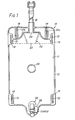
- the drainage bag 10 of the present invention is illustrated in FIG. 1.
- the bag 10 is made from two sheets of plastic which are joined together around their edges, preferably by a weld seam 13 of the "double tramline" type.
- a number of slits 12 are provided through the superposed pair of plastic sheets 11 which constitute the walls of the bag 10.
- the slits 12 are preferably surrounded by strengthening beads 14.
- the slits 12 are provided in order that they be able to receive straps or tapes (not shown) for fastening the bag 10 to a user's leg.
- the bag 10 includes an integral inlet tube 18.
- the upper region of the bag 10 includes a non-return or anti-reflux valve 20.
- the anti-reflux valve 20 is preferably made of a single piece of plastic, which in combination with one of the walls 11 of the bag 10, to which it is welded, as shown at 22, defines a liquid entry space immediately
- the center portion of the walls 11 of the bag 10 are preferably welded together using a closed-loop weld 26 which is typically of circular configuration.
- the weld 26 prevents undue "pouching” or “bulging” of the bag 10 as the bag 10 fills with liquid.
- While the bag 10 is generally rectangular, its lower region has a downwardly extending extension 28 to receive the tap 30 which is welded or otherwise secured thereto.
- the tap 30 is comprised of a body 35, shown in FIGS. 2 and 3, and a valve member 51, shown in FIGS. 4 and 5.
- the valve body 35 is preferably made of platic, and it is typically injection molded.
- the valve body 35 includes a generally cylindrical recess 32, and the substantially cylindrical wall 34 of the recess 32 is attached to, or integral with, a flat flange 36.
- the recess 32 is closed by a top wall 38.
- An external rib 40 is integral with the wall 34 and merges into the flange 36.
- a liquid exit port 37 extends through the flange 36 and opens into the recess 32.
- the liquid exit port 37 is aligned with a hole or aperture (not shown) which is pre-punched in the wall 11 of the bag 10.
- a liquid communication path extends from the interior of the bag 10 to the recess 32.
- the valve member shown 51 may also be injection molded from plastic.
- the valve member 51 includes a substantially tubular hollow housing 50 closed at one end by a wall 52.
- the valve member 51 has an arm 54 which extends radially outwardly therefrom.
- a flat handle 56 is formed as an integral part of the arm 54 and extends upwardly therefrom.
- the handle 56 serves as a deformable portion of the valve member 51.
- the handle 56 has a detent surface 58 positioned for engagement with a cooperating detent surface 60 on the rib 40 of the valve body 35. As illustrated in FIG. 5, one surface of the handle 56 bears the legend "closed” and the other (non-visible) surface bears the legend "open”.
- a liquid exit port 62 is provided in the housing 50.
- the liquid exit port 62 registers with the liquid exit port 37 when the valve member 51 is in one rotational position relative to the valve body 35.
- the liquid exit port 62 is closed off by the valve body 35 when the valve member 51 is in the other rotational position relative to the valve body 35.
- the handle 56 is moved between its two possible limit positions. At one limit position, the handle 56 is generally parallel to the flange 36 on one side of the central axis of the valve body 35. In the other position, the handle 56 is generally parallel to the flange 36 on the other side of the central axis of the valve body 35.
- the ports 37, 62 are not aligned, so the-"closed” legend is exposed.
- the apparatus of the present invention is particularly convenient to use and is easy to operate, even by old and infirm people.
- the clear legend on the handle 56 avoids any confusion as to whether the tap 30 is closed or open.
- valve member 51 If it is desired to separate the valve member 51 from the valve body 35, for cleaning, for example, then the handle 56 is deformed away from the housing 50 so that the detent surfaces 58, 60 are disengaged. When disengaged, the valve member 51 is readily withdrawn axially downwards.
- a land 66 of short axial length is preferably provided on the external cylindrical surface of the valve member 51, in order to improve the retention of the valve member 51 in the valve body 35.
- the cylindrical wall 34 has a hole 80 formed therethrough.
- the hole 80 is covered by a pad 82 of air-permeable material.
- the air-permeable pad 82 may be impregnated with a bacteriacide or an odor removing substance.
- the pad 82 is attached to the cylindrical wall 34 in any desired manner.
- an adhesive material is used to attach the pad 82 to the body 34.
- the hole 80 is located so that it is aligned with the hole 62 when the handle 56 is in its closed position, and, as shown in FIG. 6, the hole 80 is shut off when the handle 56 is in its open position.
- the tap When the tap is closed, air can enter the interior of the valve member 50, and can thereby enter the interior of a drainage tube extending down from the tap outlet. In this way, there is no build-up of negative pressure in the drainage tube, a condition known as "pooling". At the same time, no liquid can exit through the hole 80.
- the invention as particularly disclosed and illustrated herein provides a simple two-part tap which can readily be mass produced, which can readily be rapidly fixed to a drainage bag, and which is simple, easy, and relatively foolproof to operate.
Landscapes
- Health & Medical Sciences (AREA)
- Heart & Thoracic Surgery (AREA)
- Vascular Medicine (AREA)
- Engineering & Computer Science (AREA)
- Anesthesiology (AREA)
- Biomedical Technology (AREA)
- Hematology (AREA)
- Life Sciences & Earth Sciences (AREA)
- Animal Behavior & Ethology (AREA)
- General Health & Medical Sciences (AREA)
- Public Health (AREA)
- Veterinary Medicine (AREA)
- Self-Closing Valves And Venting Or Aerating Valves (AREA)
- Devices For Dispensing Beverages (AREA)
- Valve Housings (AREA)
- Check Valves (AREA)
- Bag Frames (AREA)
Priority Applications (1)
| Application Number | Priority Date | Filing Date | Title |
|---|---|---|---|
| AT82303167T ATE23949T1 (de) | 1981-06-30 | 1982-06-17 | Hahn fuer drainagesack. |
Applications Claiming Priority (4)
| Application Number | Priority Date | Filing Date | Title |
|---|---|---|---|
| GB8120082 | 1981-06-30 | ||
| GB8120082 | 1981-06-30 | ||
| GB8138193 | 1981-12-18 | ||
| GB08138193A GB2101274B (en) | 1981-06-30 | 1981-12-18 | Tap for drainage bag |
Publications (2)
| Publication Number | Publication Date |
|---|---|
| EP0068744A1 true EP0068744A1 (fr) | 1983-01-05 |
| EP0068744B1 EP0068744B1 (fr) | 1986-12-03 |
Family
ID=26279960
Family Applications (1)
| Application Number | Title | Priority Date | Filing Date |
|---|---|---|---|
| EP82303167A Expired EP0068744B1 (fr) | 1981-06-30 | 1982-06-17 | Robinet pour sac de drainage |
Country Status (5)
| Country | Link |
|---|---|
| EP (1) | EP0068744B1 (fr) |
| AU (1) | AU551428B2 (fr) |
| CA (1) | CA1185497A (fr) |
| DE (1) | DE3274521D1 (fr) |
| GB (1) | GB2101274B (fr) |
Cited By (4)
| Publication number | Priority date | Publication date | Assignee | Title |
|---|---|---|---|---|
| EP0286229A1 (fr) * | 1987-03-09 | 1988-10-12 | E.R. Squibb & Sons, Inc. | Robinet pour une poche de drainage |
| EP0879586A3 (fr) * | 1997-05-21 | 1999-01-07 | Bristol-Myers Squibb Company | Robinet pour une poche de drainage et méthode d'assemblage |
| CN109641086A (zh) * | 2016-07-06 | 2019-04-16 | 塞雷斯公司 | 用于医疗或外科手术的收集衬管 |
| GB2612611A (en) * | 2021-11-05 | 2023-05-10 | Salts Healthcare Ltd | A waste collection bag |
Families Citing this family (3)
| Publication number | Priority date | Publication date | Assignee | Title |
|---|---|---|---|---|
| GB2166222B (en) * | 1984-10-25 | 1989-05-17 | Pharma Plast As | A tap |
| GB2168459B (en) * | 1984-12-06 | 1988-07-13 | Craig Med Prod Ltd | Tube closure device |
| USD511299S1 (en) * | 2004-04-30 | 2005-11-08 | Angeletta Joseph G | Liquid soap container |
Citations (7)
| Publication number | Priority date | Publication date | Assignee | Title |
|---|---|---|---|---|
| GB920618A (en) * | 1960-10-24 | 1963-03-13 | Yorkshire Imp Metals Ltd | Combined fluid flow control and bleed valve |
| CH398225A (de) * | 1961-07-03 | 1965-08-31 | Waddington & Duval Holdings | Hahn |
| US3952727A (en) * | 1973-09-27 | 1976-04-27 | Hollister Incorporated | Vent device for ostomy appliance |
| US4055179A (en) * | 1975-03-31 | 1977-10-25 | Plastronics, Inc. | Valve for urinary drainage container or similar article |
| GB2061466A (en) * | 1979-10-22 | 1981-05-13 | Hollister Inc | Valved drain assembly for urostomy pouch |
| GB2080247A (en) * | 1980-07-25 | 1982-02-03 | Craig Med Prod Ltd | Bag with hanger |
| US4333480A (en) * | 1980-04-11 | 1982-06-08 | The Kendall Company | Urine receptacle with a tubular section to retain an antimicrobial agent |
-
1981
- 1981-12-18 GB GB08138193A patent/GB2101274B/en not_active Expired
-
1982
- 1982-06-17 EP EP82303167A patent/EP0068744B1/fr not_active Expired
- 1982-06-17 DE DE8282303167T patent/DE3274521D1/de not_active Expired
- 1982-06-23 AU AU85172/82A patent/AU551428B2/en not_active Expired
- 1982-06-30 CA CA000406434A patent/CA1185497A/fr not_active Expired
Patent Citations (7)
| Publication number | Priority date | Publication date | Assignee | Title |
|---|---|---|---|---|
| GB920618A (en) * | 1960-10-24 | 1963-03-13 | Yorkshire Imp Metals Ltd | Combined fluid flow control and bleed valve |
| CH398225A (de) * | 1961-07-03 | 1965-08-31 | Waddington & Duval Holdings | Hahn |
| US3952727A (en) * | 1973-09-27 | 1976-04-27 | Hollister Incorporated | Vent device for ostomy appliance |
| US4055179A (en) * | 1975-03-31 | 1977-10-25 | Plastronics, Inc. | Valve for urinary drainage container or similar article |
| GB2061466A (en) * | 1979-10-22 | 1981-05-13 | Hollister Inc | Valved drain assembly for urostomy pouch |
| US4333480A (en) * | 1980-04-11 | 1982-06-08 | The Kendall Company | Urine receptacle with a tubular section to retain an antimicrobial agent |
| GB2080247A (en) * | 1980-07-25 | 1982-02-03 | Craig Med Prod Ltd | Bag with hanger |
Cited By (6)
| Publication number | Priority date | Publication date | Assignee | Title |
|---|---|---|---|---|
| EP0286229A1 (fr) * | 1987-03-09 | 1988-10-12 | E.R. Squibb & Sons, Inc. | Robinet pour une poche de drainage |
| EP0879586A3 (fr) * | 1997-05-21 | 1999-01-07 | Bristol-Myers Squibb Company | Robinet pour une poche de drainage et méthode d'assemblage |
| CN109641086A (zh) * | 2016-07-06 | 2019-04-16 | 塞雷斯公司 | 用于医疗或外科手术的收集衬管 |
| US11129928B2 (en) | 2016-07-06 | 2021-09-28 | Serres Oy | Assembly for collecting fluid during a medical or a surgical operation |
| US11285255B2 (en) | 2016-07-06 | 2022-03-29 | Serres Oy | Collection liner for a medical or a surgical operation |
| GB2612611A (en) * | 2021-11-05 | 2023-05-10 | Salts Healthcare Ltd | A waste collection bag |
Also Published As
| Publication number | Publication date |
|---|---|
| GB2101274A (en) | 1983-01-12 |
| EP0068744B1 (fr) | 1986-12-03 |
| AU8517282A (en) | 1983-01-06 |
| DE3274521D1 (en) | 1987-01-15 |
| CA1185497A (fr) | 1985-04-16 |
| GB2101274B (en) | 1985-07-10 |
| AU551428B2 (en) | 1986-05-01 |
Similar Documents
| Publication | Publication Date | Title |
|---|---|---|
| US4462510A (en) | Tap for drainage bag | |
| EP0286229B1 (fr) | Robinet pour une poche de drainage | |
| US4516973A (en) | One-piece disposable collection bag having a rigid cover for a suction canister unit | |
| CA1151970A (fr) | Dispositif de fermeture frangible sur tube souple | |
| US4828546A (en) | Bulb evacuator for closed wound suction | |
| US4451258A (en) | Ostomy bag with an adjustable vent | |
| US4397442A (en) | In-line sleeve valve | |
| US4346711A (en) | Body fluid collection device with disposable liner | |
| US3998255A (en) | Breather assembly for a sealed container | |
| US4955873A (en) | Stabilizing support stand | |
| US3232467A (en) | Nursing device | |
| CN112469452A (zh) | 用于吸乳泵的容器组件 | |
| US4863447A (en) | Valved vent assembly for a body collection pouch | |
| US20040140314A1 (en) | Non-spillable beverage container and straw | |
| EP0068744A1 (fr) | Robinet pour sac de drainage | |
| CN1326508C (zh) | 用于袋囊的焊接船形件和具有焊接船形件的袋囊 | |
| EP0588462A2 (fr) | Système d'admission de produit chimique | |
| US4526576A (en) | Liquid drainage system with interlocked handle | |
| US3228444A (en) | Specimen container | |
| CA2077492C (fr) | Trousse de radiologie, et methode d'utilisation | |
| US4417891A (en) | Collection device with antiseptic liquid for body fluids | |
| JPH02220647A (ja) | 人工肛門用カップリング | |
| JPS5813837A (ja) | 排液袋用水栓 | |
| JPH0362093B2 (fr) | ||
| JP4486679B2 (ja) | ドレナージバッグ |
Legal Events
| Date | Code | Title | Description |
|---|---|---|---|
| PUAI | Public reference made under article 153(3) epc to a published international application that has entered the european phase |
Free format text: ORIGINAL CODE: 0009012 |
|
| AK | Designated contracting states |
Designated state(s): AT BE CH DE FR GB IT LI LU NL SE |
|
| 17P | Request for examination filed |
Effective date: 19830623 |
|
| 18W | Application withdrawn |
Withdrawal date: 19860618 |
|
| D18W | Application withdrawn (deleted) | ||
| GRAA | (expected) grant |
Free format text: ORIGINAL CODE: 0009210 |
|
| ITF | It: translation for a ep patent filed | ||
| AK | Designated contracting states |
Kind code of ref document: B1 Designated state(s): AT BE CH DE FR IT LI LU NL SE |
|
| REF | Corresponds to: |
Ref document number: 23949 Country of ref document: AT Date of ref document: 19861215 Kind code of ref document: T |
|
| ET | Fr: translation filed | ||
| REF | Corresponds to: |
Ref document number: 3274521 Country of ref document: DE Date of ref document: 19870115 |
|
| PLBE | No opposition filed within time limit |
Free format text: ORIGINAL CODE: 0009261 |
|
| STAA | Information on the status of an ep patent application or granted ep patent |
Free format text: STATUS: NO OPPOSITION FILED WITHIN TIME LIMIT |
|
| 26N | No opposition filed | ||
| ITTA | It: last paid annual fee | ||
| EPTA | Lu: last paid annual fee | ||
| EAL | Se: european patent in force in sweden |
Ref document number: 82303167.9 |
|
| PGFP | Annual fee paid to national office [announced via postgrant information from national office to epo] |
Ref country code: LU Payment date: 20000609 Year of fee payment: 19 |
|
| PGFP | Annual fee paid to national office [announced via postgrant information from national office to epo] |
Ref country code: AT Payment date: 20000613 Year of fee payment: 19 |
|
| PGFP | Annual fee paid to national office [announced via postgrant information from national office to epo] |
Ref country code: CH Payment date: 20000628 Year of fee payment: 19 |
|
| PGFP | Annual fee paid to national office [announced via postgrant information from national office to epo] |
Ref country code: BE Payment date: 20000818 Year of fee payment: 19 |
|
| PGFP | Annual fee paid to national office [announced via postgrant information from national office to epo] |
Ref country code: SE Payment date: 20010417 Year of fee payment: 20 |
|
| PGFP | Annual fee paid to national office [announced via postgrant information from national office to epo] |
Ref country code: FR Payment date: 20010611 Year of fee payment: 20 Ref country code: DE Payment date: 20010611 Year of fee payment: 20 |
|
| PG25 | Lapsed in a contracting state [announced via postgrant information from national office to epo] |
Ref country code: LU Free format text: LAPSE BECAUSE OF NON-PAYMENT OF DUE FEES Effective date: 20010617 Ref country code: AT Free format text: LAPSE BECAUSE OF NON-PAYMENT OF DUE FEES Effective date: 20010617 |
|
| PGFP | Annual fee paid to national office [announced via postgrant information from national office to epo] |
Ref country code: NL Payment date: 20010628 Year of fee payment: 20 |
|
| PG25 | Lapsed in a contracting state [announced via postgrant information from national office to epo] |
Ref country code: LI Free format text: LAPSE BECAUSE OF NON-PAYMENT OF DUE FEES Effective date: 20010630 Ref country code: CH Free format text: LAPSE BECAUSE OF NON-PAYMENT OF DUE FEES Effective date: 20010630 Ref country code: BE Free format text: LAPSE BECAUSE OF NON-PAYMENT OF DUE FEES Effective date: 20010630 |
|
| BERE | Be: lapsed |
Owner name: CRAIG MEDICAL PRODUCTS LTD Effective date: 20010630 |
|
| REG | Reference to a national code |
Ref country code: CH Ref legal event code: PL |
|
| PG25 | Lapsed in a contracting state [announced via postgrant information from national office to epo] |
Ref country code: NL Free format text: LAPSE BECAUSE OF EXPIRATION OF PROTECTION Effective date: 20020617 |
|
| EUG | Se: european patent has lapsed |
Ref document number: 82303167.9 |
|
| NLV7 | Nl: ceased due to reaching the maximum lifetime of a patent |
Effective date: 20020617 |