EP0068929A2 - Dispositif à utiliser pour maintenir en équilibre un élément suspendu et déplaçable en hauteur, tel q'un téléscope associé à un porte-tube Rontgen - Google Patents
Dispositif à utiliser pour maintenir en équilibre un élément suspendu et déplaçable en hauteur, tel q'un téléscope associé à un porte-tube Rontgen Download PDFInfo
- Publication number
- EP0068929A2 EP0068929A2 EP82400987A EP82400987A EP0068929A2 EP 0068929 A2 EP0068929 A2 EP 0068929A2 EP 82400987 A EP82400987 A EP 82400987A EP 82400987 A EP82400987 A EP 82400987A EP 0068929 A2 EP0068929 A2 EP 0068929A2
- Authority
- EP
- European Patent Office
- Prior art keywords
- gas spring
- suspended
- height
- reel
- cable
- Prior art date
- Legal status (The legal status is an assumption and is not a legal conclusion. Google has not performed a legal analysis and makes no representation as to the accuracy of the status listed.)
- Withdrawn
Links
- 230000007246 mechanism Effects 0.000 claims abstract description 6
- 230000005540 biological transmission Effects 0.000 claims abstract description 4
- 230000003472 neutralizing effect Effects 0.000 abstract 1
- 241000581464 Dactyloscopidae Species 0.000 description 2
- 230000006835 compression Effects 0.000 description 1
- 238000007906 compression Methods 0.000 description 1
- 238000006073 displacement reaction Methods 0.000 description 1
Images

Classifications
-
- A—HUMAN NECESSITIES
- A61—MEDICAL OR VETERINARY SCIENCE; HYGIENE
- A61B—DIAGNOSIS; SURGERY; IDENTIFICATION
- A61B6/00—Apparatus or devices for radiation diagnosis; Apparatus or devices for radiation diagnosis combined with radiation therapy equipment
- A61B6/44—Constructional features of apparatus for radiation diagnosis
- A61B6/4429—Constructional features of apparatus for radiation diagnosis related to the mounting of source units and detector units
- A61B6/447—Constructional features of apparatus for radiation diagnosis related to the mounting of source units and detector units the source unit or the detector unit being mounted to counterpoise or springs
-
- B—PERFORMING OPERATIONS; TRANSPORTING
- B23—MACHINE TOOLS; METAL-WORKING NOT OTHERWISE PROVIDED FOR
- B23Q—DETAILS, COMPONENTS, OR ACCESSORIES FOR MACHINE TOOLS, e.g. ARRANGEMENTS FOR COPYING OR CONTROLLING; MACHINE TOOLS IN GENERAL CHARACTERISED BY THE CONSTRUCTION OF PARTICULAR DETAILS OR COMPONENTS; COMBINATIONS OR ASSOCIATIONS OF METAL-WORKING MACHINES, NOT DIRECTED TO A PARTICULAR RESULT
- B23Q11/00—Accessories fitted to machine tools for keeping tools or parts of the machine in good working condition or for cooling work; Safety devices specially combined with or arranged in, or specially adapted for use in connection with, machine tools
- B23Q11/001—Arrangements compensating weight or flexion on parts of the machine
-
- F—MECHANICAL ENGINEERING; LIGHTING; HEATING; WEAPONS; BLASTING
- F16—ENGINEERING ELEMENTS AND UNITS; GENERAL MEASURES FOR PRODUCING AND MAINTAINING EFFECTIVE FUNCTIONING OF MACHINES OR INSTALLATIONS; THERMAL INSULATION IN GENERAL
- F16M—FRAMES, CASINGS OR BEDS OF ENGINES, MACHINES OR APPARATUS, NOT SPECIFIC TO ENGINES, MACHINES OR APPARATUS PROVIDED FOR ELSEWHERE; STANDS; SUPPORTS
- F16M11/00—Stands or trestles as supports for apparatus or articles placed thereon ; Stands for scientific apparatus such as gravitational force meters
- F16M11/02—Heads
- F16M11/18—Heads with mechanism for moving the apparatus relatively to the stand
-
- F—MECHANICAL ENGINEERING; LIGHTING; HEATING; WEAPONS; BLASTING
- F16—ENGINEERING ELEMENTS AND UNITS; GENERAL MEASURES FOR PRODUCING AND MAINTAINING EFFECTIVE FUNCTIONING OF MACHINES OR INSTALLATIONS; THERMAL INSULATION IN GENERAL
- F16M—FRAMES, CASINGS OR BEDS OF ENGINES, MACHINES OR APPARATUS, NOT SPECIFIC TO ENGINES, MACHINES OR APPARATUS PROVIDED FOR ELSEWHERE; STANDS; SUPPORTS
- F16M11/00—Stands or trestles as supports for apparatus or articles placed thereon ; Stands for scientific apparatus such as gravitational force meters
- F16M11/20—Undercarriages with or without wheels
- F16M11/24—Undercarriages with or without wheels changeable in height or length of legs, also for transport only, e.g. by means of tubes screwed into each other
- F16M11/26—Undercarriages with or without wheels changeable in height or length of legs, also for transport only, e.g. by means of tubes screwed into each other by telescoping, with or without folding
- F16M11/28—Undercarriages for supports with one single telescoping pillar
-
- F—MECHANICAL ENGINEERING; LIGHTING; HEATING; WEAPONS; BLASTING
- F16—ENGINEERING ELEMENTS AND UNITS; GENERAL MEASURES FOR PRODUCING AND MAINTAINING EFFECTIVE FUNCTIONING OF MACHINES OR INSTALLATIONS; THERMAL INSULATION IN GENERAL
- F16M—FRAMES, CASINGS OR BEDS OF ENGINES, MACHINES OR APPARATUS, NOT SPECIFIC TO ENGINES, MACHINES OR APPARATUS PROVIDED FOR ELSEWHERE; STANDS; SUPPORTS
- F16M2200/00—Details of stands or supports
- F16M2200/04—Balancing means
- F16M2200/047—Balancing means for balancing translational movement of the head
Definitions
- the subject of the invention is a device to be used for keeping in balance an element suspended in a Rôntgen device and movable in height by hand, namely a device such as a telescope with Rôntgen tube holder, a video amplifier, a image receptor and the like.
- the suspended element is relatively heavy, we are forced to use heavy and bulky mechanisms to be able to keep everything in balance. It follows that the cost price of these devices is quite high. Furthermore, these are not always effective and the manual adjustment of the movable elements in height cannot always be carried out in a precise manner.
- a device which, in main order comprises a "gas spring” or a cylinder filled with a gas under pressure and operating in two directions, cylinder completed by a piston and a piston rod, this to keep in balance the suspended element, a servomotor necessary to neutralize the friction force of the piston in the "gas spring” during the manual displacement in height of the suspended element, a means of compensation necessary to compensate in all positions of the "gas spring” the variable forces thereof and therefore be able to maintain constantly in equilibrium in all its height positions, the suspended element, the above-mentioned device further comprising a transmission mechanism placed between the suspended element, the "gas spring", the compensation means and the servomotor.
- This device therefore has the advantage of being very compact, of not being heavy and of being inexpensive in its execution.
- the flexible and extendable lower part of the telescope 1 on which it is mounted in the present case is suspended from a traction cable 3 fixed to a cable reel 4 of eccentric shape and can be rolled up thereon.
- This eccentric cable reel 4 is mounted on the axis 5 of a booster 6, so as to be integral with this axis.
- two reels 7 are also mounted, so as to also be integral with this axis.
- a cable 8-9 is attached to each of these reels 7, respectively, these cables each being attached to a cross member 10, mounted on the piston rod 11, with a gas spring 12 which keeps everything in place. balanced.
- a push button 13 which is used to start the servomotor 6 and switch it off.
- the dimensions and the shape of the cable reel 4 of eccentric shape on which the traction cable 3 is wound are chosen so that in any position occupied by the piston rod 11 relative to the cylinder 15 of the gas spring 12 and in which the force exerted by the gas spring varies, the traction force or the compression force to be exerted on the telescope 1 to be displaced in height and on the traction cable 3, are however always constant, this so as to reach in all positions of telescopes 1, perfect balance.
- the servomotor 6 In order to be able to easily handle the telescope 1 without having to exert an exaggerated manual force and to regulate in a precise way and at a determined height the tube holder Rôntgen 2 suspended there and the lamp Rôntgen, there is provided the servomotor 6 to ensure that that the friction resistance of the gas spring 12 is overcome at each movement of the telescope 1.
- the telescope 1 For the height adjustment of the tube holder Rôntgen 2, push the button 13 mounted on the panel 14 and thus the motor 6 starts and the telescope 1 is retracted or removed. hand.
- the friction resistance of the gas spring 12 is immediately overcome by the booster 6, the force to be exerted by it is just sufficient to neutralize this resistance.
- the telescope 1 can then be placed without difficulty in a determined position while the cables 8 - 9 are wound on the reels 7 or unwound therefrom and that the traction cable 3 is wound on the cable reel 4 or deflected of it by the tensile force of the gas spring 12 which keeps everything in balance.
- the eccentrically shaped cable reel 4 ensures that the pulling force exerted on the pulling cable 3 is always constant, so that the telescope 1 can be adjusted in height in any height position by means of the same manual force.
Landscapes
- Engineering & Computer Science (AREA)
- General Engineering & Computer Science (AREA)
- Mechanical Engineering (AREA)
- Health & Medical Sciences (AREA)
- Life Sciences & Earth Sciences (AREA)
- Medical Informatics (AREA)
- Optics & Photonics (AREA)
- Biomedical Technology (AREA)
- Biophysics (AREA)
- Nuclear Medicine, Radiotherapy & Molecular Imaging (AREA)
- Physics & Mathematics (AREA)
- Pathology (AREA)
- Radiology & Medical Imaging (AREA)
- High Energy & Nuclear Physics (AREA)
- Heart & Thoracic Surgery (AREA)
- Molecular Biology (AREA)
- Surgery (AREA)
- Animal Behavior & Ethology (AREA)
- General Health & Medical Sciences (AREA)
- Public Health (AREA)
- Veterinary Medicine (AREA)
- Apparatus For Radiation Diagnosis (AREA)
Abstract
Le dispositif susdit comporte en ordre principal un «ressort gazeux» (12) pour maintenir en équilibre l'élément suspendu (1), un servomoteur (6) pour neutraliser la force de frottement du «ressort gazeux» (12), un moyen de compensation (4) pour compenser dans toutes les positions du «ressort gazeux» (12) les forces variables de celui-ci et pouvoir en conséquence maintenir constamment en équilibre l'élément (1) suspendu, ledit dispositif comprenant en plus un mécanisme de transmission (3 - 5 - 7 - 8 - 9 - 10) placé entre l'élément suspendu (1), le «ressort gazeux» (12), le moyen de compensation (4) et le servomoteur (6)
Description
- L'invention a pour objet un dispositif à utiliser pour maintenir en 'équilibre un élément suspendu dans un appareil Rôntgen et déplaçable en hauteur à la main, à savoir un appareil tel qu'un télescope avec porte-tube Rôntgen, un amplificateur vidéo, un récepteur d'images et appareils analogues.
- On connaît des dispositifs dans lesquels il est fait usage d'un mécanisme à câble et à ressorts en spirale ou à ressorts de traction ou d'un moteur, placé entre l'élément déplaçable en hauteur et la partie fixe de l'appareil, cela pour maintenir en équilibre l'élément susnommé.
- Attendu que, dans de nombreux cas, l'élément suspendu est relativement lourd, on est forcé d'utiliser des mécanismes lourds et volumineux pour pouvoir maintenir le tout en équilibre. Il s'ensuit que le prix de revient de ces dispositifs est assez élevé. Ceux-ci ne sont en outre pas toujours efficaces et le réglage manuel des éléments déplaçables en hauteur ne peut pas toujours d'effectuer d'une manière précise.
- Suivant la caractéristique principale de l'invention et pour obvier à ces inconvénients, on a réalisé un dispositif qui, en ordre principal comporte un "ressort gazeux" ou un cylindre rempli d'un gaz sous pression et fonctionnant dans deux directions, cylindre complété par un piston et une bielle de piston, cela pour maintenir en équilibre l'élément suspendu, un servomoteur nécessaire pour neutraliser la force de frottement du piston dans le "ressort gazeux" pendant le déplacement manuel en hauteur de l'élément suspendu, un moyen de compensation nécessaire pour compenser dans toutes les positions du "ressort gazeux" les forces variables de celui-ci et pouvoir en conséquence maintenir constamment en équilibre dans toutes ses positions en hauteur, l'élément suspendu, le dispositif susdit comportant en plus un mécanisme de transmission placé entre l'élément suspendu, le "ressort gazeux", le moyen de compensation et le servomoteur.
- Ce dispositif a donc l'avantage d'être très compact, de n'être pas lours et d'être bon marché dans son exécution.
- Le texte ci-après fournit à titre d'exemple une description plus détaillée d'une forme de réalisation du dispositif susdit conforme à l'invention, une telle forme n'étant qu'une forme possible de celle-ci mais en aucune façon limitée à celle-ci. A la susdite description, il est joint des dessins dans lesquels :
- - la figure 1 représente schématiquement, en perspective, le dispositif susdit ;
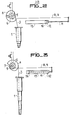
- - la figure 2, une vue schématique du dispositif susdit, à savoir une vue, dans laquelle le télescope suspendu est représenté en position "rentrée" ;
- - la figure 3 est une vue schématique du dispositif susdit, à savoir une vue dans laquelle le télescope suspendu est représenté en position "retirée"
- Dans ces figures, on remarque que la partie inférieure ren- trable et extensible du télescope 1 sur laquelle il est monté dans le présent cas un porte-tube Rôntgen 2, est suspendue à un câble de traction 3 fixé à un enrouleur de câble 4 de forme excentrique et pouvant être enroulé sur celui-ci. Cet enrouleur de câble 4 de forme excentrique est monté sur l'axe 5 d'un servomoteur 6, de manière à être solidaire de cet axe. Sur l'axe 5, il est également monté deux enrouleurs 7, de manière à être également solidaires de cet axe. A chacun de ces enrouleurs 7, il est fixé un câble respectivement 8 - 9, ces câbles étant d'autre part chacun attachés à une traverse 10, montée sur la bielle de piston 11, d'un ressort gazeux 12 qui maintient le tout en équilibre. Il est placé sur le panneau 14 de l'appareil, un bouton-poussoir 13 qui sert à faire démarrer le servomoteur 6 et à le mettre à l'arrêt. Les dimensions et la forme de l'enrouleur de câble 4 de forme excentrique sur lequel le câble de traction 3 est enroulé sont choisies de telle manière que dans une position quelconque, occupée par la bielle 11 de piston par rapport au cylindre 15 du ressort gazeux 12 et dans laquelle la force exercée par le ressort gazeux varie, la force de traction ou la force de compression à exercer sur le télescope 1 à déplacer en hauteur et sur le câble à traction 3, soient cependant toujours constantes, cela de manière à atteindre dans toutes les positions du télescopes 1, un équilibre parfait. Pour pouvoir manier facilement le télescope 1 sans devoir dépenser une force manuelle exagérée et pour régler d'une manière précise et à une hauteur déterminée le porte-tube Rôntgen 2 y suspendu et la lampe Rôntgen, il est prévu le servomoteur 6 pour veiller à ce que la résistance de frottement du ressort gazeux 12 soit vaincue à chaque déplacement du télescope 1.
- Pour le réglage en hauteur du porte-tube Rôntgen 2, on enfonce le bouton-poussoir 13 monté sur le panneau 14 et ainsi le moteur 6 démarre et le télescope 1 est rentré ou retiré à la. main. La résistance de frottement du ressort gazeux 12 est immédiatement vaincue par le servomoteur 6 dont la force à exercer par lui est juste suffisante pour neutraliser cette résistance. Le télescope 1 peut être alors placé sans peine dans une position déterminée tandis que les câbles 8 - 9 sont enroulés sur les enrouleurs 7 ou dévidés de ceux-ci et que le câble de traction 3 est enroulé sur l'enrouleur de câble 4 ou dévié de celui-ci par la force de traction du ressort gazeux 12 qui maintient le tout en équilibre. L'enrouleur de câble 4 de forme excentrique veille à ce que la force de traction exercée sur le câble de traction 3 soit toujours constante, cela de telle manière que le télescope 1 puisse être réglé en hauteur dans toutes positions en hauteur au moyen d'une même force manuelle.
- Il va sans dire que la forme, les dimensions et le montage mutuel de ces éléments ci-avant décrits peuvent différer et que des pièces déterminées pourraient être remplacées par d'autres équivalentes, cela à condition de ne pas sortir du cadre de l'invention.
Claims (4)
1. Dispositif à utiliser pour maintenir en équilibre un élément suspendu et déplaçable en hauteur, par exemple un élément tel qu'un télescope (1) avec porte-tube Rôntgen (2), caractérisé par le fait qu'en ordre principal, le dispositif susdit comporte un "ressort gazeux" (I2) pour maintenir en équilibre l'élément suspendu (1), un servomoteur (6) pour neutraliser la force de frottement du piston (16) dans le "ressort gazeux" (12) pendant le déplacement manuel en hauteur de l'élément suspendu (1), un moyen de compensation (4) pour compenser dans toutes les positions du "ressort gazeux" (12) les forces variables de celui-ci et pour maintenir constamment en équilibre dans toutes ses positions en hauteur l'élément suspendu, et un mécanisme de transmission (3 - 5 - 7 - 8 - 9 - 10) placé entre l'élément suspendu (1), le "ressort gazeux" (12), le moyen de compensation (4) et le servomoteur (6).
2. Dispositif conforme à la revendication 1, caractérisé par le fait que le mécanisme de transmission comporte un axe de rotation (5), au moins un enrouleur (7) fixé sur cet axe de rotation (5), au moins un câble (8 - 9) prévu entre l'enrouleur (7) et la bielle de piston (11) du "ressort gazeux" (12), tandis que sont couplés à l'axe de rotation (5) le moyen de compensation (4) et le servomoteur (6).
3. Dispositif conforme à la revendication 2, caractérisé par le fait que le moyen de compensation comporte un enrouleur de câble (4) de forme excentrique fixé sur l'axe de rotation (5), auquel enrouleur est fixé un câble de traction (3) .auquel est suspendu l'élément (1) réglable en hauteur.
4. Dispositif conforme à la revendication 2, caractérisé par le fait que sur l'axe de rotation (5) sont fixés deux enrouleurs (7), tandis qu'à chaque enrouleur (7) il est fixé un câble (8 -9) fixé d'autre part à une traverse (10) montée sur la bielle de piston (11) du "ressort gazeux" (12).
Applications Claiming Priority (2)
| Application Number | Priority Date | Filing Date | Title |
|---|---|---|---|
| BE2/59205A BE889158A (nl) | 1981-06-10 | 1981-06-10 | Inrichting voor het in evenwicht houden van een in rontgenapparaat opgehangen en in hoogte verplaatsbaar onderdeel, zoals een telescoop met rontgenbuisdrager |
| BE2059205 | 1981-06-10 |
Publications (2)
| Publication Number | Publication Date |
|---|---|
| EP0068929A2 true EP0068929A2 (fr) | 1983-01-05 |
| EP0068929A3 EP0068929A3 (fr) | 1983-10-19 |
Family
ID=3865555
Family Applications (1)
| Application Number | Title | Priority Date | Filing Date |
|---|---|---|---|
| EP82400987A Withdrawn EP0068929A3 (fr) | 1981-06-10 | 1982-05-27 | Dispositif à utiliser pour maintenir en équilibre un élément suspendu et déplaçable en hauteur, tel q'un téléscope associé à un porte-tube Rontgen |
Country Status (1)
| Country | Link |
|---|---|
| EP (1) | EP0068929A3 (fr) |
Cited By (3)
| Publication number | Priority date | Publication date | Assignee | Title |
|---|---|---|---|---|
| FR2564357A1 (fr) * | 1984-05-17 | 1985-11-22 | Berthiez Saint Etienne | Dispositif d'equilibrage d'organes et machines-outils ayant un deplacement vertical |
| EP0326859A3 (en) * | 1988-02-02 | 1990-07-11 | Kabushiki Kaisha Toshiba | Table equipment |
| WO2006085156A2 (fr) | 2004-11-23 | 2006-08-17 | Philips Intellectual Property & Standards Gmbh | Unite de commande pour systeme de radiologie |
Family Cites Families (10)
| Publication number | Priority date | Publication date | Assignee | Title |
|---|---|---|---|---|
| FR1039050A (fr) * | 1950-06-28 | 1953-10-05 | Philips Nv | Appareil à rayons chi |
| DE1005683B (de) * | 1953-12-12 | 1957-04-04 | Mueller C H F Ag | Stativanordnung, insbesondere fuer Roentgeneinrichtungen |
| US2892947A (en) * | 1955-08-31 | 1959-06-30 | High Voltage Engineering Corp | X-ray generator mount |
| DE1091279B (de) * | 1958-09-12 | 1960-10-20 | Picker X Ray Corp Waite Mfg Di | Hoehenverstellbare Deckenaufhaengung mit Gewichtsausgleich |
| FR1307731A (fr) * | 1961-12-08 | 1962-10-26 | Philips Nv | Dispositif support d'une charge déplaçable verticalement à la main |
| US3575368A (en) * | 1969-01-27 | 1971-04-20 | Westinghouse Electric Corp | Vertically adjustable counterbalancing x-ray tube head suspension support apparatus |
| DE2557810C3 (de) * | 1975-12-22 | 1987-07-30 | Siemens AG, 1000 Berlin und 8000 München | Stativ für ein röntgenologisches Bilderfassungsgerät |
| DE2629431C2 (de) * | 1976-06-30 | 1981-10-08 | Friedrich Wilhelm 8900 Augsburg Ortmann | Schlittenständereinheit für Sonderwerkzeugmaschinen |
| US4166602A (en) * | 1978-05-18 | 1979-09-04 | Pennwalt Corporation | Counterbalancing mechanism for X-ray tubeheads |
| FR2435242A1 (fr) * | 1978-09-05 | 1980-04-04 | Leim | Spirometres enregistreurs a cloche mobile equilibree |
-
1982
- 1982-05-27 EP EP82400987A patent/EP0068929A3/fr not_active Withdrawn
Cited By (7)
| Publication number | Priority date | Publication date | Assignee | Title |
|---|---|---|---|---|
| FR2564357A1 (fr) * | 1984-05-17 | 1985-11-22 | Berthiez Saint Etienne | Dispositif d'equilibrage d'organes et machines-outils ayant un deplacement vertical |
| EP0326859A3 (en) * | 1988-02-02 | 1990-07-11 | Kabushiki Kaisha Toshiba | Table equipment |
| WO2006085156A2 (fr) | 2004-11-23 | 2006-08-17 | Philips Intellectual Property & Standards Gmbh | Unite de commande pour systeme de radiologie |
| WO2006085156A3 (fr) * | 2004-11-23 | 2006-11-23 | Philips Intellectual Property | Unite de commande pour systeme de radiologie |
| JP2008520325A (ja) * | 2004-11-23 | 2008-06-19 | コーニンクレッカ フィリップス エレクトロニクス エヌ ヴィ | X線システムのための駆動ユニット |
| CN100563565C (zh) * | 2004-11-23 | 2009-12-02 | 皇家飞利浦电子股份有限公司 | 用于x射线系统的驱动单元 |
| US7670048B2 (en) | 2004-11-23 | 2010-03-02 | Koninklijke Philips Electronics N.V | Drive unit for X-ray system |
Also Published As
| Publication number | Publication date |
|---|---|
| EP0068929A3 (fr) | 1983-10-19 |
Similar Documents
| Publication | Publication Date | Title |
|---|---|---|
| EP0132179B1 (fr) | Table d'opération chirurgicale | |
| US4695021A (en) | Support stand with adjustable legs | |
| US5649256A (en) | Adjustable means for a monitor camera | |
| US6685149B1 (en) | Adjustable support stand | |
| FR2899309A1 (fr) | Dispositif porteur | |
| US11608934B2 (en) | Tripod for video-photographic equipment | |
| EP0272746A2 (fr) | Support orientable notamment, pour instruments d'optique et similaires | |
| FR2577376A1 (fr) | Stabilisateur lateral pour les barres inferieures d'un attelage a trois points entre un tracteur et un appareil agricole | |
| EP0080960A1 (fr) | Dispositif à mâchoires orientables, adaptable sur tout support pour assurer de manière stable un serrage, un assemblage, un écartement ou un maintien en position de pièces de formes et dimensions quelconques | |
| EP0068929A2 (fr) | Dispositif à utiliser pour maintenir en équilibre un élément suspendu et déplaçable en hauteur, tel q'un téléscope associé à un porte-tube Rontgen | |
| EP0581623A1 (fr) | Dispositif de sécurité pour lève-vitre électrique à cable de véhicule | |
| BE627435A (fr) | Détendeur de gaz pouvant faire office de robinet | |
| NO309499B1 (no) | Justeringsmekanisme for fokuseringsarm for overheadprosjektor | |
| US4919523A (en) | Telescope motorized drive attachment | |
| FR2544894A1 (fr) | Dispositif de commande mecanique a distance avec liaison flexible | |
| FR2608140A3 (fr) | Support de devidage manuel freine pour bobine de film etirable | |
| EP0289541A1 (fr) | Dispositif et appareil pour la mon uvre des volets roulants | |
| JPH0569495U (ja) | 三 脚 | |
| FR2696558A1 (fr) | Régulateur de position. | |
| EP1103444A1 (fr) | Agencement de poussoir pour carter en métal ou alliage léger de direction à crémaillère | |
| CH310120A (fr) | Dispositif pour rendre réglable l'inclinaison du dossier d'un siège tubulaire. | |
| FR2673999A1 (fr) | Dispositif de reglage d'une commande d'orientation d'un systeme optique de projecteur, en particulier pour vehicule automobile. | |
| FR2724703A1 (fr) | Outil d'ecartement de tubes telescopiques | |
| FR3025365A1 (fr) | Dispositif d’installation d’une gaine retractable sur un agencement electrique | |
| KR930002204Y1 (ko) | 삼각대의상하구동안전장치 |
Legal Events
| Date | Code | Title | Description |
|---|---|---|---|
| PUAI | Public reference made under article 153(3) epc to a published international application that has entered the european phase |
Free format text: ORIGINAL CODE: 0009012 |
|
| AK | Designated contracting states |
Designated state(s): DE FR IT NL |
|
| PUAL | Search report despatched |
Free format text: ORIGINAL CODE: 0009013 |
|
| AK | Designated contracting states |
Designated state(s): DE FR IT NL |
|
| 17P | Request for examination filed |
Effective date: 19840323 |
|
| STAA | Information on the status of an ep patent application or granted ep patent |
Free format text: STATUS: THE APPLICATION IS DEEMED TO BE WITHDRAWN |
|
| 18D | Application deemed to be withdrawn |
Effective date: 19851228 |
|
| RIN1 | Information on inventor provided before grant (corrected) |
Inventor name: MUNCH, JOSEPH |