EP0068951B1 - Gasisolierte gekapselte Zelle für elektrische Mittelspannungsanlage - Google Patents
Gasisolierte gekapselte Zelle für elektrische Mittelspannungsanlage Download PDFInfo
- Publication number
- EP0068951B1 EP0068951B1 EP19820401045 EP82401045A EP0068951B1 EP 0068951 B1 EP0068951 B1 EP 0068951B1 EP 19820401045 EP19820401045 EP 19820401045 EP 82401045 A EP82401045 A EP 82401045A EP 0068951 B1 EP0068951 B1 EP 0068951B1
- Authority
- EP
- European Patent Office
- Prior art keywords
- tank
- switch
- metal
- pole
- fact
- Prior art date
- Legal status (The legal status is an assumption and is not a legal conclusion. Google has not performed a legal analysis and makes no representation as to the accuracy of the status listed.)
- Expired
Links
- 238000010616 electrical installation Methods 0.000 title 1
- 239000004020 conductor Substances 0.000 claims description 17
- 238000009413 insulation Methods 0.000 claims description 12
- 238000007664 blowing Methods 0.000 claims description 9
- 239000002184 metal Substances 0.000 claims description 8
- 238000012360 testing method Methods 0.000 claims description 8
- 239000012212 insulator Substances 0.000 claims description 7
- 239000011810 insulating material Substances 0.000 claims description 6
- 230000007246 mechanism Effects 0.000 claims description 5
- 229910018503 SF6 Inorganic materials 0.000 claims description 2
- 239000011248 coating agent Substances 0.000 claims description 2
- 238000000576 coating method Methods 0.000 claims description 2
- SFZCNBIFKDRMGX-UHFFFAOYSA-N sulfur hexafluoride Chemical compound FS(F)(F)(F)(F)F SFZCNBIFKDRMGX-UHFFFAOYSA-N 0.000 claims description 2
- 229960000909 sulfur hexafluoride Drugs 0.000 claims description 2
- 239000000872 buffer Substances 0.000 claims 1
- 238000002955 isolation Methods 0.000 description 5
- 238000000429 assembly Methods 0.000 description 4
- 230000006835 compression Effects 0.000 description 3
- 238000007906 compression Methods 0.000 description 3
- 230000008901 benefit Effects 0.000 description 2
- 239000003990 capacitor Substances 0.000 description 2
- 239000000853 adhesive Substances 0.000 description 1
- 230000001070 adhesive effect Effects 0.000 description 1
- 230000005540 biological transmission Effects 0.000 description 1
- 238000010586 diagram Methods 0.000 description 1
- 238000006073 displacement reaction Methods 0.000 description 1
- 238000005315 distribution function Methods 0.000 description 1
- 230000000977 initiatory effect Effects 0.000 description 1
- 238000004519 manufacturing process Methods 0.000 description 1
- 239000000463 material Substances 0.000 description 1
- 230000009467 reduction Effects 0.000 description 1
- 239000004065 semiconductor Substances 0.000 description 1
- 230000009466 transformation Effects 0.000 description 1
- 238000011144 upstream manufacturing Methods 0.000 description 1
- 238000012800 visualization Methods 0.000 description 1
Images




Classifications
-
- H—ELECTRICITY
- H02—GENERATION; CONVERSION OR DISTRIBUTION OF ELECTRIC POWER
- H02B—BOARDS, SUBSTATIONS OR SWITCHING ARRANGEMENTS FOR THE SUPPLY OR DISTRIBUTION OF ELECTRIC POWER
- H02B13/00—Arrangement of switchgear in which switches are enclosed in, or structurally associated with, a casing, e.g. cubicle
- H02B13/02—Arrangement of switchgear in which switches are enclosed in, or structurally associated with, a casing, e.g. cubicle with metal casing
- H02B13/035—Gas-insulated switchgear
- H02B13/0358—Connections to in or out conductors
-
- H—ELECTRICITY
- H02—GENERATION; CONVERSION OR DISTRIBUTION OF ELECTRIC POWER
- H02B—BOARDS, SUBSTATIONS OR SWITCHING ARRANGEMENTS FOR THE SUPPLY OR DISTRIBUTION OF ELECTRIC POWER
- H02B13/00—Arrangement of switchgear in which switches are enclosed in, or structurally associated with, a casing, e.g. cubicle
- H02B13/02—Arrangement of switchgear in which switches are enclosed in, or structurally associated with, a casing, e.g. cubicle with metal casing
- H02B13/035—Gas-insulated switchgear
- H02B13/0352—Gas-insulated switchgear for three phase switchgear
Definitions
- the invention relates to a shielded gas-insulated cell for a medium-voltage electrical substation comprising a sealed metal tank connected to the ground potential, and filled with electronegative insulating gas of high dielectric strength, in particular sulfur hexafluoride, said tank closing the poles of at least one switch having a first series of connection terminals interconnected by a busbar, and a second series of connection terminals passing through the tank to cooperate with connection members in connection with the cables of the network or the receiver.
- a shielded gas-insulated cell for a medium-voltage electrical substation comprising a sealed metal tank connected to the ground potential, and filled with electronegative insulating gas of high dielectric strength, in particular sulfur hexafluoride, said tank closing the poles of at least one switch having a first series of connection terminals interconnected by a busbar, and a second series of connection terminals passing through the tank to cooperate with connection members in connection with the cables of the network or the receiver.
- a device of this type is known per example from document FR-A-2 459 565.
- the poles of each switch are arranged vertically and aligned inside the tank in the depth direction. This arrangement increases the bulk and poses problems of connection of the poles from the front face of the tank.
- the present invention aims to remedy the aforementioned drawbacks and to allow the production of a gaseous isolation cell of reduced size allowing connection and control from the front face.
- the cell according to the invention is characterized in that the poles are identical and are arranged individually above the busbar formed inside the tank of parallelepiped shape, being offset transversely from each other by predetermined intervals to constitute a vertical row parallel to the front face of the tank, the busbar being housed in the lower part of the tank extending in the transverse direction of alignment of the poles of the row, each pole of the switch comprising a movable conductive pin mounted for alternating sliding in the vertical direction between a position F for closing the switch, an intermediate position 0 for opening and isolation and a third position T for earthing, the pin comprising at its ends opposite a first contact cooperating in the closed position F with a fixed contact integral with the busbar, and a second contact coming into engagement in position T with an earthing stud arranged opposite the busbar in the vertical direction of the pole.
- connection terminals of the second series are arranged in sealed crossings leaving perpendicularly through the front face of the tank and distributed in a substantially horizontal ply located at a predetermined level between that of the busbar and earthing studs.
- the rear face of the tank is substantially planar and includes fixing means allowing the attachment of the cell to a transformer or to a wall.
- the switch is actuated by an operating mechanism external to the tank and subject to the front face above the bushings of the corresponding poles.
- the earthing stud associated with each pole is placed in alignment with the corresponding pin and is connected to the earth of the tank by a connecting conductor external to the tank.
- the stud is carried by a bell made of transparent insulating material serving in position T of the switch, alternatively of viewing window of the pin allowing the indication from the outside of the grounding of the pole, and after disconnection of the conductor earthing, insulator for injecting a test voltage for dielectric testing of cables.
- the bushing is fixed to the internal wall of the tank by a nut of conductive material coaxially surrounding the insulating body and the conductor and being isolated from the tank by a coating, so as to constitute both a screen potential and a capacitive divider, a conductor welded to the nut is connected to an external device after passing through the tank.
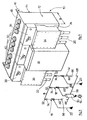
- a prefabricated electrical panel 10 for a medium-voltage substation for distribution or transformation comprises a shielded cell with total insulation including the tank 12 metal is at the potential of the earth.
- the sealed tank 12 has a parallelepiped structure and is filled with insulating gas with high dielectric strength, in particular SF 6 at a pressure close to atmospheric pressure.
- Table 10 comprises three three-pole switches 14, 16, 18 with self-blowing arranged inside the tank 12 for supplying an external transformer 19 from a three-phase loop network.
- the switches 14, 16 form two “incoming” sub-assemblies connected to the network by means of cables 20, 22 associated with cable boxes 24, 26 or with plug-in connectors 28.
- the central switch 18 cooperates with a play fuse circuit breaker 30 housed in an auxiliary compartment 32 to constitute a "flow" sub-assembly and for protecting the transformer 19.
- the cable boxes 24, 26 and the plug-in connectors 28 used for the connection of the sub-assemblies arriving to the network are arranged on the front face 34 outside the sealed tank 12. It is the same for the auxiliary compartment 32 of the fuse circuit breaker 30 which is formed by an elongated vertical well filled with air and attached externally to the tank 12 by being interposed between the two cable boxes 24, 26 (fig 1).
- the nine poles 14 R, 14 S, 14 T; 16 R, 16 S, 16 T; 18 R, 18 S, 18 T of the three self-blowing switches 14 to 18 are all identical, and extend vertically inside the tank 12, being offset transversely from one another by regular intervals to form a single row parallel to the front face (fig. 2).
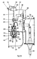
- Each three-pole switch 14, 16, 18 is actuated by an operating mechanism 36, 38, 40 accessible from the front face 34 and disposed outside of the tank 12 respectively above the cable boxes 24, 26 and the compartment. auxiliary 32 with fuses 30 (fig. 1 and 4A).
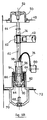
- the operating mechanism 36, 38, 40 is coupled to a transmission crank 42 capable of moving the moving element of the three poles of the associated switch 14, 16, 18 between three stable positions, namely a first service position F and of closing the contacts (fig. 5A), a second intermediate position 0 for opening (fig. 5B) and isolation and a third position T for earthing (fig. 5C).
- the single transverse row of the set of poles 14 R to 18 T makes it possible to use a compact parallelepiped tank 12 whose depth d is reduced relative to the width.
- the rear rear face 44 of the tank 12 is substantially planar and is provided with fixing means 46 for hanging the switchgear 10 on the transformer casing or directly on a wall.
- the horizontal upper face 48 extending perpendicular to the front 34 and rear 44 faces of the tank 12 is capped by nine insulators 50 in the form of bells arranged in a transverse row above the poles 14 R to 18 T, each insulator 50 being equipped with a pad 52 for earthing the corresponding pole. Each pad 52 is connected to the metal tank 12 by a connecting braid 54.
- the bells 50 are made of a transparent insulating material making it possible to view the position of the moving assembly of the switches 14 to 18.
- the position T of setting earth of the sub-assemblies arrival and departure of the table 10 is easily verifiable thanks to the transparency of the bells 50.
- each bell 50 thus fulfills two distinct functions by being arranged in viewing window of the position Grounding and dielectric test isolator.
- the different poles 14 R to 18 T of the three-pole switches are electrically interconnected by a three-phase busbar 58 (fig. 4A) housed in the lower part of the tank 12, extending parallel to the front face 34 in the transverse direction d alignment of the poles.
- the poles 14 R to 18 T of the self-blowing and SF 6 isolation switches are all identical, and only one of them, associated with the switch 14, will be described in detail with reference to FIGS. 4A and 5A. 5C.
- Such a switch with three distinct positions eliminates the need for an auxiliary earthing switch and its control, thereby resulting in a significant reduction in the size of the switchboard.
- each pole of the switch 14 comprises a movable conductive pin 60 coupled by a spreader 62 made of insulating material to the crank 42 of the operating mechanism 36.
- the spreader 62 cooperates with two vertical rods 64 of guide of the sliding spindle 60 during its vertical displacement in alternating translation between the positions F of closing, 0 of opening and T of earthing.
- the conductive pin 60 comprises a first clamp contact 66 cooperating in the closed position F (FIGS. 4A and 5A) with a fixed contact 68 carried by an arch 70 made of insulating material.
- the fixed contact 68 passes through the hoop 70 and is shaped as a connection area for the busbar 58.
- the hoops 70 of all the poles are secured to a horizontal metal rail 72 forming a frame fixed to the internal wall of the tank 12 extending parallel to the busbar 58.
- the pin 60 is provided with a second clamp contact 74 which fits on the pad 52 of the insulator 50 in position T earthing (fig. 5C).
- This ninth contact 74 is advantageously covered with a colored marking means facilitating the visualization of the pin 60 through the transparent insulator 50 when the switch is in position T.
- a braid 76 for connection connects the pin 60 to a terminal external connection 78 secured to a sealed passage 80 exiting perpendicularly through the front face 3d of 1 .. tank 17
- the insulating arch 70 supporting the fixed contact 68 and the busbar 58 carries, above the metal rail 72, a cylindrical extension arranged as a fixed external cylinder 82 with a closable open bottom 84.
- a piston 86 secured to the movable spindle 60 is slidably mounted in the cylinder 82 to form the self-blowing device with a pistonable volume 88 generating compression of the blowing gas when the switch is actuated from the closed position F towards the position intermediate 0 for opening the contacts.
- a convergent nozzle 90 is subject to the piston 86 in order to channel the flow of compressed gas through orifices 92 towards the cutting and extension zone of the arc drawn between the contacts 68, 66.
- table 10 An important advantage of table 10 is to allow from the front face 34 of the tank 12 the connection of cables of different types and extending in several directions. It is noted that all of the crossings 80 for connecting the different poles 14 R to 18 T are aligned on the same row at mid-height of the tank 12 and are therefore easily accessible from the front face 34.
- a three-pole cable box 24 is connected to the corresponding bushings 80 of the switch 14 to form an incoming sub-assembly supplied by the network. The departure of the cables 20 takes place downwards.
- the cable box 24 of the incoming sub-assembly has been replaced by plug-in bent molded connectors 28 of the single-pole or three-pole type.
- the departure of the 20 dry cables is also planned downwards.
- FIG. 4C shows the auxiliary compartment 32 of the fuse circuit breakers 30 comprising upstream connection pads adaptable to the bushings 80 of the central switch 18 to constitute the starting sub-assembly.
- the interior of compartment 32 is filled with air and is closed by a plug 100.
- the departure of the cables 102 from the side of the downstream connection pads of the fuses 30 is provided towards the rear, but could of course be carried out towards the low.
- the metal rail 72 of the pole support chassis also acts as a ground ring inside the tank 12 to avoid any untimely initiation between the contacts of each pole in the 0 isolation position.
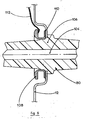
- the crossing 80 for connecting each pole 14 R to 18 T is formed by a high voltage conductor 104 embedded in an insulating body 106 passing through the metal tank 12 at the earth potential.
- a potential screen 108 of conductive or semiconductor material is arranged inside the tank 12 by coaxially surrounding the body 106 and the conductor 104.
- the screen 108 is attached by one of its faces to the internal wall of the tank 12 with the interposition of an insulated seal 110, for example an adhesive.
- the screen 108 cooperates with the conductor 104 and the tank 12 to form a capacitive divider.
- a high voltage capacitor is formed between the straight conductor 104 and the screen 108, and the low voltage capacitor is arranged between the screen 108 and the tank 12 at the level of the insulated joint 110. It suffices to weld a flexible conductor 112 for connection to the screen 108 and to connect this conductor 112 to a voltage presence indicator placed outside the tank 12.
Landscapes
- Engineering & Computer Science (AREA)
- Power Engineering (AREA)
- Gas-Insulated Switchgears (AREA)
- Testing Relating To Insulation (AREA)
Claims (10)
Applications Claiming Priority (2)
| Application Number | Priority Date | Filing Date | Title |
|---|---|---|---|
| FR8112181 | 1981-06-16 | ||
| FR8112181A FR2507835A1 (fr) | 1981-06-16 | 1981-06-16 | Cellule blindee a isolement gazeux pour poste electrique a moyenne tension |
Publications (3)
| Publication Number | Publication Date |
|---|---|
| EP0068951A1 EP0068951A1 (de) | 1983-01-05 |
| EP0068951B1 true EP0068951B1 (de) | 1985-10-02 |
| EP0068951B2 EP0068951B2 (de) | 1988-11-30 |
Family
ID=9259732
Family Applications (1)
| Application Number | Title | Priority Date | Filing Date |
|---|---|---|---|
| EP19820401045 Expired EP0068951B2 (de) | 1981-06-16 | 1982-06-09 | Gasisolierte gekapselte Zelle für elektrische Mittelspannungsanlage |
Country Status (7)
| Country | Link |
|---|---|
| EP (1) | EP0068951B2 (de) |
| JP (1) | JPS5849010A (de) |
| AU (1) | AU561392B2 (de) |
| DE (1) | DE3266661D1 (de) |
| FR (1) | FR2507835A1 (de) |
| IN (1) | IN156601B (de) |
| YU (1) | YU41384B (de) |
Families Citing this family (13)
| Publication number | Priority date | Publication date | Assignee | Title |
|---|---|---|---|---|
| DE3364632D1 (en) * | 1982-04-05 | 1986-08-28 | Y S Securities Ltd | Electrical switchgear |
| FR2532791A1 (fr) * | 1982-09-02 | 1984-03-09 | Alsthom Atlantique | Cellule de distribution a haute tension pour poste de transformation |
| FR2565851B1 (fr) * | 1984-06-14 | 1994-02-11 | Innovations Meca Alimentaires | Tete de separation mecanique destinee notamment au traitement des carcasses broyees et machine qui en est equipee |
| DE3609509A1 (de) * | 1986-03-20 | 1987-09-24 | Behr Industrieanlagen | Elektrischer hochspannungsschalter zum erden insbesondere eines elektrostatischen beschichtungssystems |
| FR2609837B1 (fr) * | 1987-01-19 | 1989-04-14 | Merlin Gerin | Disjoncteur polyphase a autoexpansion equipe d'une chambre de coupure blindee par pole |
| FR2655768B1 (fr) * | 1989-12-13 | 1993-10-08 | Merlin Gerin | Interrupteur tripolaire a haute tension et a isolement gazeux. |
| DE4035472C2 (de) * | 1990-11-08 | 1999-05-06 | Alstom Sachsenwerk Gmbh | Schaltgerät |
| DE4322530A1 (de) * | 1993-07-07 | 1995-01-12 | Driescher Spezialfab Fritz | Gekapselte, isoliergasgefüllte Mittelspannungsschaltzelle |
| FR2725844B1 (fr) | 1994-10-12 | 1996-12-13 | Schneider Electric Sa | Appareillage electrique a haute tension et a isolement gazeux equipe d'un dispositif court-circuiteur d'arc |
| CN112154582B (zh) * | 2018-05-24 | 2023-01-03 | 三菱电机株式会社 | 气体绝缘开关装置 |
| CN108918953B (zh) * | 2018-09-07 | 2024-04-26 | 深圳市南锐电气技术有限公司 | 带电led指示器 |
| FR3150914B1 (fr) * | 2023-07-06 | 2025-06-13 | Appareillages Bobinage Electrique Et Luminaires | Unité de connexion destinée à être utilisée dans un réseau électrique et système de connexion comprenant celle-ci |
| EP4723408A1 (de) * | 2024-10-02 | 2026-04-08 | Hitachi Energy Ltd | Isolatoranordnung für ein hoch- oder mittelspannungsgerät sowie hoch- oder mittelspannungsgerät |
Family Cites Families (6)
| Publication number | Priority date | Publication date | Assignee | Title |
|---|---|---|---|---|
| BE557407A (de) * | 1957-04-01 | |||
| NL120001C (nl) * | 1962-06-13 | 1964-10-15 | Coq Nv | Beschermde schakelaar voor hoge spanning |
| LU43958A1 (de) * | 1963-06-25 | 1964-12-28 | ||
| FR1451507A (fr) * | 1965-07-21 | 1966-01-07 | Comp Generale Electricite | Ensemble avec interrupteur-commutateur pour cellule préfabriquée |
| FR2242794B1 (de) * | 1973-08-30 | 1976-11-19 | Merlin Gerin | |
| DE2924430A1 (de) * | 1979-06-16 | 1980-12-18 | Bbc Brown Boveri & Cie | Metallgekapselte, sf tief 6 -gasisolierte schaltanlage |
-
1981
- 1981-06-16 FR FR8112181A patent/FR2507835A1/fr active Granted
-
1982
- 1982-06-09 EP EP19820401045 patent/EP0068951B2/de not_active Expired
- 1982-06-09 DE DE8282401045T patent/DE3266661D1/de not_active Expired
- 1982-06-14 YU YU129082A patent/YU41384B/xx unknown
- 1982-06-15 JP JP57102943A patent/JPS5849010A/ja active Granted
- 1982-06-15 IN IN688/CAL/82A patent/IN156601B/en unknown
- 1982-06-16 AU AU84918/82A patent/AU561392B2/en not_active Ceased
Also Published As
| Publication number | Publication date |
|---|---|
| JPH0136321B2 (de) | 1989-07-31 |
| IN156601B (de) | 1985-09-14 |
| EP0068951B2 (de) | 1988-11-30 |
| AU561392B2 (en) | 1987-05-07 |
| YU129082A (en) | 1984-12-31 |
| YU41384B (en) | 1987-02-28 |
| JPS5849010A (ja) | 1983-03-23 |
| FR2507835A1 (fr) | 1982-12-17 |
| AU8491882A (en) | 1982-12-23 |
| FR2507835B1 (de) | 1983-10-28 |
| EP0068951A1 (de) | 1983-01-05 |
| DE3266661D1 (en) | 1985-11-07 |
Similar Documents
| Publication | Publication Date | Title |
|---|---|---|
| EP0068951B2 (de) | Gasisolierte gekapselte Zelle für elektrische Mittelspannungsanlage | |
| EP0771057B1 (de) | Mittelspannungsschaltanlage | |
| EP0165184B1 (de) | Metallverkapselte gasisolierte dreiphasige Schaltanlage | |
| EP0277848B1 (de) | Mehrphasenleistungsschalter mit Selbstausdehnung, ausgerüstet mit einer gekapselten Löschkammer je Phase | |
| CH634177A5 (en) | Switching facility for high-voltage electrical current | |
| FR2761823A1 (fr) | Poste de distribution d'energie electrique | |
| EP3001521B1 (de) | Mittelspannungsschutzgerät mit stromzählung | |
| FR2532791A1 (fr) | Cellule de distribution a haute tension pour poste de transformation | |
| EP0017545B1 (de) | Dreiphasentrennschalter für Mittelspannungszelle | |
| EP0348312B1 (de) | Gekapselte Station für ein Hochspannungsnetz | |
| EP0906648B1 (de) | Elektrische schaltzelle mit einer metallischem kasten | |
| FR2525807A1 (fr) | Disjoncteur avec transformateur de courant incorpore | |
| EP0338382A1 (de) | Zelle für gekapselte Mittel oder Hochspannungsstation und Station, die aus solchen Zellen aufgebaut ist | |
| FR2596915A1 (fr) | Disjoncteur electrique a autosoufflage ayant une tenue dielectrique elevee | |
| EP0433183A1 (de) | Dreipoliger gasisolierter Hochspannungsschalter | |
| FR2789798A1 (fr) | Module de disjoncteur auto-sectionneur, moyenne tension et poste de distribution d'energie correspondant | |
| KR101123251B1 (ko) | 에폭시몰드 절연 부하개폐기 | |
| FR2558013A1 (fr) | Armoire de raccordement en derivation d'un poste electrique moyenne tension | |
| EP0002398A1 (de) | Verbesserungen an Stromverteilungszellen | |
| FR2595003A1 (fr) | Appareillage electrique multipolaire a enveloppe commune et a isolement gazeux | |
| JPH0620329B2 (ja) | ガス絶縁開閉装置 | |
| KR101045109B1 (ko) | 고체절연 스위치기어 | |
| FR2518304A2 (fr) | Manchon pour cable a moyenne tension raccorde a un caisson metallique | |
| FR2620564A1 (fr) | Interrupteur de ligne multipolaire a isolement gazeux | |
| FR2471064A1 (fr) | Cellule electrique a disjoncteur sectionnable |
Legal Events
| Date | Code | Title | Description |
|---|---|---|---|
| PUAI | Public reference made under article 153(3) epc to a published international application that has entered the european phase |
Free format text: ORIGINAL CODE: 0009012 |
|
| AK | Designated contracting states |
Designated state(s): BE CH DE GB IT LI NL SE |
|
| 17P | Request for examination filed |
Effective date: 19830707 |
|
| ITF | It: translation for a ep patent filed | ||
| GRAA | (expected) grant |
Free format text: ORIGINAL CODE: 0009210 |
|
| AK | Designated contracting states |
Designated state(s): BE CH DE GB IT LI NL SE |
|
| REF | Corresponds to: |
Ref document number: 3266661 Country of ref document: DE Date of ref document: 19851107 |
|
| PLBI | Opposition filed |
Free format text: ORIGINAL CODE: 0009260 |
|
| 26 | Opposition filed |
Opponent name: SIEMENS AKTIENGESELLSCHAFT, BERLIN UND MUENCHEN Effective date: 19860514 |
|
| NLR1 | Nl: opposition has been filed with the epo |
Opponent name: SIEMENS AKTIENGESELLSCHAFT |
|
| ITF | It: translation for a ep patent filed | ||
| PUAH | Patent maintained in amended form |
Free format text: ORIGINAL CODE: 0009272 |
|
| STAA | Information on the status of an ep patent application or granted ep patent |
Free format text: STATUS: PATENT MAINTAINED AS AMENDED |
|
| 27A | Patent maintained in amended form |
Effective date: 19881130 |
|
| AK | Designated contracting states |
Kind code of ref document: B2 Designated state(s): BE CH DE GB IT LI NL SE |
|
| NLR2 | Nl: decision of opposition | ||
| NLR3 | Nl: receipt of modified translations in the netherlands language after an opposition procedure | ||
| ITTA | It: last paid annual fee | ||
| EAL | Se: european patent in force in sweden |
Ref document number: 82401045.8 |
|
| PGFP | Annual fee paid to national office [announced via postgrant information from national office to epo] |
Ref country code: SE Payment date: 19990414 Year of fee payment: 18 |
|
| PGFP | Annual fee paid to national office [announced via postgrant information from national office to epo] |
Ref country code: GB Payment date: 19990609 Year of fee payment: 18 |
|
| PGFP | Annual fee paid to national office [announced via postgrant information from national office to epo] |
Ref country code: CH Payment date: 19990614 Year of fee payment: 18 |
|
| PGFP | Annual fee paid to national office [announced via postgrant information from national office to epo] |
Ref country code: DE Payment date: 19990617 Year of fee payment: 18 |
|
| PGFP | Annual fee paid to national office [announced via postgrant information from national office to epo] |
Ref country code: NL Payment date: 19990628 Year of fee payment: 18 |
|
| PGFP | Annual fee paid to national office [announced via postgrant information from national office to epo] |
Ref country code: BE Payment date: 19990819 Year of fee payment: 18 |
|
| PG25 | Lapsed in a contracting state [announced via postgrant information from national office to epo] |
Ref country code: GB Free format text: LAPSE BECAUSE OF NON-PAYMENT OF DUE FEES Effective date: 20000609 |
|
| PG25 | Lapsed in a contracting state [announced via postgrant information from national office to epo] |
Ref country code: SE Free format text: LAPSE BECAUSE OF NON-PAYMENT OF DUE FEES Effective date: 20000610 |
|
| PG25 | Lapsed in a contracting state [announced via postgrant information from national office to epo] |
Ref country code: LI Free format text: LAPSE BECAUSE OF NON-PAYMENT OF DUE FEES Effective date: 20000630 Ref country code: CH Free format text: LAPSE BECAUSE OF NON-PAYMENT OF DUE FEES Effective date: 20000630 Ref country code: BE Free format text: LAPSE BECAUSE OF NON-PAYMENT OF DUE FEES Effective date: 20000630 |
|
| BERE | Be: lapsed |
Owner name: MERLIN GERIN Effective date: 20000630 |
|
| PG25 | Lapsed in a contracting state [announced via postgrant information from national office to epo] |
Ref country code: NL Free format text: LAPSE BECAUSE OF NON-PAYMENT OF DUE FEES Effective date: 20010101 |
|
| GBPC | Gb: european patent ceased through non-payment of renewal fee |
Effective date: 20000609 |
|
| REG | Reference to a national code |
Ref country code: CH Ref legal event code: PL |
|
| EUG | Se: european patent has lapsed |
Ref document number: 82401045.8 |
|
| NLV4 | Nl: lapsed or anulled due to non-payment of the annual fee |
Effective date: 20010101 |
|
| PG25 | Lapsed in a contracting state [announced via postgrant information from national office to epo] |
Ref country code: DE Free format text: LAPSE BECAUSE OF NON-PAYMENT OF DUE FEES Effective date: 20010501 |