EP0069099A1 - Verzögerungsvorrichtung zum Rangieren von Eisenbahnwagen - Google Patents
Verzögerungsvorrichtung zum Rangieren von Eisenbahnwagen Download PDFInfo
- Publication number
- EP0069099A1 EP0069099A1 EP82850139A EP82850139A EP0069099A1 EP 0069099 A1 EP0069099 A1 EP 0069099A1 EP 82850139 A EP82850139 A EP 82850139A EP 82850139 A EP82850139 A EP 82850139A EP 0069099 A1 EP0069099 A1 EP 0069099A1
- Authority
- EP
- European Patent Office
- Prior art keywords
- braking
- railway car
- shaft
- car retarder
- retainer
- Prior art date
- Legal status (The legal status is an assumption and is not a legal conclusion. Google has not performed a legal analysis and makes no representation as to the accuracy of the status listed.)
- Granted
Links
- 230000008878 coupling Effects 0.000 claims abstract description 19
- 238000010168 coupling process Methods 0.000 claims abstract description 19
- 238000005859 coupling reaction Methods 0.000 claims abstract description 19
- 238000005096 rolling process Methods 0.000 claims abstract description 5
- 230000000979 retarding effect Effects 0.000 claims description 3
- 230000001133 acceleration Effects 0.000 claims 1
- 238000006073 displacement reaction Methods 0.000 claims 1
- 230000001419 dependent effect Effects 0.000 abstract description 3
- 230000000694 effects Effects 0.000 description 6
- 239000007788 liquid Substances 0.000 description 4
- 238000007689 inspection Methods 0.000 description 2
- 239000000463 material Substances 0.000 description 2
- 238000010521 absorption reaction Methods 0.000 description 1
- 238000006243 chemical reaction Methods 0.000 description 1
- 238000013016 damping Methods 0.000 description 1
- 230000005484 gravity Effects 0.000 description 1
- 230000003137 locomotive effect Effects 0.000 description 1
- 238000005461 lubrication Methods 0.000 description 1
- 238000004519 manufacturing process Methods 0.000 description 1
- 238000012986 modification Methods 0.000 description 1
- 230000004048 modification Effects 0.000 description 1
- 230000007935 neutral effect Effects 0.000 description 1
- 230000000284 resting effect Effects 0.000 description 1
Images

Classifications
-
- B—PERFORMING OPERATIONS; TRANSPORTING
- B61—RAILWAYS
- B61K—AUXILIARY EQUIPMENT SPECIALLY ADAPTED FOR RAILWAYS, NOT OTHERWISE PROVIDED FOR
- B61K7/00—Railway stops fixed to permanent way; Track brakes or retarding apparatus fixed to permanent way; Sand tracks or the like
- B61K7/02—Track brakes or retarding apparatus
Definitions
- the present invention refers to a railway car retarder for shunting purposes and of the type used as one or more units anchored along a railway track, each unit being provided with an actuating member, which when contacted by wheels of passing railway cars will exert a retarding effect on these provided the speed of said wheels exceed an adjustable value pre-set for each retarder unit.
- Braking units of this type are known in several structurally different embodiments.
- a common feature of the embodiments which in recent years have been used ever more is that they are of hydraulic type, at which the passing wheel via a pedal, a ramp or the like is urged to pump a hydraulic liquid in a closed circuit in the braking unit.
- the liquid passes thereby a flow depending throttling device, which means that the work will be big at high flow speeds and neglectably small at low flow speeds.
- Hydraulic systems with the energy absorption here concerned require qualified material and precision manufacture whereby they will also be expensive. It is also difficult to make e.g. inlets for shafts and piston rods thus that they during several years and in severe working environment will be leak-proof.
- the demands for leakproofness and cleanness furthermore mean that inspection and adjustment of the inner components of the brake can not be accomplished on the field but must take place on especial workshops by particularly trained personnel.
- the hydralic brakes furthermore give a certain unintended braking effect even when the cars pass at such a low speed that it is desired that they are not subjected to any braking effect whatsoever.
- the hydraulic brake units are also marred with other problems, which make i desirable with a practically useful solution, which does not utilize hydraulics, e.g. in the form of a simple mechanical friction brake, but development in this direction has been hampered by the fact that the brake force must be so accurately balanced that a maximum braking effect is achieved without therefore risking that the brake will lift a light car wheel from the track.
- a hydraulic pressure can be adjusted very accurately whereas friction coefficient variations at e.g. a disc brake can give considerable variations in the braking ability due to temperature and moisture variations, material wear etcetera.
- a well designed hydraulic brake has consequently a long life span and mainly constant braking characteristics as this brake will get adequate lubrication and is subjected only to a minimum of wear as the braking work is transferred into heat due to flow losses in the liquid and not by mechanical friction.
- mechanical brakes it is on the contrary inevitable that the friction surfaces are subjected to a certain wear, which necessiates a continuous re-adjustment of the positions of the braking surfaces concurrently with the wear.
- the purpose of the invention is to provide a railway car retarder for shunting purposes and of the type used as one or more units anchored along a railway track, each unit being provided with an actuating member, which when contacted by wheels of passing railway cars will exert a retarding effect on these provided the speed of said wheels exceed an adjustable value pre-set for each retarder unit, and the intention is to provide a car retarder with the basic good features of the mechanical friction brake, but which is made in such a manner that it can match the hydraulic brake in the above-mentioned important details, and such a solution has been achived thereby that the actuating member is connected to a pivotable, mainly horizontal shaft, provided with a speed depending freewheel coupling semi-detached to the hub of a braking device in such a manner that the shaft is coupled to the braking device if a car passes in the intended braking direction at a speed exceeding said adjustable value, whereas coupling fails to occur if the car has a lower speed or passes in the opposite direction.
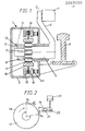
- the railway car retarder 1 is located on the inner side of railway rail 2, and it incorporates an actuating member 3, in the embodiment shown shaped as a lever, which in neutral position is directed mainly straight upwards and which at its upper end is provided with a pedal roller 4 arranged to be hit by a passing, not shown, railway car wheel.
- the actuating member 3 is at its end remote from the pedal roller 4 non-pivotally connected to a mainly horizontal shaft 5, which is pivotably supported in the car retarder housing 6, and which, when the pedal roller 4 is hit by the flange of a passing car wheel, causing the lever 3 to be pushed down to a mainly horizontal position, will make a pivoting of about a quarter of a revolution.
- a speed dependent coupling which resembles to a common freewheel coupling and consists of a hub 7 formed on the shaft, rollers or locking bodies 9 which are guided in a rolling body retainer 8, and an outer sleeve 10 located outside said retainer and being shaped thus that the locking bodies can be wedged between hub and outer sleeve and thereby transfer a moment between them.
- the rotational speed of the shaft is at the beginning of its rotation directly proportional to the speed of the car wheel, and the movement starts instantaneously. It is this movement which is sensed by the speed depending coupling and in the same manner as in a freewheel coupling this transfer of moment can take place when the shaft is pivoted in one direction only.
- a connecting action is achieved when the pedal roller 4 is moved in a direction inwards into the paper.
- roller retainer 8 is rotated a certain, small angle backwards relative to the shaft.
- the coupling catches as a freewheel coupling only if a car passes in the braking direction and has a speed exceeding a certain level. Cars having a lower speed or cars passing in the opposite direction will not cause the coupling to catch.
- the braking part is shown in figure 1 in a simplified embodiment from which is shown that the outer sleeve 10 is rigidly connected to a brake disc 14 provided with brake linings which can be squeezed between two non-rotating discs 15 and 16. This constitutes the main principle for how braking is effected when the speed sensing coupling catches and urges the outer sleeve 10 to take part in the rotation of the shaft.
- Figure 2 thus shows a braking part in the form of a conventional strap brake, which incorporates a brake drum 17 and a brake strap 18 surrounding the drum, which strap via a lever arrangement 19 is held tightened by the power of a pneumatic cylinder 20, which acts upon the brake strap with a force Fa.
- the opposite end of the strap is fixedly attached and it is loaded with a reaction force Fo. Due to the rotational direction of the brake disc and the dimensions given to the brake it is possible to let the braking force be substantially equal to the actuation force Fa of the pneumatic cylinder, whereby a well defined braking power can be achieved even if the friction coefficient varies.
- FIG 3 is schematically shown the actuation principle for the braking part according to the embodiment shown in figure 1, and from this figure it can be seen how the outer sleeve 10 with the associated brake linings 14 is squeezed between the fixed brake disc 15 and the adjustable brake disc 16.
- the actuation power from a pneumatic cylinder (not shown in the figure) or the like is allowed to act tangentially on the adjustable disc 16, which thereby is adjusted with a helical movement.
- the outer sleeve 10 is presupposed to rotate in the opposite direction in relation to the adjustable disc 16. If the pitch of the helical movement is small and the thread friction is neglectably low balance is achieved between the actuation moment and the braking moment, as the friction moment directly counteracts the actuation moment.
- FIG 5 is shown in cross-section and schematically the upper part of the actuating member 3 and particularly the pedal roller 4 thereof.
- the car retarder according to the invention it is achieved that the above mentioned tendency of unintended braking occuring at hydraulic brakes is eliminated, but this can in stead give rise to bounces at impact between car wheel and pedal roller.
- the shaft 3a extending from the pedal arm of the actuating member 3 is provided with a bush 25, which at its outer envelope surface is provided with two parallel and spaced apart annular grooves 26, in each of which is arranged an O-ring 27 of suitable size.
- the pedal roller 4 is then arranged on the outside of the bush 25, and it can be locked to the bush with aid of a stop screw 28 or the like.
- a stop screw 28 or the like In the annular gap space formed between the two O-rings 27, the inner envelope surface of the pedal roller 4 and the outer envelope surface of the bush 25, is introduced a volume of oil filling up said space. Due to this measure the pedal roller will get a sufficient damping effect for eliminating bounces of the above mentioned type without the need of maintaining the unintended braking effect of the hydraulic brake.
- the invention thus provides a railway car retarder, which despite its simple basic structure has properties fully comparable to those of hydraulic braking units, at the same time as certain evident advantages are at hand as compared to these older hydraulic brakes, not least regarding weight, price and possibilities of inspection and service also at the place of use.
- the braking action of the brake is directly dependent of an adjustment force, which can be generated by a pneumatic cylinder.
- an adjustment force which can be generated by a pneumatic cylinder.
Landscapes
- Engineering & Computer Science (AREA)
- Mechanical Engineering (AREA)
- Braking Arrangements (AREA)
- Regulating Braking Force (AREA)
- Stopping Of Electric Motors (AREA)
Priority Applications (1)
| Application Number | Priority Date | Filing Date | Title |
|---|---|---|---|
| AT82850139T ATE16990T1 (de) | 1981-06-22 | 1982-06-21 | Verzoegerungsvorrichtung zum rangieren von eisenbahnwagen. |
Applications Claiming Priority (2)
| Application Number | Priority Date | Filing Date | Title |
|---|---|---|---|
| SE8103889A SE455593B (sv) | 1981-06-22 | 1981-06-22 | Vagnbroms for rangeringsendamal |
| SE8103889 | 1981-06-22 |
Publications (2)
| Publication Number | Publication Date |
|---|---|
| EP0069099A1 true EP0069099A1 (de) | 1983-01-05 |
| EP0069099B1 EP0069099B1 (de) | 1985-12-18 |
Family
ID=20344114
Family Applications (1)
| Application Number | Title | Priority Date | Filing Date |
|---|---|---|---|
| EP82850139A Expired EP0069099B1 (de) | 1981-06-22 | 1982-06-21 | Verzögerungsvorrichtung zum Rangieren von Eisenbahnwagen |
Country Status (4)
| Country | Link |
|---|---|
| EP (1) | EP0069099B1 (de) |
| AT (1) | ATE16990T1 (de) |
| DE (1) | DE3268011D1 (de) |
| SE (1) | SE455593B (de) |
Cited By (3)
| Publication number | Priority date | Publication date | Assignee | Title |
|---|---|---|---|---|
| WO1989010288A1 (en) * | 1988-04-27 | 1989-11-02 | Ibico Svenska Ab | Device for braking wheel-mounted vehicles |
| GB2219565A (en) * | 1988-04-15 | 1989-12-13 | Mid West Conveyor Co | Trolley braking method and apparatus for use with conveyors |
| CN115593461A (zh) * | 2022-10-09 | 2023-01-13 | 徐州迈科思机械科技有限公司(Cn) | 轨道制动装置 |
Families Citing this family (1)
| Publication number | Priority date | Publication date | Assignee | Title |
|---|---|---|---|---|
| RU2477636C1 (ru) * | 2012-03-11 | 2013-03-20 | Государственное бюджетное учреждение здравоохранения Московской области "Московский областной научно-исследовательский клинический институт им. М.Ф. Владимирского" (ГБУЗ МО МОНИКИ им. М.Ф. Владимирского) | Способ лечения острых венозных тромбозов различной локализации на фоне геморрагических осложнений |
Citations (2)
| Publication number | Priority date | Publication date | Assignee | Title |
|---|---|---|---|---|
| US2588798A (en) * | 1948-11-27 | 1952-03-11 | Westinghouse Air Brake Co | Buffer means |
| GB733207A (en) * | 1952-12-10 | 1955-07-06 | Strachan & Henshaw Ltd | Improvements in or relating to devices for retarding the movement of wheeled vehicles |
-
1981
- 1981-06-22 SE SE8103889A patent/SE455593B/sv not_active IP Right Cessation
-
1982
- 1982-06-21 AT AT82850139T patent/ATE16990T1/de active
- 1982-06-21 EP EP82850139A patent/EP0069099B1/de not_active Expired
- 1982-06-21 DE DE8282850139T patent/DE3268011D1/de not_active Expired
Patent Citations (2)
| Publication number | Priority date | Publication date | Assignee | Title |
|---|---|---|---|---|
| US2588798A (en) * | 1948-11-27 | 1952-03-11 | Westinghouse Air Brake Co | Buffer means |
| GB733207A (en) * | 1952-12-10 | 1955-07-06 | Strachan & Henshaw Ltd | Improvements in or relating to devices for retarding the movement of wheeled vehicles |
Cited By (3)
| Publication number | Priority date | Publication date | Assignee | Title |
|---|---|---|---|---|
| GB2219565A (en) * | 1988-04-15 | 1989-12-13 | Mid West Conveyor Co | Trolley braking method and apparatus for use with conveyors |
| WO1989010288A1 (en) * | 1988-04-27 | 1989-11-02 | Ibico Svenska Ab | Device for braking wheel-mounted vehicles |
| CN115593461A (zh) * | 2022-10-09 | 2023-01-13 | 徐州迈科思机械科技有限公司(Cn) | 轨道制动装置 |
Also Published As
| Publication number | Publication date |
|---|---|
| SE8103889L (sv) | 1982-12-23 |
| SE455593B (sv) | 1988-07-25 |
| ATE16990T1 (de) | 1986-01-15 |
| EP0069099B1 (de) | 1985-12-18 |
| DE3268011D1 (en) | 1986-01-30 |
Similar Documents
| Publication | Publication Date | Title |
|---|---|---|
| AU2010202131B2 (en) | Combination cylinder with power-transmitting transmission having variable gear ratio | |
| CN104955688B (zh) | 用于车辆的制动单元和具有这种制动单元的车辆 | |
| US20050247527A1 (en) | Disc brake | |
| US3830343A (en) | Disc brake with adjustable cam operator and thrust distributer | |
| JPS6146241B2 (de) | ||
| US4296897A (en) | Brake torque limiter | |
| JPS61218842A (ja) | 鉄道車両用ブレ−キすきま調節器組立体 | |
| FI56730C (fi) | Lastavhaengigt verkande broms foer transportanordningar | |
| US20150367826A1 (en) | Brake unit for a vehicle and vehicle with a brake unit of this type | |
| EP0069099B1 (de) | Verzögerungsvorrichtung zum Rangieren von Eisenbahnwagen | |
| US4513843A (en) | Railway car retarder for shunting purposes | |
| US20030034212A1 (en) | Force application device for disk brakes | |
| US3534835A (en) | Disk brake | |
| CN1772544B (zh) | 简化的货车用制动系统 | |
| CS197345B2 (en) | Coupling for regulation of the screw press | |
| US2913071A (en) | Packaged brake unit for railway trucks | |
| ITMI20011993A1 (it) | Banco di verifica di avvitatori comprendente un freno a disco sottile | |
| US4556127A (en) | Railway track lubricator | |
| CA2160083C (en) | Empty/load sensor mechanism for controlled vehicle braking | |
| US3557915A (en) | Brake shoe adjusting mechanism for a railway vehicle braking unit | |
| US2258784A (en) | Brake mechanism | |
| RU2174478C2 (ru) | Регулятор тормозных рычажных передач железнодорожного транспортного средства | |
| GB1073829A (en) | Disc brakes | |
| JPS62187642A (ja) | ブレ−キ装置 | |
| ES2634892T3 (es) | Unidad de frenado para un vehículo y vehículo con una unidad de frenado de este tipo |
Legal Events
| Date | Code | Title | Description |
|---|---|---|---|
| PUAI | Public reference made under article 153(3) epc to a published international application that has entered the european phase |
Free format text: ORIGINAL CODE: 0009012 |
|
| AK | Designated contracting states |
Designated state(s): AT CH DE FR GB IT LI |
|
| 17P | Request for examination filed |
Effective date: 19830701 |
|
| ITF | It: translation for a ep patent filed | ||
| GRAA | (expected) grant |
Free format text: ORIGINAL CODE: 0009210 |
|
| AK | Designated contracting states |
Designated state(s): AT CH DE FR GB IT LI |
|
| REF | Corresponds to: |
Ref document number: 16990 Country of ref document: AT Date of ref document: 19860115 Kind code of ref document: T |
|
| REF | Corresponds to: |
Ref document number: 3268011 Country of ref document: DE Date of ref document: 19860130 |
|
| ET | Fr: translation filed | ||
| PGFP | Annual fee paid to national office [announced via postgrant information from national office to epo] |
Ref country code: AT Payment date: 19860616 Year of fee payment: 5 |
|
| PLBE | No opposition filed within time limit |
Free format text: ORIGINAL CODE: 0009261 |
|
| STAA | Information on the status of an ep patent application or granted ep patent |
Free format text: STATUS: NO OPPOSITION FILED WITHIN TIME LIMIT |
|
| 26N | No opposition filed | ||
| PG25 | Lapsed in a contracting state [announced via postgrant information from national office to epo] |
Ref country code: GB Effective date: 19890621 Ref country code: AT Effective date: 19890621 |
|
| PG25 | Lapsed in a contracting state [announced via postgrant information from national office to epo] |
Ref country code: LI Effective date: 19890630 Ref country code: CH Effective date: 19890630 |
|
| GBPC | Gb: european patent ceased through non-payment of renewal fee | ||
| PG25 | Lapsed in a contracting state [announced via postgrant information from national office to epo] |
Ref country code: FR Free format text: LAPSE BECAUSE OF NON-PAYMENT OF DUE FEES Effective date: 19900228 |
|
| REG | Reference to a national code |
Ref country code: CH Ref legal event code: PL |
|
| PG25 | Lapsed in a contracting state [announced via postgrant information from national office to epo] |
Ref country code: DE Effective date: 19900301 |
|
| REG | Reference to a national code |
Ref country code: FR Ref legal event code: ST |