EP0069646A2 - Dispositif d'ajustage verrouillable pour cables - Google Patents
Dispositif d'ajustage verrouillable pour cables Download PDFInfo
- Publication number
- EP0069646A2 EP0069646A2 EP82401189A EP82401189A EP0069646A2 EP 0069646 A2 EP0069646 A2 EP 0069646A2 EP 82401189 A EP82401189 A EP 82401189A EP 82401189 A EP82401189 A EP 82401189A EP 0069646 A2 EP0069646 A2 EP 0069646A2
- Authority
- EP
- European Patent Office
- Prior art keywords
- locking device
- elongate member
- parts
- opening
- angular position
- Prior art date
- Legal status (The legal status is an assumption and is not a legal conclusion. Google has not performed a legal analysis and makes no representation as to the accuracy of the status listed.)
- Ceased
Links
Images
Classifications
-
- F—MECHANICAL ENGINEERING; LIGHTING; HEATING; WEAPONS; BLASTING
- F16—ENGINEERING ELEMENTS AND UNITS; GENERAL MEASURES FOR PRODUCING AND MAINTAINING EFFECTIVE FUNCTIONING OF MACHINES OR INSTALLATIONS; THERMAL INSULATION IN GENERAL
- F16C—SHAFTS; FLEXIBLE SHAFTS; ELEMENTS OR CRANKSHAFT MECHANISMS; ROTARY BODIES OTHER THAN GEARING ELEMENTS; BEARINGS
- F16C1/00—Flexible shafts; Mechanical means for transmitting movement in a flexible sheathing
- F16C1/10—Means for transmitting linear movement in a flexible sheathing, e.g. "Bowden-mechanisms"
- F16C1/22—Adjusting; Compensating length
- F16C1/226—Adjusting; Compensating length by adjusting the effective length of the sheathing
-
- F—MECHANICAL ENGINEERING; LIGHTING; HEATING; WEAPONS; BLASTING
- F16—ENGINEERING ELEMENTS AND UNITS; GENERAL MEASURES FOR PRODUCING AND MAINTAINING EFFECTIVE FUNCTIONING OF MACHINES OR INSTALLATIONS; THERMAL INSULATION IN GENERAL
- F16C—SHAFTS; FLEXIBLE SHAFTS; ELEMENTS OR CRANKSHAFT MECHANISMS; ROTARY BODIES OTHER THAN GEARING ELEMENTS; BEARINGS
- F16C1/00—Flexible shafts; Mechanical means for transmitting movement in a flexible sheathing
- F16C1/10—Means for transmitting linear movement in a flexible sheathing, e.g. "Bowden-mechanisms"
- F16C1/102—Arrangements to mount end fittings of the sheathings to support walls or brackets
- F16C1/105—Arrangements to mount end fittings of the sheathings to support walls or brackets to a slot in the bracket
-
- F—MECHANICAL ENGINEERING; LIGHTING; HEATING; WEAPONS; BLASTING
- F16—ENGINEERING ELEMENTS AND UNITS; GENERAL MEASURES FOR PRODUCING AND MAINTAINING EFFECTIVE FUNCTIONING OF MACHINES OR INSTALLATIONS; THERMAL INSULATION IN GENERAL
- F16C—SHAFTS; FLEXIBLE SHAFTS; ELEMENTS OR CRANKSHAFT MECHANISMS; ROTARY BODIES OTHER THAN GEARING ELEMENTS; BEARINGS
- F16C1/00—Flexible shafts; Mechanical means for transmitting movement in a flexible sheathing
- F16C1/26—Construction of guiding-sheathings or guiding-tubes
- F16C1/262—End fittings; Attachment thereof to the sheathing or tube
-
- F—MECHANICAL ENGINEERING; LIGHTING; HEATING; WEAPONS; BLASTING
- F16—ENGINEERING ELEMENTS AND UNITS; GENERAL MEASURES FOR PRODUCING AND MAINTAINING EFFECTIVE FUNCTIONING OF MACHINES OR INSTALLATIONS; THERMAL INSULATION IN GENERAL
- F16G—BELTS, CABLES, OR ROPES, PREDOMINANTLY USED FOR DRIVING PURPOSES; CHAINS; FITTINGS PREDOMINANTLY USED THEREFOR
- F16G11/00—Means for fastening cables or ropes to one another or to other objects; Caps or sleeves for fixing on cables or ropes
-
- F—MECHANICAL ENGINEERING; LIGHTING; HEATING; WEAPONS; BLASTING
- F16—ENGINEERING ELEMENTS AND UNITS; GENERAL MEASURES FOR PRODUCING AND MAINTAINING EFFECTIVE FUNCTIONING OF MACHINES OR INSTALLATIONS; THERMAL INSULATION IN GENERAL
- F16B—DEVICES FOR FASTENING OR SECURING CONSTRUCTIONAL ELEMENTS OR MACHINE PARTS TOGETHER, e.g. NAILS, BOLTS, CIRCLIPS, CLAMPS, CLIPS OR WEDGES; JOINTS OR JOINTING
- F16B2200/00—Constructional details of connections not covered for in other groups of this subclass
- F16B2200/69—Redundant disconnection blocking means
- F16B2200/73—Cam locks or thread locks
-
- F—MECHANICAL ENGINEERING; LIGHTING; HEATING; WEAPONS; BLASTING
- F16—ENGINEERING ELEMENTS AND UNITS; GENERAL MEASURES FOR PRODUCING AND MAINTAINING EFFECTIVE FUNCTIONING OF MACHINES OR INSTALLATIONS; THERMAL INSULATION IN GENERAL
- F16C—SHAFTS; FLEXIBLE SHAFTS; ELEMENTS OR CRANKSHAFT MECHANISMS; ROTARY BODIES OTHER THAN GEARING ELEMENTS; BEARINGS
- F16C2326/00—Articles relating to transporting
- F16C2326/20—Land vehicles
- F16C2326/28—Bicycle propulsion, e.g. crankshaft and its support
-
- F—MECHANICAL ENGINEERING; LIGHTING; HEATING; WEAPONS; BLASTING
- F16—ENGINEERING ELEMENTS AND UNITS; GENERAL MEASURES FOR PRODUCING AND MAINTAINING EFFECTIVE FUNCTIONING OF MACHINES OR INSTALLATIONS; THERMAL INSULATION IN GENERAL
- F16C—SHAFTS; FLEXIBLE SHAFTS; ELEMENTS OR CRANKSHAFT MECHANISMS; ROTARY BODIES OTHER THAN GEARING ELEMENTS; BEARINGS
- F16C2361/00—Apparatus or articles in engineering in general
- F16C2361/43—Clutches, e.g. disengaging bearing
-
- Y—GENERAL TAGGING OF NEW TECHNOLOGICAL DEVELOPMENTS; GENERAL TAGGING OF CROSS-SECTIONAL TECHNOLOGIES SPANNING OVER SEVERAL SECTIONS OF THE IPC; TECHNICAL SUBJECTS COVERED BY FORMER USPC CROSS-REFERENCE ART COLLECTIONS [XRACs] AND DIGESTS
- Y10—TECHNICAL SUBJECTS COVERED BY FORMER USPC
- Y10T—TECHNICAL SUBJECTS COVERED BY FORMER US CLASSIFICATION
- Y10T403/00—Joints and connections
- Y10T403/29—Rotarily connected, differentially translatable members, e.g., turn-buckle, etc.
- Y10T403/295—Rotarily connected, differentially translatable members, e.g., turn-buckle, etc. having locking means
-
- Y—GENERAL TAGGING OF NEW TECHNOLOGICAL DEVELOPMENTS; GENERAL TAGGING OF CROSS-SECTIONAL TECHNOLOGIES SPANNING OVER SEVERAL SECTIONS OF THE IPC; TECHNICAL SUBJECTS COVERED BY FORMER USPC CROSS-REFERENCE ART COLLECTIONS [XRACs] AND DIGESTS
- Y10—TECHNICAL SUBJECTS COVERED BY FORMER USPC
- Y10T—TECHNICAL SUBJECTS COVERED BY FORMER US CLASSIFICATION
- Y10T74/00—Machine element or mechanism
- Y10T74/20—Control lever and linkage systems
- Y10T74/20396—Hand operated
- Y10T74/20402—Flexible transmitter [e.g., Bowden cable]
- Y10T74/20408—Constant tension sustaining
Definitions
- This invention relates to a locking device for an elongate member, such as a cable assembly in a vehicle.
- cable assemblies are transmission cable assemblies and clutch cable assemblies.
- the end of the cable is usually adjusted during assembly by means of friction or by a nut and bolt assembly to rigidly couple the end of the cable with either a shift lever or a transmission lever. Because of vehicle vibration and friction slippage, it is possible for these types of one shot adjusters or locking devices to work loose and introduce undesirable slack into the cable assembly.
- an essential object of the present invention to provide a locking device for such cable assemblies which is simple and inexpensive to manufacture while performing a most reliable locking function.
- the locking device comprises at least two cooperating parts slidably carried on the elongate member, namely a first part having an opening through which the elongate member extends so as to permit axial relative movement while precluding angular relative movement therebetween, and a second part having an opening through which the elongate member extends so as to permit axial relative movement therebetween when said second part occupies a first angular position and to preclude said axial relative movement when said second part is rotated to a second angular position, means for holding said parts in a substantially fixed axial relationship with respect to each other, means for holding said second part in either its first or second angular position with respect to said first part and elongate at least member, and means for releasably securing/one of said parts to a fixed support.
- the elongate member includes a the substantially triangular cross section with/edges of the triangular cross section defining gripping surfaces and the remaining of the triangular cross section forming sliding surfaces between said edges, the opening in the first part is then of the triangular shape to permit free axial movement thereof along said triangular cross section, and the opening in the second part then includes sets of teeth adapted to mesh with said gripping surfaces when said second part is rotated to its second angular position, said sets of teeth being separated by smooth surfaces permitting said second part to slide axially along said edges when the second part occupies its first angular position.
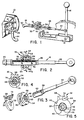
- a transmission generally indicated at 10 is provided withthe-usual settings, such as drive, reverse, neutral, park, etc.
- a lever 12 is operatively connected to the gears of the ' transmission to control the setting therefore.
- a shifter 14 is provided to remotely select the setting for the transmission.
- a cable assembly 16 connects the shifter to the transmission and a support 18 mounts the shifter on the vehicle.
- the cable assembly 16 comprises an elongate member such as a sheath or conduit 20 with a longitudinally extending bore for movably receiving a cable 22.
- One end 24 of the sheath adjacent the transmission is fixed to a bracket 26 and the end of the cable 22 at the one end 24 is connected to the lever such that movement of the cable 22 within the conduit 20 changes the setting for the lever and gears of the transmission.
- the cable 22 extends from the other end 28 of the conduit 20 to connect with the shifter 14.
- the other end 28 of the conduit 20 supports a locking device 30 constructed in accordance with the present invention and adapted to fix the end 28 of the conduit 20 to the support 18 after the cable assembly is adjusted tb index the transmission 10 and the shifter 14 to the same settings.
- the locking device 30 comprises a first part 32 and a second part 34, preferably made from a light weight plastic material.
- the first part 32 forms a triangular opening 36 which substantially matches the cross sectional dimension of a rigid extension 38 swaged to the conduit 20 and considered to be a part thereof.
- the extension 38 also defines teeth 40 at three edges of the triangle and flat surfaces 42 separate the teeth from each other.
- the flat surfaces 42 slidably engage the wall of the triangular opening 36 so that the first part 32 can move longitudinally on the extension 38 but cannot rotate relative thereto, when the extension extends into the opening 36.
- the second part 34 also forms an opening 46 with three portions of teeth 48 and threee portions of smooth surfaces 50.
- the teeth 48 are capable of meshing with the teeth 40 on the extension 38 and the smooth surfaces 50 form a diameter large enough to permit the triangular extension to freely rotate and slide within the opening 46 relative to the smooth surfaces 50.
- the teeth 48 and 40 are engaged, the second part is prevented from moving longitudinally relative to the extension 38, however, when the teeth 40 are aligned with the surfaces 50, the second part 34 is free to move longitudinally on the extension 38.
- the second part forms an annular recess 52 between a pair of radial flanges 54 and 56.
- the flange 56 includes a reduced diameter portion 58 with a pair of grooves 62 and 64.
- the first part 32 includes an axially extending flange 68 overlaying the radial flange 54 and forming a tab 70 and a finger 72.
- the tab 70 extends into the recess 52 and the finger 72 fits'into the groove 62 or 64 when the parts 32 and 34 are carried on the extension.
- the flange 68 is resiliently biased into either groove 62 or 64 so that the finger remains in the groove until manual removal by rotating part 34 relative to part 32.
- the first part 32 is attached to the second part 34 so that the tab 70 is disposed in the recess 52 and the finger 72 is disposed in the groove 62.
- the coupled parts are fitted on the extension 38 with the teeth 48 of second part 34 aligned with the flat surfaces 42 on extension 38. Consequently, the parts will freely move axially on the extension.
- the cable 22 is connected to the lever 12 and the shifter 14.
- the shifter 14 and the transmission are indexed to the same setting and the locking device 30 is moved axially on the extension 38 to align the recess 52 with the slot 76.
- the locking device is fitted through the slot 76 and into the opening 78.
- the arcuate width of flange 68 is equal to or less than the width of the slot 76 so that the flange fits: into the slot 76.
- the second part 34 is rotated counter clockwise to the position shown in Figures 4 and 5, viewed from the shifter 14, so thatbthe finger 72 is fitted into groove 64 to prevent rotation between the parts.
- the reduced diameter section 74 is rotated out of alignment with the slot 76 so that the second Dart is coupled to the support to prevent the second part from withdrawing from the slot 76 and opening 78, thereby preventing separation between the locking device 30 and the support.
- the teeth 48 on the second part 34 are engaged with the teeth 40 on the extension so that the second part prevents axial movement between the extension 38 and the support 18. Any slight angular movement of the extension 38 is accompanied by the same angular movement of parts 32 and 34 as the part 32 rotates with the extension 38 because of its contoured opening 36 to also rotate the part 34 with the extension. Consequently, the teeth 48 remains fully engaged with the teeth 40 regardless of a slight, rotational movement for the extension 38.
- locking device 30 Many variations to the locking device 30 are feasible by one skilled in the art. For example, it is possible to engage the first part 32 with the support 18 rather than engage the second part therewith. Also, second part 34 could be provided with a flexible finger and the first part could be provided with grooves for receiving the flexible finger. These variations as well as others which are feasible by one skilled in the art are intended to be within the scope of the present invention.
Landscapes
- Engineering & Computer Science (AREA)
- General Engineering & Computer Science (AREA)
- Mechanical Engineering (AREA)
- Health & Medical Sciences (AREA)
- Oral & Maxillofacial Surgery (AREA)
- Flexible Shafts (AREA)
- Mechanical Operated Clutches (AREA)
- Mechanical Control Devices (AREA)
Applications Claiming Priority (2)
| Application Number | Priority Date | Filing Date | Title |
|---|---|---|---|
| US06/280,751 US4418583A (en) | 1981-07-06 | 1981-07-06 | Locking device |
| US280751 | 1981-07-06 |
Publications (2)
| Publication Number | Publication Date |
|---|---|
| EP0069646A2 true EP0069646A2 (fr) | 1983-01-12 |
| EP0069646A3 EP0069646A3 (fr) | 1985-04-17 |
Family
ID=23074473
Family Applications (1)
| Application Number | Title | Priority Date | Filing Date |
|---|---|---|---|
| EP82401189A Ceased EP0069646A3 (fr) | 1981-07-06 | 1982-06-28 | Dispositif d'ajustage verrouillable pour cables |
Country Status (7)
| Country | Link |
|---|---|
| US (1) | US4418583A (fr) |
| EP (1) | EP0069646A3 (fr) |
| JP (1) | JPS5817211A (fr) |
| AU (1) | AU546669B2 (fr) |
| CA (1) | CA1181665A (fr) |
| ES (1) | ES276078Y (fr) |
| MX (1) | MX151453A (fr) |
Cited By (3)
| Publication number | Priority date | Publication date | Assignee | Title |
|---|---|---|---|---|
| GB2203511A (en) * | 1987-04-03 | 1988-10-19 | Morse Controls | Bowden mechanism |
| EP0648947A1 (fr) * | 1993-09-16 | 1995-04-19 | Fico Flex, S.A. | Dispositif de commande à distance pour transmettre des mouvements |
| CN103026080A (zh) * | 2010-07-19 | 2013-04-03 | 古斯塔夫.克劳克有限责任公司 | 螺母以及螺栓件与螺母的组合 |
Families Citing this family (26)
| Publication number | Priority date | Publication date | Assignee | Title |
|---|---|---|---|---|
| US4476673A (en) * | 1983-03-11 | 1984-10-16 | Brown Ronald T | Shackle pin locking construction |
| US4841806A (en) * | 1985-09-13 | 1989-06-27 | Teleflex Incorporated | Self-adjust mini increment |
| US4688445A (en) * | 1986-04-21 | 1987-08-25 | Teleflex Incorporated | Remote control balanced adjust system |
| US4778194A (en) * | 1987-07-13 | 1988-10-18 | J. I. Case Company | Tractor hitch and adjustable arm |
| US4781507A (en) * | 1987-08-13 | 1988-11-01 | Duenas Oswaldo A | Quick acting threaded fastener assembly |
| US4798100A (en) * | 1987-09-18 | 1989-01-17 | Babcock Industries Inc. | Automatic adjustment device for cable control systems |
| JPH0262415A (ja) * | 1988-08-24 | 1990-03-02 | Nippon Cable Syst Inc | コントロールケーブルの取付位置調整装置 |
| US5318570A (en) * | 1989-01-31 | 1994-06-07 | Advanced Osseous Technologies, Inc. | Ultrasonic tool |
| US5382251A (en) * | 1989-01-31 | 1995-01-17 | Biomet, Inc. | Plug pulling method |
| US5324297A (en) * | 1989-01-31 | 1994-06-28 | Advanced Osseous Technologies, Inc. | Ultrasonic tool connector |
| JPH087167Y2 (ja) * | 1990-04-17 | 1996-03-04 | トヨタ車体株式会社 | ワイヤー式オートマチックトランスミッションインジケータ |
| US5156064A (en) * | 1991-05-21 | 1992-10-20 | Handy & Harman Automotive Group, Inc. | Cable length adjustment device |
| US5222411A (en) * | 1991-05-21 | 1993-06-29 | Handy & Harmon Automotive Group | Miniature core adjust device |
| US5174677A (en) * | 1991-08-30 | 1992-12-29 | The United States Of America As Represented By The Department Of The Army | Main rotor pitch control rod assembly with passive locking feature |
| US5178034A (en) * | 1992-03-02 | 1993-01-12 | Teleflex Incorporated | Automatic adjust assembly with release pin |
| US5328242A (en) * | 1992-03-18 | 1994-07-12 | Steelcase Inc. | Chair with back lock |
| US5577807A (en) * | 1994-06-09 | 1996-11-26 | Steelcase Inc. | Adjustable chair actuator |
| US7146875B2 (en) * | 2003-01-08 | 2006-12-12 | Dura Global Technologies, Inc. | Locking device for cable assembly |
| US20050220569A1 (en) * | 2004-04-01 | 2005-10-06 | Joseph Dryer | Latching quick-connect connector |
| BRPI0403739A (pt) * | 2004-08-25 | 2006-05-02 | Paolo Paparoni | dispositivo de fixação de terminais de cabos de comando |
| US20070223994A1 (en) * | 2004-09-13 | 2007-09-27 | Murray Cohen | Integrated locking device |
| US20060236804A1 (en) * | 2005-04-26 | 2006-10-26 | Ruhlander Gregory P | Shifter base with integrated receptacle for cable adjust assembly |
| DE102015113822A1 (de) * | 2015-08-20 | 2017-02-23 | Gako International Gmbh | Apotheken-Rezepturherstellungs-Kruken-Deckel, Apotheken-Rezepturherstellungs-Kruken-Boden, Apotheken-Rezepturherstellungs-Kruken-Adapter, Apotheken-Rezepturherstellungs-Kruke damit, Apotheken-Rezepturherstellungs-Vorrichtungs-Hubarm sowie Apotheken-Rezepturherstellungs-Vorrichtung damit |
| KR102554940B1 (ko) * | 2018-04-12 | 2023-07-11 | 현대자동차주식회사 | 차량용 변속레버의 도난방지 장치 |
| KR102692280B1 (ko) * | 2019-03-25 | 2024-08-05 | 현대자동차주식회사 | 차량 도난 방지 장치 |
| US11828326B2 (en) * | 2019-06-26 | 2023-11-28 | Ålö AB | Control system using a control cable, an adapter element for such a system, and a control cable having such an adapter element |
Family Cites Families (17)
| Publication number | Priority date | Publication date | Assignee | Title |
|---|---|---|---|---|
| NL286968A (fr) * | 1900-01-01 | |||
| US1510492A (en) * | 1922-03-25 | 1924-10-07 | Louis G Caron | Nut |
| FR555656A (fr) * | 1922-09-04 | 1923-07-04 | Système vis et écrou à serrage rapide | |
| US2464133A (en) * | 1947-02-19 | 1949-03-08 | William B Herbert | Jig nut |
| US2742073A (en) * | 1952-06-20 | 1956-04-17 | Ernest D Iannetti | Quick attachable nut and bolt assembly |
| US2828662A (en) * | 1954-08-13 | 1958-04-01 | John A Antal | Quick disconnect fastener means having circumferentially movable thread segments |
| US3496800A (en) * | 1968-08-02 | 1970-02-24 | Gen Motors Corp | Self-locking tie rod adjuster |
| US3572159A (en) * | 1969-06-12 | 1971-03-23 | Teleflex Inc | Motion transmitting remote control assembly |
| US3708145A (en) * | 1971-11-09 | 1973-01-02 | Illinois Tool Works | End connector grommet assembly |
| CA1014454A (en) * | 1974-10-15 | 1977-07-26 | Alton M. Andrews | Quick fastening screw device |
| US4048897A (en) * | 1976-05-10 | 1977-09-20 | Price Jr Ellie Edward | Laterally engagable and releasable nut assembly |
| JPS55110509A (en) * | 1979-02-19 | 1980-08-26 | Matsushita Electric Works Ltd | Shelf |
| US4334438A (en) * | 1979-03-09 | 1982-06-15 | Nissan Motor Company, Limited | Clearance adjusting mechanism |
| JPS5843612B2 (ja) * | 1979-07-16 | 1983-09-28 | 日産自動車株式会社 | クリアランス調整装置 |
| US4274754A (en) * | 1979-10-31 | 1981-06-23 | Grumman Aerospace Corporation | Double locking device |
| ES267293Y (es) * | 1980-05-20 | 1983-09-16 | "aparato de cable de control". | |
| US4355920A (en) * | 1980-10-23 | 1982-10-26 | Incom International Inc. | Clamp-to-bulkhead adapters for push pull cable end fittings |
-
1981
- 1981-07-06 US US06/280,751 patent/US4418583A/en not_active Expired - Fee Related
-
1982
- 1982-05-12 CA CA000402800A patent/CA1181665A/fr not_active Expired
- 1982-06-22 AU AU85093/82A patent/AU546669B2/en not_active Ceased
- 1982-06-28 EP EP82401189A patent/EP0069646A3/fr not_active Ceased
- 1982-07-05 MX MX193458A patent/MX151453A/es unknown
- 1982-07-06 ES ES1982276078U patent/ES276078Y/es not_active Expired
- 1982-07-06 JP JP57116306A patent/JPS5817211A/ja active Pending
Cited By (7)
| Publication number | Priority date | Publication date | Assignee | Title |
|---|---|---|---|---|
| GB2203511A (en) * | 1987-04-03 | 1988-10-19 | Morse Controls | Bowden mechanism |
| EP0285299A3 (en) * | 1987-04-03 | 1989-03-08 | Morse Controls Limited | Remote control mechanisms |
| US4887481A (en) * | 1987-04-03 | 1989-12-19 | Morse Controls Limited | Remote control mechanisms |
| GB2203511B (en) * | 1987-04-03 | 1991-01-02 | Morse Controls | Remote control mechanisms |
| EP0648947A1 (fr) * | 1993-09-16 | 1995-04-19 | Fico Flex, S.A. | Dispositif de commande à distance pour transmettre des mouvements |
| CN103026080A (zh) * | 2010-07-19 | 2013-04-03 | 古斯塔夫.克劳克有限责任公司 | 螺母以及螺栓件与螺母的组合 |
| CN103026080B (zh) * | 2010-07-19 | 2015-09-09 | 古斯塔夫.克劳克有限责任公司 | 螺母以及螺栓件与螺母的组合 |
Also Published As
| Publication number | Publication date |
|---|---|
| AU8509382A (en) | 1983-01-13 |
| AU546669B2 (en) | 1985-09-12 |
| ES276078U (es) | 1984-04-01 |
| CA1181665A (fr) | 1985-01-29 |
| EP0069646A3 (fr) | 1985-04-17 |
| JPS5817211A (ja) | 1983-02-01 |
| US4418583A (en) | 1983-12-06 |
| ES276078Y (es) | 1984-11-16 |
| MX151453A (es) | 1984-11-26 |
Similar Documents
| Publication | Publication Date | Title |
|---|---|---|
| EP0069646A2 (fr) | Dispositif d'ajustage verrouillable pour cables | |
| EP0170107B2 (fr) | Unité de commande | |
| EP0727020B1 (fr) | Selecteur pour transmission de vehicule | |
| US4936161A (en) | Cable length adjuster with push and lock attachment | |
| DE69515525T2 (de) | Fahrzeugspiegelverstellgetriebe | |
| US5235866A (en) | Rotary temperature control device | |
| US4192196A (en) | Blocked change gear transmission and improved blocker and jaw clutch assembly therefor | |
| US4813214A (en) | Radial throttle control | |
| DE3003076C2 (de) | Schalteinrichtung für ein Fahrzeuggetriebe | |
| US4307624A (en) | Transmission gear selector arm and sleeves for shifting forks | |
| DE69207131T2 (de) | Steuerungssystem für automatisches Fahrzeuggetriebe | |
| DE60303596T2 (de) | Anzeigemechanismus einer fahrradgangschaltung | |
| GB9418618D0 (en) | Arrangement for controlling the gear change of an automatically shifting gear-change transmission of a motor vehicle | |
| US4727765A (en) | Shift mechanism for manual transmission | |
| DE3445519C2 (fr) | ||
| KR910004601B1 (ko) | 자동차용 수동변속기의 후진변속 제한장치 | |
| EP2514662A1 (fr) | Poignée tournante avec extrémité encliquetable | |
| EP0061216B1 (fr) | Arrangement pour régler la valeur d'un composant électrique | |
| CA2031359A1 (fr) | Dispositif de reluire d'album de photos | |
| AU2019202409B2 (en) | A sequential shift gearbox converter assembly | |
| DE10041875B4 (de) | Bedienteil | |
| US3724281A (en) | Vernier control knob | |
| US6766706B2 (en) | Control lever assembly | |
| DE102014106329A1 (de) | Fahrpedal | |
| US4838197A (en) | Gearshift indicator cable mounting clip |
Legal Events
| Date | Code | Title | Description |
|---|---|---|---|
| PUAI | Public reference made under article 153(3) epc to a published international application that has entered the european phase |
Free format text: ORIGINAL CODE: 0009012 |
|
| 17P | Request for examination filed |
Effective date: 19820705 |
|
| AK | Designated contracting states |
Designated state(s): DE FR GB IT |
|
| PUAL | Search report despatched |
Free format text: ORIGINAL CODE: 0009013 |
|
| AK | Designated contracting states |
Designated state(s): DE FR GB IT |
|
| 17Q | First examination report despatched |
Effective date: 19860326 |
|
| RAP1 | Party data changed (applicant data changed or rights of an application transferred) |
Owner name: ALLIED CORPORATION |
|
| STAA | Information on the status of an ep patent application or granted ep patent |
Free format text: STATUS: THE APPLICATION HAS BEEN REFUSED |
|
| 18R | Application refused |
Effective date: 19870816 |
|
| RIN1 | Information on inventor provided before grant (corrected) |
Inventor name: TAIG, ALISTAIR GORDON |