EP0069826A2 - Dispositif d'ajustage et de contrôle d'une position angulaire prédéterminée d'un corps de rotation - Google Patents
Dispositif d'ajustage et de contrôle d'une position angulaire prédéterminée d'un corps de rotation Download PDFInfo
- Publication number
- EP0069826A2 EP0069826A2 EP82102591A EP82102591A EP0069826A2 EP 0069826 A2 EP0069826 A2 EP 0069826A2 EP 82102591 A EP82102591 A EP 82102591A EP 82102591 A EP82102591 A EP 82102591A EP 0069826 A2 EP0069826 A2 EP 0069826A2
- Authority
- EP
- European Patent Office
- Prior art keywords
- contact
- encoder
- rotational position
- housing
- angle encoder
- Prior art date
- Legal status (The legal status is an assumption and is not a legal conclusion. Google has not performed a legal analysis and makes no representation as to the accuracy of the status listed.)
- Granted
Links
Images
Classifications
-
- B—PERFORMING OPERATIONS; TRANSPORTING
- B23—MACHINE TOOLS; METAL-WORKING NOT OTHERWISE PROVIDED FOR
- B23Q—DETAILS, COMPONENTS, OR ACCESSORIES FOR MACHINE TOOLS, e.g. ARRANGEMENTS FOR COPYING OR CONTROLLING; MACHINE TOOLS IN GENERAL CHARACTERISED BY THE CONSTRUCTION OF PARTICULAR DETAILS OR COMPONENTS; COMBINATIONS OR ASSOCIATIONS OF METAL-WORKING MACHINES, NOT DIRECTED TO A PARTICULAR RESULT
- B23Q16/00—Equipment for precise positioning of tool or work into particular locations not otherwise provided for
- B23Q16/02—Indexing equipment
- B23Q16/04—Indexing equipment having intermediate members, e.g. pawls, for locking the relatively movable parts in the indexed position
-
- G—PHYSICS
- G01—MEASURING; TESTING
- G01B—MEASURING LENGTH, THICKNESS OR SIMILAR LINEAR DIMENSIONS; MEASURING ANGLES; MEASURING AREAS; MEASURING IRREGULARITIES OF SURFACES OR CONTOURS
- G01B7/00—Measuring arrangements characterised by the use of electric or magnetic techniques
- G01B7/30—Measuring arrangements characterised by the use of electric or magnetic techniques for measuring angles or tapers; for testing the alignment of axes
-
- G—PHYSICS
- G01—MEASURING; TESTING
- G01D—MEASURING NOT SPECIALLY ADAPTED FOR A SPECIFIC VARIABLE; ARRANGEMENTS FOR MEASURING TWO OR MORE VARIABLES NOT COVERED IN A SINGLE OTHER SUBCLASS; TARIFF METERING APPARATUS; MEASURING OR TESTING NOT OTHERWISE PROVIDED FOR
- G01D5/00—Mechanical means for transferring the output of a sensing member; Means for converting the output of a sensing member to another variable where the form or nature of the sensing member does not constrain the means for converting; Transducers not specially adapted for a specific variable
- G01D5/12—Mechanical means for transferring the output of a sensing member; Means for converting the output of a sensing member to another variable where the form or nature of the sensing member does not constrain the means for converting; Transducers not specially adapted for a specific variable using electric or magnetic means
- G01D5/25—Selecting one or more conductors or channels from a plurality of conductors or channels, e.g. by closing contacts
Definitions
- the invention relates to a device according to the generic preamble of the main claim.
- the oldest static measuring method is the so-called "overflow method", by means of which the static delivery start of the injection pump which has already been set with regard to its forward stroke can be sought.
- the pump suction chamber is put under fuel pressure and the camshaft is slowly rotated until the pump piston closes the suction bore during its upward stroke and the fuel stops flowing out.
- a start of delivery marking is made by means of a line mark attached to the housing, which, however, is too imprecise with regard to the tightened exhaust gas regulations and has the serious disadvantage that the line mark marking is not or is very difficult to see from the outside if the pump, for. B. is grown with an end flange on the wheel housing of the internal combustion engine.
- Dynamic measuring methods such as are known or proposed by DE-OS 27 00 878 and German patent application P 29 49 018.4, are more precise, but very complex and expensive in terms of measuring device expenditure, but can be made in the injection pump manufacturer's factory for the first-time setting of the predetermined rotational position the angle encoder mark can be used.
- the object of the invention is now to provide a simple test device by means of which the once set start of delivery position of the drive shaft can be checked without great measuring device wall or, if necessary, can also be set again in the event of a pump repair.
- the device according to the invention with the characterizing features of the main claim has the advantage that a first rough display signal is already available when approaching the predetermined rotational position and then the exact rotational position can be determined in a simple manner by the second contact switch.
- the device according to the invention can be used in combination with a known delivery start signal transmitter in order to bring the mark into the correct position in relation to the housing. If the drive shaft of the injection pump or the rotary body has already been adjusted, it is sufficient to attach the signal transmitter to the associated housing of the rotary body and to turn the drive shaft until the rotational position signal triggered by the second contact switch of the fine display circuit is present.
- both the signal transmitter and the part carrying the angle encoder mark can have the position determined by the production keep, to set the predetermined rotational position, only the angle encoder mark is mounted by an appropriate tool in the position exactly corresponding to the start of conveyance. So that the position of the angle encoder mark that has been held and set cannot be adjusted, it is advantageous that the side walls of the elongated hole are designed in accordance with the characterizing features of claim 10. A very inexpensive installation option results if the device is designed in accordance with the characterizing features of claim 11.
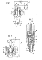
- FIG. 1 shows a simplified representation of the first exemplary embodiment
- FIG. 2 shows a simplified representation of the second exemplary embodiment
- FIG. 3 shows a practical exemplary embodiment of a signal transmitter that can be used in the second exemplary embodiment
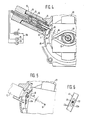
- FIG. 4 shows the third exemplary embodiment with a practical one shown in cross section Embodiment of a signal transmitter that can be used in the first embodiment
- FIG. 5 shows a partial sectional view of the third embodiment with the tool shown for fastening the angle encoder mark
- FIG. 6 shows a partially shown section along the line VI-VI in FIG. 5.
- a drive or camshaft 10 of a fuel injection pump serving as a rotating body and rotating about an axis of rotation D is mounted in an associated housing 11 and is fixedly connected to a part 13 carrying an angle sensor mark 12.
- the part 13 can be a separate component connected to the drive shaft 10 by a conical connection, but it can also be formed by a centrifugal weight carrier of a centrifugal speed governor.
- a signal transmitter 15 with a transmitter housing 16 made of insulating material is inserted in a receiving bore 14 of the housing 11 and connected to a test circuit 18 provided with a battery 17.
- the signal transmitter 15 receives in its transmitter housing 16 a transmitter body 19 which can be displaced radially to the axis of rotation D and which essentially consists of two, one with its own
- M designated center axis insulating layer 21 is electrically separated, but connected by an adhesive body parts 19a and 19b. Both body parts 19a and 19b are connected to the test circuit 18 via electrical connections 22 and 23 and at the same time serve as switching contacts of a first contact switch 24 and a second contact switch 25.
- one body part 19a is provided with a pin-shaped contact part 26, which in the position shown is in contact with a contact tongue 27 of the first contact switch 24.
- This contact switch 24 can, as shown in solid lines, work as a pure touch switch, but it can also, as indicated by a dashed connection .28 to the ground connection of the battery 17, be designed as a limit switch.
- the first contact switch 24 is part of a coarse display circuit 31 provided with a control lamp 29.
- a cross in the lamp 29 indicates that the coarse display circuit 31 is closed by the switch 24 and emits a corresponding warning signal by the switched on control lamp 29.
- the encoder body 19 has been raised against the force of a return spring 32 by the drive shaft 10, which is rotated in the direction of an arrow P, and by the angle encoder mark 12, which is firmly connected to the latter, for actuating the contact switch 24.
- the encoder body 19 is designed as a molded cam 33 on its outer end face facing the angle encoder mark 12.
- the drive shaft 10 or the part 13 provided with the angle encoder 12 continues to rotate in the direction of the arrow in the z. B. indicated in Figure 2, then the angle encoder mark 12 connects the two body parts 19a and 19b now serving as switching contacts of the second contact switch 25, so that a control lamp 35 inserted into a fine display circuit 34 then lights up.
- the two switch contacts 19a and 19b establish a contact bridge with the angular encoder mark 12, thus forming the second contact switch 25 and triggering a rotational position signal which exactly corresponds to the desired or previously set predetermined rotational position Indicates drive shaft 10.
- the second control lamp 35 goes out again and indicates that the angle encoder mark 12 is no longer in the central position.
- the second exemplary embodiment shown in simplified form in FIG. 2, also contains the test circuit 18 provided with the two indicator lights 29 and 35; however, the two display circuits designated 31 'and 34' are operated in a different way.
- the angle encoder mark 12 fastened to the centrifugal weight carrier 13 is connected via a ground connection 41 to the negative pole of the battery 17 and, depending on its respective position, serves as a switching contact or as the ground contact for the two contact switches of the signal transmitter, designated here as 24 'and 25' 15 '.
- the encoder body 19 ' carries on its outer end face 33 facing the angle encoder mark 12 two contact surfaces 19a' and 19b 'which are insulated from one another and from the encoder body 19' and which, depending on the direction of rotation of the part 13, have the respective other switching contact of the first and second contact switches 24 'and 25 ' form.
- Angle encoder mark 12 firstly forms the contact surface 19a 'and forms the first contact switch 24' inserted into the rough display circuit 31 '. If the angle encoder mark 12 reaches the center position shown, then it also establishes a connection to the second contact surface 19b 'and forms together with this the second contact switch 25' inserted in the fine display circuit 34 '. In the center position shown, both indicator lights 29 and 35 light up, which indicates the exact center position.
- the display circuit 34 ' would act as a coarse display circuit and the display circuit 31' as a fine display circuit and the switch 25 'as the first and the switch 24' as the second contact switch.
- the circuit shown in FIG. 2 thus also shows the respective direction of rotation with the indicator lamp which lights up first, with which the angle encoder mark 12 approaches the central position to be measured.
- the practical exemplary embodiment shown in section in FIG. 3 of the signal transmitter 15 ′′ which can be used in FIG. 2 contains in its transmitter housing 16 made of insulating material a transmitter body which, like in the first exemplary embodiment, is produced from two body parts 19a and 19b by means of an interposed insulating layer 21 and therefore also how 1 in Fig. 1.
- the connections to the test circuit 18 are made as in Fig. 2.
- the signal transmitter 15 "contains a sliding contact 41a, which establishes the ground connection from the battery 17 to the angle encoder mark 12 via a metal knurled screw 41b (see Figure 2).
- a fixing pin 42 fastened in the encoder housing 16 serves both to secure the rotational position of the encoder body 19 relative to the housing 16 and to secure the rotational position of the encoder housing 16 compared to the receiving hole not shown here in the associated housing.
- the lines which are led out of the interior of the signal transmitter 15 "and connected to the switch contacts 19a and 19b are designated 31 'and 34' for simplicity, since they are to be regarded as parts of these two display circuits.
- the signal transmitter 15 provided with the test circuit 18 is inserted into the housing 11 of a centrifugal speed controller 45 by the fixing pin 42 in a rotationally secured manner.
- the signal transmitter 15 shown in longitudinal section corresponds in structure and function to the signal transmitter 15 described in FIG. 1 and carries within the transmitter housing 16 the first contact switch 24 fastened to the housing 16 on an insulating material plate 46.
- FIGS 12 ' from a tab of a sheet metal bracket 48 protruding at right angles from the surface of a sheet metal capsule 47 and riveted to a wall part 47a of this sheet metal capsule 47 by means of a blind rivet 49.
- the sheet metal capsule 47 is part of a centrifugal weight assembly 51 of the speed controller 45, which is attached to an injection pump (not shown in more detail), is fastened in a rotationally fixed manner to this assembly 51 and is connected in a rotationally fixed manner therewith to the drive shaft 10 serving as a rotating body. So that the angle encoder mark 12 'on the sheet metal angle 48 in an exact, z. B. the start of conveyance corresponding rotary position can be attached to the sheet metal capsule 47, the latter is provided with an elongated hole 52 which extends in the circumferential direction of the sheet metal capsule 47 and to better secure the position of the blind rivet 49 and thus the sheet metal angle 48 on its side walls 52a with a finely toothed surface is provided (see Figure 6).
- the test circuit 18 also shines here when the encoder body is exactly in the central position 19 standing angle encoder mark 12 'both control lamps 29 and 35 at the same time.
- 12 'to the drive shaft 10 can either adjust the angle encoder mark 12, 12' itself relative to the drive shaft 10 to compensate for the existing angular deviation, as has been described for FIGS. 4 to 6, or the installation position of the housing 16 can be changed in which 2, is inserted into the correspondingly larger receiving bore 14 of the housing 11 via an eccentric receiving bush 55.
- This receiving bush 55 is slotted on one side for receiving the fixing pin 42, and the slot designated 55a also serves to fix the position of the Receiving sleeve 55 in the housing 11, which for this purpose with a projecting Nose 56 is provided.
- the battery 17 serving as the power supply source can. either be formed by the battery supplying the motor with power, or it can also be formed by a special battery which is accommodated together with the signal generator 15, 15 'and the test circuit 18 in a common housing and can be handled in the same way as a test lamp .
- a special battery which is accommodated together with the signal generator 15, 15 'and the test circuit 18 in a common housing and can be handled in the same way as a test lamp .
- light-emitting diodes or other warning and display devices can also be used.
Landscapes
- Physics & Mathematics (AREA)
- General Physics & Mathematics (AREA)
- Engineering & Computer Science (AREA)
- Mechanical Engineering (AREA)
- Transmission And Conversion Of Sensor Element Output (AREA)
- Measurement Of Length, Angles, Or The Like Using Electric Or Magnetic Means (AREA)
- Rotary Switch, Piano Key Switch, And Lever Switch (AREA)
- Length Measuring Devices With Unspecified Measuring Means (AREA)
Priority Applications (1)
| Application Number | Priority Date | Filing Date | Title |
|---|---|---|---|
| AT82102591T ATE16129T1 (de) | 1981-07-09 | 1982-03-27 | Einrichtung zum einstellen und ueberpruefen einer vorbestimmten drehlage eines rotationskoerpers. |
Applications Claiming Priority (3)
| Application Number | Priority Date | Filing Date | Title |
|---|---|---|---|
| DE3127048 | 1981-07-09 | ||
| DE19813127048 DE3127048A1 (de) | 1981-07-09 | 1981-07-09 | "einrichtung zum ermitteln einer vorbestimmten drehlage eines rotationskoerpers, insbesondere der foerderbeginnstellung der antriebswelle einer kraftstoffeinspritzpumpe fuer brennkraftmaschinen" |
| IN536CA1982 IN172352B (fr) | 1981-07-09 | 1982-05-13 |
Publications (3)
| Publication Number | Publication Date |
|---|---|
| EP0069826A2 true EP0069826A2 (fr) | 1983-01-19 |
| EP0069826A3 EP0069826A3 (en) | 1983-03-30 |
| EP0069826B1 EP0069826B1 (fr) | 1985-10-16 |
Family
ID=25794454
Family Applications (1)
| Application Number | Title | Priority Date | Filing Date |
|---|---|---|---|
| EP82102591A Expired EP0069826B1 (fr) | 1981-07-09 | 1982-03-27 | Dispositif d'ajustage et de contrôle d'une position angulaire prédéterminée d'un corps de rotation |
Country Status (5)
| Country | Link |
|---|---|
| US (1) | US4435128A (fr) |
| EP (1) | EP0069826B1 (fr) |
| JP (1) | JPS5818115A (fr) |
| DE (1) | DE3127048A1 (fr) |
| IN (1) | IN172352B (fr) |
Cited By (1)
| Publication number | Priority date | Publication date | Assignee | Title |
|---|---|---|---|---|
| FR2528569A1 (fr) * | 1982-06-09 | 1983-12-16 | Daimler Benz Ag | Dispositif pour le reglage exact de la position relative de deux pieces |
Families Citing this family (7)
| Publication number | Priority date | Publication date | Assignee | Title |
|---|---|---|---|---|
| JPS6067749A (ja) * | 1983-09-21 | 1985-04-18 | Nippon Denso Co Ltd | 燃料噴射ポンプの噴射時期制御装置 |
| GB8420413D0 (en) * | 1984-08-10 | 1984-09-12 | Lucas Ind Plc | Fuel pumping apparatus |
| US4683747A (en) * | 1986-03-14 | 1987-08-04 | Hall James W | Timing device |
| FR2626363B1 (fr) * | 1988-01-27 | 1993-02-19 | Telemecanique Electrique | Dispositif pour detecter au moins une variable relative au deplacement d'un mobile |
| US5317911A (en) * | 1992-03-16 | 1994-06-07 | Yaraschefski Steven M | Fixture for torquing components of an assembly |
| AU714426B2 (en) * | 1996-03-15 | 2000-01-06 | Patrick Joseph Byrne | Rotary mechanism limit sensing |
| US7832990B2 (en) * | 2005-09-21 | 2010-11-16 | Delphi Technologies Holding S.Arl | Measurement device |
Family Cites Families (15)
| Publication number | Priority date | Publication date | Assignee | Title |
|---|---|---|---|---|
| DE874531C (de) | 1951-11-13 | 1953-04-23 | Bosch Gmbh Robert | Vorrichtung zum Pruefen des Foerderbeginns von Einspritzpumpen fuer Brennkraftmaschinen |
| CH315383A (fr) * | 1953-04-01 | 1956-08-15 | Genevoise Instr Physique | Machine-outil |
| US3155182A (en) * | 1962-12-28 | 1964-11-03 | Michael I Rackman | Scale annunciator |
| FR1404069A (fr) * | 1964-07-24 | 1965-06-25 | Trosseille Ets | Perfectionnements aux indicateurs de position d'un organe mobile de machine-outil |
| US3499226A (en) * | 1968-01-22 | 1970-03-10 | Randcar Corp | Machine indicator |
| US3553671A (en) * | 1968-02-20 | 1971-01-05 | Randcar Corp | Indicating means |
| DE2000997A1 (de) | 1970-01-10 | 1971-07-22 | Bosch Gmbh Robert | Kraftstoffeinspritzpumpe fuer Brennkraftmaschinen |
| DE2229372C3 (de) | 1972-06-16 | 1978-11-30 | Daimler-Benz Ag, 7000 Stuttgart | Vorrichtung zum Prüfen einer elektronisch gesteuerten Kraftstoffeinspritzung und/oder einer elektronischen Zündanlage bei Brennkraftmaschinen |
| FR2337819A1 (fr) * | 1976-01-12 | 1977-08-05 | Sigma Diesel | Perfectionnements apportes aux pompes d'injection pour moteurs a combustion interne et procede pour le calage de telles pompes d'injection |
| DE2652950A1 (de) | 1976-11-22 | 1978-05-24 | Bosch Gmbh Robert | Einrichtung zum festhalten einer in einer kraftstoffeinspritzpumpe fuer brennkraftmaschinen angeordneten antriebswelle |
| JPS5382927A (en) | 1976-12-28 | 1978-07-21 | Nissan Motor Co Ltd | Air-fuel ratio controlling apparatus |
| JPS54113724A (en) | 1978-02-24 | 1979-09-05 | Nippon Denso Co Ltd | Cam shaft locking device of fuel injection pump |
| DE2843039A1 (de) | 1978-10-03 | 1980-04-17 | Kloeckner Humboldt Deutz Ag | Verfahren zum einstellen von hilfsaggregaten bei brennkraftmaschinen |
| DE2949100A1 (de) | 1979-12-06 | 1981-06-11 | Robert Bosch Gmbh, 7000 Stuttgart | Einrichtung zum festhalten einer in einer kraftstoffeinspritzpumpe fuer brennkraftmaschinen angeordneten antriebswelle |
| DE2949018A1 (de) * | 1979-12-06 | 1981-06-11 | Robert Bosch Gmbh, 7000 Stuttgart | Verfahren zum winkelgerechten anbau einer kraftstoffeinspritzpumpe an eine brennkraftmaschine |
-
1981
- 1981-07-09 DE DE19813127048 patent/DE3127048A1/de not_active Withdrawn
-
1982
- 1982-03-27 EP EP82102591A patent/EP0069826B1/fr not_active Expired
- 1982-05-13 IN IN536CA1982 patent/IN172352B/en unknown
- 1982-06-11 US US06/387,399 patent/US4435128A/en not_active Expired - Fee Related
- 1982-07-07 JP JP57117071A patent/JPS5818115A/ja active Granted
Cited By (1)
| Publication number | Priority date | Publication date | Assignee | Title |
|---|---|---|---|---|
| FR2528569A1 (fr) * | 1982-06-09 | 1983-12-16 | Daimler Benz Ag | Dispositif pour le reglage exact de la position relative de deux pieces |
Also Published As
| Publication number | Publication date |
|---|---|
| EP0069826B1 (fr) | 1985-10-16 |
| US4435128A (en) | 1984-03-06 |
| JPH0326323B2 (fr) | 1991-04-10 |
| DE3127048A1 (de) | 1983-01-20 |
| IN172352B (fr) | 1993-06-26 |
| EP0069826A3 (en) | 1983-03-30 |
| JPS5818115A (ja) | 1983-02-02 |
Similar Documents
| Publication | Publication Date | Title |
|---|---|---|
| DE10026048C2 (de) | Vorrichtung zur haptischen Signalgebung | |
| DE2616693A1 (de) | Zuendanlage, insbesondere fuer brennkraftmaschinen | |
| DE2443413A1 (de) | Verfahren und einrichtung zur regelung des betriebsverhaltens einer brennkraftmaschine | |
| DE2630776A1 (de) | Verfahren und vorrichtung zur ermittlung und einstellung des zuendwinkels von dieselmotoren | |
| DE4302925C2 (de) | Verfahren und Vorrichtung zur Fehlermeldung bei Fahrzeugen | |
| EP0069826A2 (fr) | Dispositif d'ajustage et de contrôle d'une position angulaire prédéterminée d'un corps de rotation | |
| DE3226849A1 (de) | Vorrichtung zum ueberwachen eines drucksensors | |
| EP0123731A1 (fr) | Dispositif pour transmettre la position d'un élément de commande | |
| DE2949100C2 (fr) | ||
| DE3210889A1 (de) | Schraubvorrichtung | |
| WO1987006303A1 (fr) | Dispositif de detection du debut de l'injection dans un moteur diesel | |
| DE2044383C3 (de) | Elektrische Kontrollschaltang für eine zentrale Warnleuchte von Fahrzeugen | |
| DE3151214A1 (de) | Anordnung zum regeln der motordrehzahl fuer ein fahrzeug | |
| DE2636235A1 (de) | Verfahren und vorrichtung zur erzeugung periodisch wiederkehrender steuersignale, insbesondere zur verstellung des zuendzeitpunktes eines verbrennungsmotors | |
| DE4024339C2 (de) | Beschleunigungsdetektor | |
| DE2236197A1 (de) | Einrichtung zur elektronischen verstellung des zuendzeitpunktes in zuendanlagen von brennkraftmaschinen | |
| DE8120023U1 (de) | "Einrichtung zum Ermitteln einer vorbestimmten Drehlage eines Rotationskörpers, insbesondere der Förderbeginnstellung der Antriebswelle einer Kraftstoffeinspritzpumpe für Brennkraftmaschinen" | |
| DE7717931U1 (de) | Steuereinrichtung fuer einspritzbrennkraftmaschinen | |
| WO2001063211A1 (fr) | Dispositif de mesure pour la determination sans contact d"un angle de rotation | |
| DE1963988C3 (de) | Strömungstaster | |
| DE1918574B2 (de) | Vorrichtung zur optischen anzeige einer vollbremsung bei einem kraftfahrzeug | |
| EP0608229A1 (fr) | Systeme d'allumage pour moteurs a combustion interne. | |
| DE8714461U1 (de) | Scheinwerfer für Fahrzeuge, insbesondere Kraftfahrzeuge | |
| DE2526662A1 (de) | Uebertragungsgestaenge | |
| DE542221C (de) | Geschwindigkeitsueberwachungsvorrichtung fuer Kraftfahrzeuge |
Legal Events
| Date | Code | Title | Description |
|---|---|---|---|
| PUAI | Public reference made under article 153(3) epc to a published international application that has entered the european phase |
Free format text: ORIGINAL CODE: 0009012 |
|
| 17P | Request for examination filed |
Effective date: 19820327 |
|
| AK | Designated contracting states |
Designated state(s): AT DE FR GB IT |
|
| PUAL | Search report despatched |
Free format text: ORIGINAL CODE: 0009013 |
|
| AK | Designated contracting states |
Designated state(s): AT DE FR GB IT |
|
| ITF | It: translation for a ep patent filed | ||
| GRAA | (expected) grant |
Free format text: ORIGINAL CODE: 0009210 |
|
| AK | Designated contracting states |
Designated state(s): AT DE FR GB IT |
|
| REF | Corresponds to: |
Ref document number: 16129 Country of ref document: AT Date of ref document: 19851115 Kind code of ref document: T |
|
| REF | Corresponds to: |
Ref document number: 3266894 Country of ref document: DE Date of ref document: 19851121 |
|
| ET | Fr: translation filed | ||
| PLBE | No opposition filed within time limit |
Free format text: ORIGINAL CODE: 0009261 |
|
| STAA | Information on the status of an ep patent application or granted ep patent |
Free format text: STATUS: NO OPPOSITION FILED WITHIN TIME LIMIT |
|
| 26N | No opposition filed | ||
| PGFP | Annual fee paid to national office [announced via postgrant information from national office to epo] |
Ref country code: AT Payment date: 19870326 Year of fee payment: 6 |
|
| PG25 | Lapsed in a contracting state [announced via postgrant information from national office to epo] |
Ref country code: AT Effective date: 19890327 |
|
| ITTA | It: last paid annual fee | ||
| PGFP | Annual fee paid to national office [announced via postgrant information from national office to epo] |
Ref country code: GB Payment date: 20010313 Year of fee payment: 20 |
|
| PGFP | Annual fee paid to national office [announced via postgrant information from national office to epo] |
Ref country code: FR Payment date: 20010323 Year of fee payment: 20 |
|
| PGFP | Annual fee paid to national office [announced via postgrant information from national office to epo] |
Ref country code: DE Payment date: 20010525 Year of fee payment: 20 |
|
| REG | Reference to a national code |
Ref country code: GB Ref legal event code: IF02 |
|
| PG25 | Lapsed in a contracting state [announced via postgrant information from national office to epo] |
Ref country code: GB Free format text: LAPSE BECAUSE OF EXPIRATION OF PROTECTION Effective date: 20020326 |
|
| REG | Reference to a national code |
Ref country code: GB Ref legal event code: PE20 Effective date: 20020326 |