EP0069844A2 - Mine - Google Patents
Mine Download PDFInfo
- Publication number
- EP0069844A2 EP0069844A2 EP82104286A EP82104286A EP0069844A2 EP 0069844 A2 EP0069844 A2 EP 0069844A2 EP 82104286 A EP82104286 A EP 82104286A EP 82104286 A EP82104286 A EP 82104286A EP 0069844 A2 EP0069844 A2 EP 0069844A2
- Authority
- EP
- European Patent Office
- Prior art keywords
- ring
- round cord
- cap
- groove
- mine
- Prior art date
- Legal status (The legal status is an assumption and is not a legal conclusion. Google has not performed a legal analysis and makes no representation as to the accuracy of the status listed.)
- Granted
Links
Images
Classifications
-
- F—MECHANICAL ENGINEERING; LIGHTING; HEATING; WEAPONS; BLASTING
- F42—AMMUNITION; BLASTING
- F42B—EXPLOSIVE CHARGES, e.g. FOR BLASTING, FIREWORKS, AMMUNITION
- F42B23/00—Land mines ; Land torpedoes
Definitions
- the invention relates to a mine with an explosive and detonator-containing housing and a cap, in which an actuating element for the detonator and a locking element cooperating with it is arranged, which can be pivoted by means of a focus lever from the locked position into a release position for the actuating element, wherein the sharpening lever has a ring arranged concentrically to the cap axis, with its end faces slidably mounted on the cap, acting on the locking member, the bearing gaps of which are sealed by round cord rings inserted into its end faces.
- the focus lever should only be able to be moved from the safe position to the focus position with a certain torque. This limit should be such that the sharpening lever does not have to apply excessive torque to the person who is armed to arm the mine.
- the torque must therefore be on the one hand a certain size, but on the other hand also within a certain tolerance range. These sizes must not change even after long storage.
- Both the bearing and the seal must also be such that the function and the necessary actuation torque are not impaired or only slightly changed at extreme temperature differences between approx. -30 ° C and + 50 ° C.
- the seal must ensure tightness against dust and water, possibly also sea water, which in turn requires a certain compression of the seal. However, this pressing must not be too great, since otherwise the torque to be applied to the sharpness lever will be too great.
- the invention has for its object to improve the previously used cord rings in the sense of the aforementioned requirements.
- each round cord ring has a circumferential circumferential notch and is inserted so that the notch is open to the side.
- the notch is preferably designed as a V-groove which, according to a further feature of the invention, is arranged such that the center axis of the round cord ring lies within the groove.
- the round cord ring which as before is made of a comparatively hard rubber, e.g. B. Perbunan, receives an additional elastic resilience through the notch. In this way, the compression can first be increased and thus the tightness in the area of the bearing of the ring can be improved. Practical tests have shown that absolutely dust and waterproof storage has indeed been achieved with the simplest construction. Furthermore, the pressing can be adjusted without difficulty in such a way that the desired actuation torque for the sharpness lever can be maintained, even in the case of extremely low temperatures, without the tightness suffering as a result.
- a comparatively hard rubber e.g. B. Perbunan
- the V-groove starts from the outer apex line of the round cord ring, so it opens to the outside. This not only facilitates the production of the round cord ring, but also has the further advantage that when it occurs a pressure wave, which penetrates into the bearing gap from outside, the O-ring is additionally pressed against the sealing surfaces by widening the V-groove, so the tightness is increased.
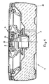
- the mine designated as a whole by 1, has a housing 2 which includes the explosive and a detonator 3. At its center, the housing 2 is closed on the upper side by a cap 4, in which an actuator 5 for the igniter 3 is arranged.
- the actuator 5 interacts with a partially spherical head 6 of the igniter 3.
- the detailed structure of the mine is irrelevant in the present context and is otherwise known.
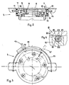
- the cap 4 can be seen in more detail in FIGS. 2 and 3. It consists essentially of a cyl Indian housing ring 7 and a Deckpl atte 8. Inside the housing ring 7, the actuator 5 is seated under the action of a Spring 9 stands. Locking elements in the form of bolts 10 hold the actuating element in the upper position, the securing, shown in the left part of FIG. 2. The bolts 10, in turn, are fixed in the locked position by a ring 11 acting on the outside thereof, which has a plurality of axially parallel recesses 12, into which the bolts 10 can retract under the action of the spring 9, so that the actuator 5 can be seen in the one shown in FIG. 2 on the right Position that can be brought into focus from which the detonator is actuated when pressure is applied from above.
- the one-piece sharpness lever 13 engages approximately radially, which can be pivoted from the position shown in solid line in FIG in the right half in FIG. 2.
- the sharpness lever 13 runs on a de cap on a part of its circumference surrounding resilient support bracket 14 which has a stop ring 15 between the two positions of the sharpness lever 13.
- the focus lever can only be moved in the direction of the focus if the support bracket is previously pressed down by pressure on the plate 17.
- the ring 11 is mounted between a collar 17 on the housing ring 7 of the cap 4 and the underside of the cover plate 8 with its end faces.
- the storage is shown in more detail in Figure 4.
- the ring 11 has on its two end faces an annular groove 18 into which a round cord ring 19 is inserted, which seals the bearing gap 20 between the cover plate 8 and ring 11 or between the latter and the collar 17.
- the pressing takes place in such a way that the cover plate 8 is screwed onto the housing ring 7.
- the round cord ring 19, as can be seen in FIG. 4, is provided with a notch 21 in the form of a V-groove, which is provided on the outer periphery of the round cord ring 19.
- the groove is inserted so deeply into the round cord ring 19 that its base 22 is located beyond the central axis 23 of the round cord ring 19.
Landscapes
- Engineering & Computer Science (AREA)
- General Engineering & Computer Science (AREA)
- Air Bags (AREA)
- Transition And Organic Metals Composition Catalysts For Addition Polymerization (AREA)
- Portable Nailing Machines And Staplers (AREA)
Priority Applications (1)
| Application Number | Priority Date | Filing Date | Title |
|---|---|---|---|
| AT82104286T ATE10788T1 (de) | 1981-05-30 | 1982-05-15 | Mine. |
Applications Claiming Priority (2)
| Application Number | Priority Date | Filing Date | Title |
|---|---|---|---|
| DE19813121627 DE3121627A1 (de) | 1981-05-30 | 1981-05-30 | Mine |
| DE3121627 | 1981-05-30 |
Publications (3)
| Publication Number | Publication Date |
|---|---|
| EP0069844A2 true EP0069844A2 (fr) | 1983-01-19 |
| EP0069844A3 EP0069844A3 (en) | 1983-03-16 |
| EP0069844B1 EP0069844B1 (fr) | 1984-12-12 |
Family
ID=6133615
Family Applications (1)
| Application Number | Title | Priority Date | Filing Date |
|---|---|---|---|
| EP82104286A Expired EP0069844B1 (fr) | 1981-05-30 | 1982-05-15 | Mine |
Country Status (3)
| Country | Link |
|---|---|
| EP (1) | EP0069844B1 (fr) |
| AT (1) | ATE10788T1 (fr) |
| DE (2) | DE3121627A1 (fr) |
Cited By (2)
| Publication number | Priority date | Publication date | Assignee | Title |
|---|---|---|---|---|
| EP0119383A1 (fr) * | 1983-01-12 | 1984-09-26 | NICO-PYROTECHNIK Hanns-Jürgen Diederichs GmbH & Co. KG | Dispositif d'allumage |
| AU648307B2 (en) * | 1991-05-01 | 1994-04-21 | Mark Robert Trist | Cartridge mine |
Family Cites Families (2)
| Publication number | Priority date | Publication date | Assignee | Title |
|---|---|---|---|---|
| BE616140A (fr) * | 1961-04-27 | |||
| FR1405803A (fr) * | 1961-04-27 | 1965-07-16 | Karlsruhe Augsburg Iweka | Mine de campagne |
-
1981
- 1981-05-30 DE DE19813121627 patent/DE3121627A1/de not_active Withdrawn
-
1982
- 1982-05-15 AT AT82104286T patent/ATE10788T1/de not_active IP Right Cessation
- 1982-05-15 EP EP82104286A patent/EP0069844B1/fr not_active Expired
- 1982-05-15 DE DE8282104286T patent/DE3261527D1/de not_active Expired
Cited By (2)
| Publication number | Priority date | Publication date | Assignee | Title |
|---|---|---|---|---|
| EP0119383A1 (fr) * | 1983-01-12 | 1984-09-26 | NICO-PYROTECHNIK Hanns-Jürgen Diederichs GmbH & Co. KG | Dispositif d'allumage |
| AU648307B2 (en) * | 1991-05-01 | 1994-04-21 | Mark Robert Trist | Cartridge mine |
Also Published As
| Publication number | Publication date |
|---|---|
| DE3121627A1 (de) | 1982-12-23 |
| EP0069844A3 (en) | 1983-03-16 |
| ATE10788T1 (de) | 1984-12-15 |
| EP0069844B1 (fr) | 1984-12-12 |
| DE3261527D1 (en) | 1985-01-24 |
Similar Documents
| Publication | Publication Date | Title |
|---|---|---|
| DE69118804T3 (de) | Gefederte Packungsstopfbuchse | |
| DE1909257A1 (de) | Ventil | |
| DE1600811B2 (de) | Zu- und abflusseitige dichtringanordnung fuer einen kugelhahn | |
| DE2020847B2 (de) | Federnder sicherungsring fuer radiale montage | |
| EP0604608B1 (fr) | Robinet d'arret | |
| DE3246622C2 (de) | Molchbare Absperrarmatur | |
| EP1498635B1 (fr) | Elément de réglage comportant un cylindre | |
| DE2255447A1 (de) | Sicherungselement | |
| DE3511554A1 (de) | Gasfeder | |
| EP0541894B1 (fr) | Dispositif d'étanchéité | |
| DE2445377B2 (de) | Vorrichtung zum schrittweisen Einstellen der Dämpfkraft eines Stoßdämpfe | |
| EP0424360A2 (fr) | Dispositif d'obturation | |
| DE29711184U1 (de) | Hydro-Spannelement | |
| EP0069844B1 (fr) | Mine | |
| DE3436579A1 (de) | Vorrichtung zum verbinden zweier rohrenden | |
| DE19542513C2 (de) | Hohle Kolbenstange für ein Kolben-Zylinderaggregat | |
| DE2830891A1 (de) | Sicherheitsventil | |
| DE2729928B2 (fr) | ||
| EP0021110B1 (fr) | Robinet à boisseau sphérique | |
| DE3712819C2 (fr) | ||
| EP0364407A2 (fr) | Dispositif d'étanchéité pour soupapes ou brides, notamment pour système de vide | |
| DE2618115C3 (de) | Absperrhahn | |
| DE3719155A1 (de) | In einem gehaeuse untergebrachte sicherheitsklemmvorrichtung zum verklemmen der kolbenstange eines hubzylinders | |
| DE3532988C2 (de) | Elektrohydraulische Schaltvorrichtung | |
| DE4317483A1 (de) | Kolben, insbesondere für den Servozylinder einer Hilfskraftlenkanlage |
Legal Events
| Date | Code | Title | Description |
|---|---|---|---|
| PUAI | Public reference made under article 153(3) epc to a published international application that has entered the european phase |
Free format text: ORIGINAL CODE: 0009012 |
|
| PUAL | Search report despatched |
Free format text: ORIGINAL CODE: 0009013 |
|
| AK | Designated contracting states |
Designated state(s): AT BE CH DE FR GB IT LI LU NL SE |
|
| AK | Designated contracting states |
Designated state(s): AT BE CH DE FR GB IT LI LU NL SE |
|
| 17P | Request for examination filed |
Effective date: 19830126 |
|
| RAP1 | Party data changed (applicant data changed or rights of an application transferred) |
Owner name: INDUSTRIE-WERKE KARLSRUHE AUGSBURG AKTIENGESELLSCH |
|
| GRAA | (expected) grant |
Free format text: ORIGINAL CODE: 0009210 |
|
| AK | Designated contracting states |
Designated state(s): AT BE CH DE FR GB IT LI LU NL SE |
|
| PG25 | Lapsed in a contracting state [announced via postgrant information from national office to epo] |
Ref country code: SE Effective date: 19841212 Ref country code: NL Effective date: 19841212 Ref country code: IT Free format text: LAPSE BECAUSE OF FAILURE TO SUBMIT A TRANSLATION OF THE DESCRIPTION OR TO PAY THE FEE WITHIN THE PRESCRIBED TIME-LIMIT;WARNING: LAPSES OF ITALIAN PATENTS WITH EFFECTIVE DATE BEFORE 2007 MAY HAVE OCCURRED AT ANY TIME BEFORE 2007. THE CORRECT EFFECTIVE DATE MAY BE DIFFERENT FROM THE ONE RECORDED. Effective date: 19841212 Ref country code: FR Free format text: THE PATENT HAS BEEN ANNULLED BY A DECISION OF A NATIONAL AUTHORITY Effective date: 19841212 Ref country code: BE Effective date: 19841212 |
|
| REF | Corresponds to: |
Ref document number: 10788 Country of ref document: AT Date of ref document: 19841215 Kind code of ref document: T |
|
| REF | Corresponds to: |
Ref document number: 3261527 Country of ref document: DE Date of ref document: 19850124 |
|
| PG25 | Lapsed in a contracting state [announced via postgrant information from national office to epo] |
Ref country code: AT Effective date: 19850515 |
|
| NLV1 | Nl: lapsed or annulled due to failure to fulfill the requirements of art. 29p and 29m of the patents act | ||
| PG25 | Lapsed in a contracting state [announced via postgrant information from national office to epo] |
Ref country code: LU Free format text: LAPSE BECAUSE OF NON-PAYMENT OF DUE FEES Effective date: 19850531 Ref country code: LI Effective date: 19850531 Ref country code: CH Effective date: 19850531 |
|
| EN | Fr: translation not filed | ||
| PLBE | No opposition filed within time limit |
Free format text: ORIGINAL CODE: 0009261 |
|
| STAA | Information on the status of an ep patent application or granted ep patent |
Free format text: STATUS: NO OPPOSITION FILED WITHIN TIME LIMIT |
|
| 26N | No opposition filed | ||
| REG | Reference to a national code |
Ref country code: CH Ref legal event code: PL |
|
| GBPC | Gb: european patent ceased through non-payment of renewal fee | ||
| PG25 | Lapsed in a contracting state [announced via postgrant information from national office to epo] |
Ref country code: GB Effective date: 19881121 |
|
| PGFP | Annual fee paid to national office [announced via postgrant information from national office to epo] |
Ref country code: DE Payment date: 19900720 Year of fee payment: 9 |
|
| PG25 | Lapsed in a contracting state [announced via postgrant information from national office to epo] |
Ref country code: DE Effective date: 19920303 |