EP0069915A1 - Mécanisme de déverrouillage de secours pour portes de véhicule - Google Patents
Mécanisme de déverrouillage de secours pour portes de véhicule Download PDFInfo
- Publication number
- EP0069915A1 EP0069915A1 EP82105787A EP82105787A EP0069915A1 EP 0069915 A1 EP0069915 A1 EP 0069915A1 EP 82105787 A EP82105787 A EP 82105787A EP 82105787 A EP82105787 A EP 82105787A EP 0069915 A1 EP0069915 A1 EP 0069915A1
- Authority
- EP
- European Patent Office
- Prior art keywords
- inertia
- lever
- actuating
- lock
- arm
- Prior art date
- Legal status (The legal status is an assumption and is not a legal conclusion. Google has not performed a legal analysis and makes no representation as to the accuracy of the status listed.)
- Granted
Links
- 230000001133 acceleration Effects 0.000 claims abstract description 12
- 230000033001 locomotion Effects 0.000 claims abstract description 10
- 230000005540 biological transmission Effects 0.000 description 6
- 230000000694 effects Effects 0.000 description 2
- 230000003111 delayed effect Effects 0.000 description 1
Images


Classifications
-
- E—FIXED CONSTRUCTIONS
- E05—LOCKS; KEYS; WINDOW OR DOOR FITTINGS; SAFES
- E05B—LOCKS; ACCESSORIES THEREFOR; HANDCUFFS
- E05B77/00—Vehicle locks characterised by special functions or purposes
- E05B77/02—Vehicle locks characterised by special functions or purposes for accident situations
- E05B77/12—Automatic locking or unlocking at the moment of collision
-
- Y—GENERAL TAGGING OF NEW TECHNOLOGICAL DEVELOPMENTS; GENERAL TAGGING OF CROSS-SECTIONAL TECHNOLOGIES SPANNING OVER SEVERAL SECTIONS OF THE IPC; TECHNICAL SUBJECTS COVERED BY FORMER USPC CROSS-REFERENCE ART COLLECTIONS [XRACs] AND DIGESTS
- Y10—TECHNICAL SUBJECTS COVERED BY FORMER USPC
- Y10S—TECHNICAL SUBJECTS COVERED BY FORMER USPC CROSS-REFERENCE ART COLLECTIONS [XRACs] AND DIGESTS
- Y10S292/00—Closure fasteners
- Y10S292/22—Inertia operated
-
- Y—GENERAL TAGGING OF NEW TECHNOLOGICAL DEVELOPMENTS; GENERAL TAGGING OF CROSS-SECTIONAL TECHNOLOGIES SPANNING OVER SEVERAL SECTIONS OF THE IPC; TECHNICAL SUBJECTS COVERED BY FORMER USPC CROSS-REFERENCE ART COLLECTIONS [XRACs] AND DIGESTS
- Y10—TECHNICAL SUBJECTS COVERED BY FORMER USPC
- Y10T—TECHNICAL SUBJECTS COVERED BY FORMER US CLASSIFICATION
- Y10T292/00—Closure fasteners
- Y10T292/08—Bolts
- Y10T292/1043—Swinging
- Y10T292/1075—Operating means
- Y10T292/1082—Motor
Definitions
- the present invention relates to a locking system for a door of an automobile, and more specifically to a locking system having an emergency unlocking mechanism.
- Doors of an automobile are locked and unlocked by manipulating a door lock cylinder from the outside or a door lock knob from the inside. If an automobile comes into collision with its doors locked and the driver and passengers become unable to move within the automobile, the rescue of them is delayed because the doors can not be easily opened from the outside.
- an automatic door locking system having a so-called G sensor for detecting acceleration of a vehicle has been proposed.
- this system is arranged to automatically unlock the door in response to the output signal of the G sensor by using an electromechanical system, and therefore, requires many costly electrical devices.
- the reliability of such a system is not sufficient because it is subject to electric contact failure.
- a locking system comprises a lock unit for locking and unlocking the door, linkage means connected with the lock unit for transmitting movement caused by manipulation to the lock unit, and inertia actuating means which can move by reason of its inertia when a deceleration of a rate higher than a predetermined level takes place, and causes the linkage means to move in such a direction as to move the lock unit into its unlocking position.
- the lock unit has a locking position in which the door is locked and an unlocking position in which the door is not locked
- the linkage means has a lock directing position in which the linkage means puts the lock unit in its locking position and an unlock directing position in which the linkage means puts the lock unit in its unlocking position.
- the inertia actuating means is normally held in a normal position but is movable to a first actuating position.
- the inertia actuating means moves from its normal position to its first actuating position by reason of its inertia.
- the inertia actuating means causes the linkage means to move from its lock directing position to its unlock directing position thereby to cause the lock unit to move from its locking position to its unlocking position.
- the inertia-actuating means comprises an inertia lever which has a weight pendulum and can swing in a vertical plane on a flucrum from its normal position to its first actuating position, and holding means for normally holding the inertia lever in its normal position and allowing the inertia lever to swing to its first actuating position when a deceleration of a rate higher than the predetermined level takes place.
- a door lock unit 1 is fastened to the rear end of a door (not shown), and an outside handle 3 and an inside handle 4 are fixed, respectively, to an outer panel and an inner panel of of the door.
- the outside handle 3 and the inside handle 4 are connected with a release lever 8 of the door lock unit 1 by rods 6 and 7, respectively.
- the release lever 8 actuates a locking plate (not shown) to release a latch 10 from the engagement with a'door striker (not shown) fixed to a vehicle body.
- a lock linkage 11 which comprises, in this embodiment, a door lock knob rod 13 connected to a door lock knob 12, a bell crank 14, an intermediate rod 15, and a lock lever 16.
- the lower end of the door lock knob rod 13 is connected with a first arm of the bell crank 14 by a joint pin.17 forming a pin joint.
- the bell crank 14 is pivotally mounted, with the interposition of a base plate or directly, on the inner panel 18 of the door by a fulcrum pin 19.
- a second arm of the bell crank 14 is connected with one end of the intermediate rod 15 by a joint pin 20 forming a pin joint.
- the lock lever 16 is pivotally mounted on the door lock unit 1 by a pin 21 and connected with the intermediate rod 15.
- the lock linkage 1,1 transmits this motion through the bell crank 14, and the intermediate rod 15, to the lock lever 16 and, brings the lock lever 16 to its locking position.
- the release lever 8 is made unable to perform its function, and therefore, the door can not be opened by the outside handle 3 and the inside handle 4.
- the lock lever 16 can be also actuated by a lock cylinder fixed to the outer panel of the door. The lock lever 16 can be returned to its unlocking position by pulling the lock knob 12. When the lock lever 16 is in its unlocking position, the door can be opened freely by the outside handle 3 or the inside handle 4.
- an inertia actuator 30 which detects a predetermined deceleration with the aid of inertia and forces the lock linkage 11 to move toward the unlocking direction.
- the inertia actuator 30 is mounted in relation with the bell crank 14.
- the inertia actuator 30 mainly comprises an inertia lever 31 having, in its lower end, a weight portion 32, and holding means such as a setting spring 33 for normally holding the weight portion 32 in its inoperative state.
- the inertia lever 31 is pivotally supported on the fulcrum pin 19 on which the bell crank 14 is also pivoted in common.
- the inertia lever 31 has, in one side, an actuating portion 34 which is in contact with or close to the underside of the knob rod side first arm of the bell crank 14 when the bell crank 14 is in its locking position with the knob rod being pushed down.
- the inertia lever has, in the other side, a stop portion 35 which is loosely received in a slide slit 23 formed in the base plate (not shown) or the inner panel 18 of the door.
- the spring 33 is mounted on the fulcrum pin 19. One end of the spring 33 is fixed to the base plate or the inner panel 18 of the door, and the other end thereof is fixed to the inertia lever 31.
- the spring 33 holds the inertia lever 31 in the position in which the stop portion 35 of the inertia lever 31 abuts against the right end, in Fig. 2A, of the slide slit 23.
- the holding means of the spring 33 restricts the inertial movement of the inertia lever 31.
- the spring 33 holds the inertia lever 33 stationary irrespective of deceleration during- abrupt braking or during the vehicle is bouncing along a rugged road.
- the spring 33 allows the inertia lever 31 to move under the influence of inertia only when the inertia lever undergoes more steep deceleration or acceleration as in the case of collision causing heavy damage of the vehicle.
- the spring constant of the spring 33 is appropriately adjusted.
- the inertia lever 31 swings toward the clockwise direction in Fig. 2B by reason of its inertia. By this swing movement, the inertia lever 31 pushes up the lock knob side arm of the bell crank 14, as shown in Fig. 2B, and turns the lock lever 16 through the intermediate rod 15 to unlock the lock unit 1.
- the door can be opened from the outside of the vehicle by manipulating the outside handle. The door can be also opened by the inside handle, of course.
- the inertia lever 31 returns to its original normal position, as shown in Fig. 3C, by force of the spring 33.
- the inertia actuator can be activated by a rear end collision as well.
- An inertia lever 31 of this embodiment is pivotally mounted on the inner panel 18 of the door, for example, by means of a pin 36 at a position between the fulcrum of the bell crank 14, that is, the position.of the pin 19, and the joint point of the knob rod 13, that is, the position of the pin 17.
- the inertia lever 31 is formed, at its intermediate portion, with an actuating portion 37 which lies adjacent, touching or not touching, to the underside of the knob rod side arm of the bell crank 14.
- a spring 33 is mounted between the underside of a weight portion 32 and the inner panel 18 of the door.
- a predetermined deceleration causes the-inertia lever 31 to swing toward the clockwise direction in Fig. 3 by reason of inertia, and this pushes up the knob rod side arm of the bell crank 14 thus to effect automatic unlocking of the lock unit 1.
- a predetermined acceleration causes the inertia lever 31 to swing toward the counterclockwise direction in Fig. 3 and to push up the knob rod side arm of the bell crank 14. Therefore, the lock unit 1 is automatically and reliably unlocked in the case of acceleration, too.
- an inertia actuator 30 is activated by deceleration and acceleration in a symmetrical manner.
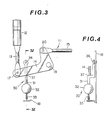
- an inertia lever 31 is pivotally mounted on the side of the door, that is, the inner panel ⁇ f ⁇ the door, for example, by means of a pin 36 at a position under the joint of the knob rod 13, that is, the position of the pin 17.
- a spring 33 is disposed between the underside of a weight portion 32 of the inertia lever 31 and the inner panel 18 of the door in the same manner as the embodiment of Figs. 3 and 4.
- a transmission or actuating lever 38 is connected with the pin 17, and the lower end of the transmission lever 38 is connected with the weight portion 32 of the inertia lever 31 by a joint pin 39 forming a pin joint at a position on the center line of the inertia lever 31.
- the transmission lever 38 is formed with a longitudinally extending slit 40 in which the pin 17 is received,-so that the transmission lever 38 is not moved by the up and down movements of the knob rod 13 in normal use.
- the connecting point of the knob rod, the fulcrum of the inertia lever, the connecting points of the transmission lever and the connecting points of the spring are.all placed on a straight line as mentioned above. Accordingly, in both the case of deceleration in which the inertia lever 31 swings toward the clockwise direction as shown in Fig. 5B and the case of acceleration in which the.inertia lever 31 swings toward the counterclockwise direction as shown in Fig. 5C, deceleration and acceleration of the same rate cause the inertia lever 31 to swing to the same degree. Besides, inertial motion is transmitted through the transmission lever 38 to the bell crank 14 at the same point, that is, the connecting point of the knob rod 13 or the point of the pin 17. Thus, the operations caused by inertia are the same both in the cases of deceleration and acceleration, so that the reliability is improved.
- the inertia actuator 30 is related with the bell crank 14. If, however, the lock linkage 11 does not include a bell crank and the knob rod 13 connected with the lock knob 12 is directly connected with the lock lever 16, it is possible to relate the inertia actuator 30 with the knob rod 13, as shown in Fig. 6. In this case, the knob rod 13 is formed with an arm portion 41 at the intermediate portion.
- An inertia lever 31 of this embodiment is pivotally mounted on the side of the door, that is, the inner panel 18 of the door, for example, by means of a pin 36.
- An actuating portion 34 is formed in the inertia lever 31 at such a position that the actuating portion 34 lies near or in contact with the underside of the arm portion 41 of the knob rod 13 when the knob rod 13 is in its locking position.
- a setting spring 33 is disposed between a weight portion 32 of the inertia lever 31 and the inner panel 18. Thus, the setting spring 33 holds the inertia lever 31 in its stationary normal position in which a stopper portion 35 formed in the other side of the inertia lever 31 abuts on a stopper portion 24 formed in the inner panel 18 of the door.
- the inertia lever 31 of this embodiment moves toward the clockwise direction in Fig. 6 by means of inertia and directly pushes up the knob rod 13 through its arm portion 41 thereby to automatically unlock the -lock unit 1.
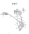
- the present invention is applied to the arrangement in which the lower end of a knob rod is directly connected with a lock lever 16.
- the lock lever 16 is engaged with an arm portion 25a of an key lever 25 which is connected with a door lock cylinder 43 shown in Fig. 7 through a key rod 44.
- the knob rod 13 is pushed down, the lock lever 16 pushes up the arm portion 25a of the key lever 25 into its locking position, and when the knob rod 13 is pulled up, it pushes down the key portion 25a into its unlocking _position.
- a setting spring 33 is extended between a portion of the inertia lever 31 adjace to a weight portion 32 and the lower end of a casing 1a of the door lock unit 1.
- the setting spring 33 holds the inertia lever 31 stationary in such a position that a stopper portion 35 formed in one side of the inertia lever 31 abuts on a stopper portion 1b formed in the underside of the casing 1a.
- the lock lever 16 is formed, in the lower portion, with an arm portion 42 which projects toward the stopper portion 1b. The arm portion 42 lies close to or in contact with the stopper portion 35 of the inertia lever 31 when the lock lever 16 is in its locking position with the knob rod being pushed down.
- the inertia lever 31 of this embodiment swings toward the clockwise direction in Fig. 8 by means of inertia and directly turns the lock lever 16 toward the unlocking direction to effect automatic unlocking.
Landscapes
- Lock And Its Accessories (AREA)
Applications Claiming Priority (2)
| Application Number | Priority Date | Filing Date | Title |
|---|---|---|---|
| JP107434/81 | 1981-07-08 | ||
| JP56107434A JPS5811275A (ja) | 1981-07-08 | 1981-07-08 | 自動車の緊急ドアロツク解錠装置 |
Publications (2)
| Publication Number | Publication Date |
|---|---|
| EP0069915A1 true EP0069915A1 (fr) | 1983-01-19 |
| EP0069915B1 EP0069915B1 (fr) | 1985-11-21 |
Family
ID=14459038
Family Applications (1)
| Application Number | Title | Priority Date | Filing Date |
|---|---|---|---|
| EP82105787A Expired EP0069915B1 (fr) | 1981-07-08 | 1982-06-29 | Mécanisme de déverrouillage de secours pour portes de véhicule |
Country Status (4)
| Country | Link |
|---|---|
| US (1) | US4536021A (fr) |
| EP (1) | EP0069915B1 (fr) |
| JP (1) | JPS5811275A (fr) |
| DE (1) | DE3267567D1 (fr) |
Cited By (6)
| Publication number | Priority date | Publication date | Assignee | Title |
|---|---|---|---|---|
| DE4017047A1 (de) * | 1990-05-26 | 1991-11-28 | Opel Adam Ag | Tuerverriegelung fuer kraftfahrzeuge |
| FR2761725A1 (fr) * | 1997-04-03 | 1998-10-09 | Peugeot | Mecanisme de condamnation/decondamnation de porte de vehicule |
| DE19809449A1 (de) * | 1998-03-05 | 1999-09-09 | Volkswagen Ag | Betätigungsvorrichtung für ein Kraftfahrzeug-Türschloß |
| EP0902143A3 (fr) * | 1997-09-10 | 2000-12-27 | Fuji Jukogyo Kabushiki Kaisha | Mécanisme de verrouillage d'une serrure de porte pour un véhicule à moteur |
| DE19635741C2 (de) * | 1995-09-04 | 2003-01-02 | Aisin Seiki | Entriegelungsvorrichtung für ein Türschloß eines Fahrzeugs |
| DE102007052713A1 (de) * | 2007-11-06 | 2009-05-07 | GM Global Technology Operations, Inc., Detroit | Kraftfahrzeugtür |
Families Citing this family (47)
| Publication number | Priority date | Publication date | Assignee | Title |
|---|---|---|---|---|
| JPS59152069U (ja) * | 1983-03-30 | 1984-10-12 | 株式会社大井製作所 | 自動車用ドアロツク装置の施解錠機構 |
| US4643710A (en) * | 1984-10-29 | 1987-02-17 | Mcneilab, Inc. | Valve apparatus for photoactivation patient treatment system |
| US4879061A (en) * | 1986-09-29 | 1989-11-07 | Crystaloid Electronics Co. | Liquid crystalline materials and method of making same |
| JPH0761782B2 (ja) * | 1986-12-04 | 1995-07-05 | アイシン精機株式会社 | 車上シ−トの姿勢制御装置 |
| JPS63151776A (ja) * | 1986-12-12 | 1988-06-24 | アイシン精機株式会社 | 車上施錠機構の緊急解錠装置 |
| JPS63219414A (ja) * | 1987-03-05 | 1988-09-13 | Aisin Seiki Co Ltd | 車内エア吐出装置 |
| JPH082351Y2 (ja) * | 1987-12-02 | 1996-01-24 | 富士重工業株式会社 | 自動車用リッドの自動ロック装置 |
| US5152562A (en) * | 1991-11-05 | 1992-10-06 | Stevenson John M | Shock-actuated lock with resettable ball |
| US5308130A (en) * | 1992-12-18 | 1994-05-03 | General Motors Corporation | Vehicle door latch |
| DE19548562B4 (de) * | 1995-12-23 | 2004-12-16 | Siemens Ag | Einrichtung zur Entriegelung von Türen eines Kraftfahrzeugs |
| DE19610200A1 (de) * | 1996-03-15 | 1997-09-18 | Valeo Deutschland Gmbh & Co | Türaußengriff |
| US7424814B2 (en) * | 1997-02-10 | 2008-09-16 | Lockmasters, Inc. | Dead bolt lock system having multiple security features |
| GB2331119A (en) * | 1997-08-06 | 1999-05-12 | Rockwell Lvs | Vehicle door mechanism with associated rechargeable electric energy storage |
| WO2001066890A2 (fr) * | 2000-03-07 | 2001-09-13 | Southco, Inc. | Verrou sensible a la gravite |
| US6565134B1 (en) * | 2000-04-21 | 2003-05-20 | Adac Plastics, Inc. | Handle with side impact counterweight having installation position |
| US6575508B2 (en) * | 2000-04-21 | 2003-06-10 | Adac Plastics, Inc. | Handle with unidirectional counterweight |
| US6464270B1 (en) * | 2001-05-23 | 2002-10-15 | General Motors Corporation | Exterior handle assembly for motor vehicle door |
| US8056944B2 (en) * | 2002-06-13 | 2011-11-15 | Ford Global Technologies | Latch assembly for a vehicle door |
| GB0214817D0 (en) * | 2002-06-27 | 2002-08-07 | Arvinmeritor Light Vehicle Sys | Door latch mechanism |
| EP1457625A3 (fr) * | 2003-03-08 | 2008-08-27 | Brose Schliesssysteme GmbH & Co. KG | Serrure pour véhicule à ouverture assistée électriquement |
| DE10342578B3 (de) * | 2003-09-15 | 2005-09-15 | Faurecia Innenraum Systeme Gmbh | Gehäuse- und Verschlusselement mit Überschlagsicherung |
| US7070216B2 (en) * | 2004-09-09 | 2006-07-04 | Siegel-Robert, Inc. | Vehicle door handle assembly |
| JP2007303181A (ja) * | 2006-05-12 | 2007-11-22 | Aisin Seiki Co Ltd | ドアロック装置 |
| US8069616B2 (en) * | 2007-09-07 | 2011-12-06 | Brose Schliesssysteme Gmbh & Co. Kg | Method for mounting a motor vehicle door lock |
| EP2195500B1 (fr) * | 2007-10-10 | 2017-05-03 | Magna Closures Inc. | Loquet de porte avec déverrouillage rapide |
| KR100957103B1 (ko) * | 2008-06-30 | 2010-05-13 | 현대자동차주식회사 | 차량용 도어래치장치 |
| US20100088855A1 (en) * | 2008-10-14 | 2010-04-15 | Magna Mirrors Of America, Inc. | Vehicle door handle assembly |
| JP5285524B2 (ja) * | 2009-07-22 | 2013-09-11 | 株式会社アンセイ | 車両用ドアロック装置 |
| US8322077B2 (en) * | 2009-11-23 | 2012-12-04 | Ford Global Technologies, Llc | Vehicle door handle with inertia lock mechanism |
| US8959838B1 (en) * | 2009-12-18 | 2015-02-24 | Vittorio Marinelli | Cargo vehicle security system and method of use |
| US8366159B2 (en) * | 2010-01-06 | 2013-02-05 | Ford Global Technologies, Llc | Multi-lever bi-directional inertia catch mechanism |
| US8485570B2 (en) * | 2010-03-29 | 2013-07-16 | GM Global Technology Operations LLC | Door lock assembly with inertia lock |
| US8342581B2 (en) * | 2010-06-14 | 2013-01-01 | Inteva Products, Llc | Vehicle latch with pendulum stop on release lever |
| US8414038B2 (en) * | 2010-08-12 | 2013-04-09 | Nissan North America, Inc. | Vehicle door latch structure |
| JP5725154B2 (ja) | 2011-03-16 | 2015-05-27 | 株式会社アンセイ | 車両用ドアロック装置 |
| WO2013046317A1 (fr) | 2011-09-27 | 2013-04-04 | 株式会社アンセイ | Dispositif de verrouillage de porte pour véhicule |
| KR101806564B1 (ko) * | 2011-12-12 | 2017-12-08 | 현대자동차주식회사 | 차량의 도어래치장치 |
| CN102642469B (zh) * | 2012-05-17 | 2015-09-02 | 苏州奥杰汽车工业有限公司 | 车辆安全门警示装置 |
| US9085918B2 (en) | 2013-04-09 | 2015-07-21 | GM Global Technology Operations LLC | Status indicator system for a vehicle door lock |
| KR101428410B1 (ko) * | 2013-08-14 | 2014-09-23 | 현대자동차주식회사 | 트럭의 도어 록킹장치 |
| DE102013220382A1 (de) * | 2013-10-09 | 2015-04-09 | Kiekert Ag | Kraftfahrzeugtürverschluss |
| DE102014004550A1 (de) * | 2014-03-31 | 2015-10-01 | Kiekert Aktiengesellschaft | Betätigungseinrichtung für ein Kraftfahrzeugschloss |
| US9995060B2 (en) | 2014-04-14 | 2018-06-12 | Lockmasters Technologies Inc. | Dead bolt lock system and method of retracting a dead bolt |
| US10024083B2 (en) * | 2014-12-05 | 2018-07-17 | Ford Global Technologies, Llc | Vehicle door latch with inertial lock |
| US11078689B2 (en) * | 2017-11-10 | 2021-08-03 | Brose Schliesssysteme Gmbh & Co. Kg | Motor vehicle lock |
| US10801236B2 (en) | 2017-12-01 | 2020-10-13 | Brose Schilesssysteme GmbH & Co. Kommanditgesellschaft | Hatch arrangement of a motor vehicle |
| US10689887B2 (en) * | 2018-01-10 | 2020-06-23 | Toyota Motor Engineering & Manufacturing North America, Inc. | Door latch assemblies for vehicles including bell crank blocking structures |
Citations (3)
| Publication number | Priority date | Publication date | Assignee | Title |
|---|---|---|---|---|
| DE1816942A1 (de) * | 1968-12-24 | 1970-07-02 | Heinz Ott | Vorrichtung zum automatischen Entriegeln von Fahrzeugtueren |
| US3583741A (en) * | 1968-03-06 | 1971-06-08 | Daimler Benz Ag | Safety door lock for automotive vehicles having inertia equalizing means |
| DE2946095A1 (de) * | 1979-11-15 | 1981-05-21 | Daimler-Benz Ag, 7000 Stuttgart | Kindersicherung fuer fahrzeugtueren |
Family Cites Families (10)
| Publication number | Priority date | Publication date | Assignee | Title |
|---|---|---|---|---|
| DE1653962B2 (de) * | 1968-02-01 | 1974-05-09 | Daimler-Benz Ag, 7000 Stuttgart | Nachgiebige Innenverriegelungseinrichtung für ein Kraftfahrzeug-Türschloß am unteren Fensterrahmen |
| DE2023859C3 (de) * | 1970-05-15 | 1978-10-19 | Daimler-Benz Ag, 7000 Stuttgart | Blockiervorrichtung für einen Kraftfahrzeugtürverschluß |
| US3727976A (en) * | 1971-02-22 | 1973-04-17 | Gen Motors Corp | Vehicle seat |
| JPS5527948B2 (fr) * | 1972-02-21 | 1980-07-24 | ||
| FR2228384A5 (en) * | 1973-05-02 | 1974-11-29 | Eurotechni Office Etud Realisa | Automatically released safety car door lock - incorporating inertia block whose momentum impact releases lock |
| US3990531A (en) * | 1975-05-28 | 1976-11-09 | Register Lawrence J | Inertia actuated door locking mechanism |
| DE2708461C3 (de) * | 1977-02-26 | 1981-10-08 | Adam Opel AG, 6090 Rüsselsheim | Kraftfahrzeugsitz |
| DE2721970A1 (de) * | 1977-05-14 | 1978-11-16 | Fichtel & Sachs Ag | Schliess- und/oder verriegelungseinrichtung fuer fahrzeugtueren |
| JPS5814337B2 (ja) * | 1978-09-18 | 1983-03-18 | トヨタ自動車株式会社 | シ−トベルト装置 |
| US4451062A (en) * | 1981-08-20 | 1984-05-29 | American Safety Equipment Corporation | Automatic locking safety belt retraction apparatus with resetting means |
-
1981
- 1981-07-08 JP JP56107434A patent/JPS5811275A/ja active Pending
-
1982
- 1982-06-29 EP EP82105787A patent/EP0069915B1/fr not_active Expired
- 1982-06-29 DE DE8282105787T patent/DE3267567D1/de not_active Expired
- 1982-06-29 US US06/393,327 patent/US4536021A/en not_active Expired - Fee Related
Patent Citations (3)
| Publication number | Priority date | Publication date | Assignee | Title |
|---|---|---|---|---|
| US3583741A (en) * | 1968-03-06 | 1971-06-08 | Daimler Benz Ag | Safety door lock for automotive vehicles having inertia equalizing means |
| DE1816942A1 (de) * | 1968-12-24 | 1970-07-02 | Heinz Ott | Vorrichtung zum automatischen Entriegeln von Fahrzeugtueren |
| DE2946095A1 (de) * | 1979-11-15 | 1981-05-21 | Daimler-Benz Ag, 7000 Stuttgart | Kindersicherung fuer fahrzeugtueren |
Cited By (8)
| Publication number | Priority date | Publication date | Assignee | Title |
|---|---|---|---|---|
| DE4017047A1 (de) * | 1990-05-26 | 1991-11-28 | Opel Adam Ag | Tuerverriegelung fuer kraftfahrzeuge |
| DE4017047C2 (de) * | 1990-05-26 | 1999-11-11 | Opel Adam Ag | Türverriegelung für Kraftfahrzeuge |
| DE19635741C2 (de) * | 1995-09-04 | 2003-01-02 | Aisin Seiki | Entriegelungsvorrichtung für ein Türschloß eines Fahrzeugs |
| FR2761725A1 (fr) * | 1997-04-03 | 1998-10-09 | Peugeot | Mecanisme de condamnation/decondamnation de porte de vehicule |
| EP0902143A3 (fr) * | 1997-09-10 | 2000-12-27 | Fuji Jukogyo Kabushiki Kaisha | Mécanisme de verrouillage d'une serrure de porte pour un véhicule à moteur |
| DE19809449A1 (de) * | 1998-03-05 | 1999-09-09 | Volkswagen Ag | Betätigungsvorrichtung für ein Kraftfahrzeug-Türschloß |
| DE19809449B4 (de) * | 1998-03-05 | 2007-02-22 | Volkswagen Ag | Betätigungsvorrichtung für ein Kraftfahrzeug-Türschloß |
| DE102007052713A1 (de) * | 2007-11-06 | 2009-05-07 | GM Global Technology Operations, Inc., Detroit | Kraftfahrzeugtür |
Also Published As
| Publication number | Publication date |
|---|---|
| US4536021A (en) | 1985-08-20 |
| EP0069915B1 (fr) | 1985-11-21 |
| JPS5811275A (ja) | 1983-01-22 |
| DE3267567D1 (en) | 1986-01-02 |
Similar Documents
| Publication | Publication Date | Title |
|---|---|---|
| EP0069915A1 (fr) | Mécanisme de déverrouillage de secours pour portes de véhicule | |
| US6116664A (en) | Lock, in particular for car doors or the like | |
| US6523376B2 (en) | Lock, in particular for motor vehicle doors | |
| JP4656942B2 (ja) | 慣性による安全システムを備える車両用のドアハンドル | |
| US6139073A (en) | Lock assembly | |
| US6123371A (en) | Vehicle door lock actuator | |
| US6971688B2 (en) | Inertia locking mechanism | |
| US6279361B1 (en) | Lock in particular for motor vehicle doors | |
| EP3561204B1 (fr) | Dispositif de fermeture avec un element d'inertie | |
| US4637642A (en) | Stowage bin latch assembly | |
| CN113027260B (zh) | 用于机动车的电动门扇把手 | |
| EP0902143A2 (fr) | Mécanisme de verrouillage d'une serrure de porte pour un véhicule à moteur | |
| US5253906A (en) | Linkage for vehicle door latch | |
| US3104124A (en) | Automatic car door lock | |
| JPH03187482A (ja) | 自動車ドアロック | |
| US4831356A (en) | Theft prevention device for automobiles | |
| JPS5931874Y2 (ja) | ロツクの遠隔操作装置 | |
| EP0733760A2 (fr) | Dispositif pour ouvrir la paroi arrière d'automobiles, en particulier de voitures | |
| JPS5834942Y2 (ja) | ドアロツクの施解錠操作装置 | |
| JP2515994B2 (ja) | 自動車用ドアロツク装置 | |
| JPH0635780B2 (ja) | 自動車用開閉体の開閉操作装置 | |
| JPS5838844Y2 (ja) | 自動車のドア−自動ロツク装置 | |
| JPH063120Y2 (ja) | 車両のドアロック装置 | |
| JPH0672719U (ja) | 自動車用バックドアのロック装置 | |
| JPH0336679Y2 (fr) |
Legal Events
| Date | Code | Title | Description |
|---|---|---|---|
| PUAI | Public reference made under article 153(3) epc to a published international application that has entered the european phase |
Free format text: ORIGINAL CODE: 0009012 |
|
| 17P | Request for examination filed |
Effective date: 19820629 |
|
| AK | Designated contracting states |
Designated state(s): DE FR GB |
|
| RAP1 | Party data changed (applicant data changed or rights of an application transferred) |
Owner name: NISSAN MOTOR CO., LTD. |
|
| GRAA | (expected) grant |
Free format text: ORIGINAL CODE: 0009210 |
|
| AK | Designated contracting states |
Designated state(s): DE FR GB |
|
| REF | Corresponds to: |
Ref document number: 3267567 Country of ref document: DE Date of ref document: 19860102 |
|
| ET | Fr: translation filed | ||
| PLBE | No opposition filed within time limit |
Free format text: ORIGINAL CODE: 0009261 |
|
| STAA | Information on the status of an ep patent application or granted ep patent |
Free format text: STATUS: NO OPPOSITION FILED WITHIN TIME LIMIT |
|
| 26N | No opposition filed | ||
| PG25 | Lapsed in a contracting state [announced via postgrant information from national office to epo] |
Ref country code: FR Free format text: LAPSE BECAUSE OF NON-PAYMENT OF DUE FEES Effective date: 19880226 |
|
| PG25 | Lapsed in a contracting state [announced via postgrant information from national office to epo] |
Ref country code: DE Effective date: 19880301 |
|
| GBPC | Gb: european patent ceased through non-payment of renewal fee | ||
| REG | Reference to a national code |
Ref country code: FR Ref legal event code: ST |
|
| PG25 | Lapsed in a contracting state [announced via postgrant information from national office to epo] |
Ref country code: GB Effective date: 19881121 |