EP0070047A1 - Dispositif de détermination de la puissance d'un groupe turbo pendant des dérangements du réseau - Google Patents
Dispositif de détermination de la puissance d'un groupe turbo pendant des dérangements du réseau Download PDFInfo
- Publication number
- EP0070047A1 EP0070047A1 EP82200541A EP82200541A EP0070047A1 EP 0070047 A1 EP0070047 A1 EP 0070047A1 EP 82200541 A EP82200541 A EP 82200541A EP 82200541 A EP82200541 A EP 82200541A EP 0070047 A1 EP0070047 A1 EP 0070047A1
- Authority
- EP
- European Patent Office
- Prior art keywords
- turbine
- power
- turbo group
- constant
- turbine part
- Prior art date
- Legal status (The legal status is an assumption and is not a legal conclusion. Google has not performed a legal analysis and makes no representation as to the accuracy of the status listed.)
- Granted
Links
- 230000001105 regulatory effect Effects 0.000 claims abstract 2
- 238000000034 method Methods 0.000 claims description 5
- 238000005457 optimization Methods 0.000 claims description 2
- 239000012530 fluid Substances 0.000 claims 1
- 238000012544 monitoring process Methods 0.000 claims 1
- 230000005611 electricity Effects 0.000 abstract 1
- 230000010355 oscillation Effects 0.000 abstract 1
- 238000010079 rubber tapping Methods 0.000 description 5
- 238000005259 measurement Methods 0.000 description 4
- 230000006870 function Effects 0.000 description 3
- 238000010586 diagram Methods 0.000 description 2
- 230000000052 comparative effect Effects 0.000 description 1
- 238000013461 design Methods 0.000 description 1
- 238000011156 evaluation Methods 0.000 description 1
- 238000000605 extraction Methods 0.000 description 1
- 230000007257 malfunction Effects 0.000 description 1
- 238000012545 processing Methods 0.000 description 1
- 238000006467 substitution reaction Methods 0.000 description 1
- 230000009466 transformation Effects 0.000 description 1
- 238000000844 transformation Methods 0.000 description 1
- 238000011144 upstream manufacturing Methods 0.000 description 1
- 238000009423 ventilation Methods 0.000 description 1
Images


Classifications
-
- F—MECHANICAL ENGINEERING; LIGHTING; HEATING; WEAPONS; BLASTING
- F01—MACHINES OR ENGINES IN GENERAL; ENGINE PLANTS IN GENERAL; STEAM ENGINES
- F01K—STEAM ENGINE PLANTS; STEAM ACCUMULATORS; ENGINE PLANTS NOT OTHERWISE PROVIDED FOR; ENGINES USING SPECIAL WORKING FLUIDS OR CYCLES
- F01K13/00—General layout or general methods of operation of complete plants
- F01K13/02—Controlling, e.g. stopping or starting
-
- F—MECHANICAL ENGINEERING; LIGHTING; HEATING; WEAPONS; BLASTING
- F01—MACHINES OR ENGINES IN GENERAL; ENGINE PLANTS IN GENERAL; STEAM ENGINES
- F01D—NON-POSITIVE DISPLACEMENT MACHINES OR ENGINES, e.g. STEAM TURBINES
- F01D17/00—Regulating or controlling by varying flow
- F01D17/20—Devices dealing with sensing elements or final actuators or transmitting means between them, e.g. power-assisted
- F01D17/22—Devices dealing with sensing elements or final actuators or transmitting means between them, e.g. power-assisted the operation or power assistance being predominantly non-mechanical
- F01D17/24—Devices dealing with sensing elements or final actuators or transmitting means between them, e.g. power-assisted the operation or power assistance being predominantly non-mechanical electrical
Definitions
- the present invention relates to a device for determining the power of a turbo group during network faults.
- the present invention which is defined in the characterizing part of patent claim 1, describes a device which can take over the power control of the turbo group immediately in the event of such a fault.
- the performance measurement for the device in question is based on the determination of the values of the state variables of the work equipment, in the two versions to be described, that is, the steam.
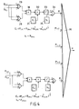
- the simplest method which is used in the device according to FIG. 4 is to determine the instantaneous mechanical power P (t) of the turbo group solely on the basis of the vapor pressures.
- the tap pressures p 1, i , p 2, i , p 1, i + 1 , p 2, i + l etc. see here Fig. 1, j e - because before and after a turbine part, allow with the help of the steam cone law Q i ( p i ) the calculation of the steam flows Q. (t) and thus in a first approximation of the power P i (Q i ).
- the turbine part is to be understood as a section of the turbine between two extraction points for measuring the vapor pressures P 1, i , p 2 i etc.
- both valve groups i.e. the intake and the interception valves
- the intake and the interception valves are brought into a throttle position
- ⁇ h i (t) is the instantaneous enthalpy difference in the case of polytropic expansion and P i, Verl is the power loss of the turbine part in question.
- a state marked with the index IC is to be understood as a reference state from which the values of all relevant state variables are known exactly, e.g. the steady state at 100% load.
- the power loss P i Verl summarizes the leakage, ventilation and friction losses. It can be approximated by a constant without appreciably affecting the accuracy.
- Equation (3) is given the form as a function of P i :
- the first link of (6) is in a known manner by decomposing the radical into and forming the sum or difference of p 1, i and p 2, i in sum-forming elements, ie in an adder 1 and in a subtractor 2, multiplying them in a multiplier and extracting the root in an eraser 4.
- multiplii Zierer 6 Furthermore follows in a multiplii Zierer 6 the multiplication of this value by the constant C i supplied by a read-only memory 5, a multiplication by the difference (P 1, i -p 2, i ) supplied by the subtractor 2 in a multiplier 7, multiplication by p 1, -e i 1, i and p 2, i e 2, i in multipliers 8 and 9, respectively, which factors are supplied to these multipliers via inverters 10 and 11 fed with P 1, i and P 2, i and potentiators 12 and 13 respectively .
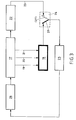
- Fig. 3 shows a block diagram of the control loop of a steam turbine group 17 with the device 18 according to the invention. It is assumed that the vapor pressures are extracted from two turbine parts, the pressure tapping line 19 for the pressure p 1.1 and the pressure tapping line 20 for the Pressure p 2 1 and at the same time for the pressure p 1.2 , which is equal to p 2.1 , see here Fig. 1, and the pressure tapping line 21 is provided for the pressure p 2.2 .
- the generator 22 feeds a power controller 25 with the instantaneous value of the electrical load via a signal line 23 and a switching relay 24 in the normal, correct operating state.
- the control signals from the power controller 25 reach the actuators of the control valve group 26, which adapt the steam supply to the turbo group 17 to the respective requirement. This is the operation in the case of an undisturbed network, in which the contact element 27 of the switching relay 24 is in the position (27) shown in broken lines.
- the control loop corresponds to that shown in FIG. 3.
- the tapping for the measurement of the pressures is expediently carried out on the tapping lines which are present at the beginning and end of the turbine parts for operational reasons.
Landscapes
- Engineering & Computer Science (AREA)
- Mechanical Engineering (AREA)
- General Engineering & Computer Science (AREA)
- Chemical & Material Sciences (AREA)
- Combustion & Propulsion (AREA)
- Control Of Turbines (AREA)
- Dc Machiner (AREA)
- Control Of Electric Motors In General (AREA)
Priority Applications (1)
| Application Number | Priority Date | Filing Date | Title |
|---|---|---|---|
| AT82200541T ATE15526T1 (de) | 1981-07-13 | 1982-05-06 | Einrichtung zur leistungsbestimmung einer turbogruppe waehrend netzstoerungen. |
Applications Claiming Priority (2)
| Application Number | Priority Date | Filing Date | Title |
|---|---|---|---|
| CH456581 | 1981-07-13 | ||
| CH4565/81 | 1981-07-13 |
Publications (2)
| Publication Number | Publication Date |
|---|---|
| EP0070047A1 true EP0070047A1 (fr) | 1983-01-19 |
| EP0070047B1 EP0070047B1 (fr) | 1985-09-11 |
Family
ID=4278453
Family Applications (1)
| Application Number | Title | Priority Date | Filing Date |
|---|---|---|---|
| EP82200541A Expired EP0070047B1 (fr) | 1981-07-13 | 1982-05-06 | Dispositif de détermination de la puissance d'un groupe turbo pendant des dérangements du réseau |
Country Status (4)
| Country | Link |
|---|---|
| US (1) | US4451740A (fr) |
| EP (1) | EP0070047B1 (fr) |
| AT (1) | ATE15526T1 (fr) |
| DE (1) | DE3266140D1 (fr) |
Families Citing this family (2)
| Publication number | Priority date | Publication date | Assignee | Title |
|---|---|---|---|---|
| US5113691A (en) * | 1989-02-26 | 1992-05-19 | Westinghouse Electric Corp. | Turbine-medium flow monitor |
| IT1248448B (it) * | 1990-02-26 | 1995-01-19 | Westinghouse Electric Corp | Metodo e dispositivo per controllare la portata di un fluido in una turbina |
Citations (3)
| Publication number | Priority date | Publication date | Assignee | Title |
|---|---|---|---|---|
| CH371463A (de) * | 1958-09-03 | 1963-08-31 | Sulzer Ag | Verfahren zur Regelung eines aus einem Dampferzeuger und einer Dampfturbine bestehenden Aggregates |
| GB1267590A (en) * | 1968-07-08 | 1972-03-22 | Tokyo Shibaura Electric Co | Automatic extraction and exhaust pressure type turbine control system |
| DE2812820A1 (de) * | 1978-01-31 | 1979-08-02 | Bbc Brown Boveri & Cie | Verfahren und einrichtung zur regelung einer dampfturbine |
Family Cites Families (6)
| Publication number | Priority date | Publication date | Assignee | Title |
|---|---|---|---|---|
| US3657552A (en) * | 1970-06-01 | 1972-04-18 | Robert H Park | Method for employment of fast turbine valving |
| US3999390A (en) * | 1974-04-25 | 1976-12-28 | Westinghouse Electric Corporation | HTGR power plant turbine-generator load control system |
| US4039846A (en) * | 1975-08-18 | 1977-08-02 | Allied Chemical Corporation | Control of a steam-heating power plant |
| CH617494A5 (fr) * | 1975-08-22 | 1980-05-30 | Bbc Brown Boveri & Cie | |
| US4120159A (en) * | 1975-10-22 | 1978-10-17 | Hitachi, Ltd. | Steam turbine control system and method of controlling the ratio of steam flow between under full-arc admission mode and under partial-arc admission mode |
| US4271473A (en) * | 1979-09-27 | 1981-06-02 | Leeds & Northrup Company | Control of parallel operated turbines in cogeneration |
-
1982
- 1982-05-06 EP EP82200541A patent/EP0070047B1/fr not_active Expired
- 1982-05-06 AT AT82200541T patent/ATE15526T1/de not_active IP Right Cessation
- 1982-05-06 DE DE8282200541T patent/DE3266140D1/de not_active Expired
- 1982-07-12 US US06/397,206 patent/US4451740A/en not_active Expired - Fee Related
Patent Citations (3)
| Publication number | Priority date | Publication date | Assignee | Title |
|---|---|---|---|---|
| CH371463A (de) * | 1958-09-03 | 1963-08-31 | Sulzer Ag | Verfahren zur Regelung eines aus einem Dampferzeuger und einer Dampfturbine bestehenden Aggregates |
| GB1267590A (en) * | 1968-07-08 | 1972-03-22 | Tokyo Shibaura Electric Co | Automatic extraction and exhaust pressure type turbine control system |
| DE2812820A1 (de) * | 1978-01-31 | 1979-08-02 | Bbc Brown Boveri & Cie | Verfahren und einrichtung zur regelung einer dampfturbine |
Also Published As
| Publication number | Publication date |
|---|---|
| EP0070047B1 (fr) | 1985-09-11 |
| DE3266140D1 (en) | 1985-10-17 |
| US4451740A (en) | 1984-05-29 |
| ATE15526T1 (de) | 1985-09-15 |
Similar Documents
| Publication | Publication Date | Title |
|---|---|---|
| DE69520934T2 (de) | Methode und system zur optimierung der nützlichkeit einer anlage | |
| DE68922266T2 (de) | Abwärmekessel und Verfahren zu dessen Verwendung. | |
| DE10006455A1 (de) | Verfahren zum Betrieb einer technischen Anlage | |
| EP0509347B1 (fr) | Système pour la surveillance du fonctionnement de turbines à vapeur | |
| DE1763236A1 (de) | Phasendiskriminator | |
| EP0070047B1 (fr) | Dispositif de détermination de la puissance d'un groupe turbo pendant des dérangements du réseau | |
| EP0012961A1 (fr) | Dispositif pour déterminer les défauts influençant la fréquence dans un réseau de distribution d'énergie et application dudit dispositif au réglage de fréquence dans lesdits réseaux | |
| CH679235A5 (fr) | ||
| DE3541148C3 (de) | Verfahren zur Regelung einer Dampfturbine | |
| DE2828645A1 (de) | Einrichtung zur steuerung von mindestens zwei hydraulischen turbinen | |
| EP0098624A1 (fr) | Procédé pour détecter des défauts ou la direction des défauts dans des lignes électriques et moyens pour sa mise en oeuvre | |
| DE1953425A1 (de) | Verfahren und Vorrichtung zur automatischen Regelung der simulierten Neutronenquelle fuer ein Analogreaktimeter | |
| DE2812820A1 (de) | Verfahren und einrichtung zur regelung einer dampfturbine | |
| EP3376026A1 (fr) | Procédé de réglage de la puissance active d'un parc éolien et parc éolien correspondant | |
| EP1892820A1 (fr) | Procédé destiné à calculer le rapport pour la qualité d'un réseau culinaire à commutateur de fréquence | |
| DE2046206A1 (de) | Nachbildung eines Energieversorgungs netzes | |
| DE69824420T2 (de) | Steuer- und Überwachungseinrichtung für die Öffnung oder die Schliessung eines elektrischen Betätigungselementes | |
| DE4443428A1 (de) | Verfahren und Vorrichtung zur Erzeugung eines beliebigen m-phasigen Stromsystems n-ter Ordnung einer umrichtergespeisten Einrichtung | |
| DE10011607A1 (de) | Verfahren und Vorrichtung sowie Computerprogrammprodukt zum Betrieb einer technischen Anlage | |
| DE2103967A1 (de) | Drehzahl Lastregelung fur eine Gasturbine | |
| EP1165951B1 (fr) | Procede de regulation d'une turbine a vapeur a soutirage de vapeur, dispositif de regulation y relatif et turbine a vapeur a soutirage de vapeur | |
| DE102016116207A1 (de) | Energieversorgungsanlage sowie Verfahren und Regelvorrichtung zur Regelung einer Energieversorgungsanlage | |
| DE3336596C2 (de) | Verfahren zum Regeln eines in Kraft-/Wärmekopplung betriebenen Kraftwerkblockes | |
| EP3621169A1 (fr) | Réseau d'îlots et procédé de fonctionnement d'un réseau d'îlots | |
| DE2223647C2 (de) | Verfahren und Schaltungsanordnung zur Überwachung der Erreichung und Überschreitung einer vorgewählten Tangentenrichtlinie der Charakteristik zweier gegenseitig abhängiger, zeitlich veränderlicher Gleichspannungsgrößen |
Legal Events
| Date | Code | Title | Description |
|---|---|---|---|
| PUAI | Public reference made under article 153(3) epc to a published international application that has entered the european phase |
Free format text: ORIGINAL CODE: 0009012 |
|
| AK | Designated contracting states |
Designated state(s): AT BE CH DE FR GB LI SE |
|
| 17P | Request for examination filed |
Effective date: 19830509 |
|
| GRAA | (expected) grant |
Free format text: ORIGINAL CODE: 0009210 |
|
| AK | Designated contracting states |
Designated state(s): AT BE CH DE FR GB LI SE |
|
| REF | Corresponds to: |
Ref document number: 15526 Country of ref document: AT Date of ref document: 19850915 Kind code of ref document: T |
|
| REF | Corresponds to: |
Ref document number: 3266140 Country of ref document: DE Date of ref document: 19851017 |
|
| ET | Fr: translation filed | ||
| PLBE | No opposition filed within time limit |
Free format text: ORIGINAL CODE: 0009261 |
|
| STAA | Information on the status of an ep patent application or granted ep patent |
Free format text: STATUS: NO OPPOSITION FILED WITHIN TIME LIMIT |
|
| 26N | No opposition filed | ||
| PGFP | Annual fee paid to national office [announced via postgrant information from national office to epo] |
Ref country code: GB Payment date: 19930413 Year of fee payment: 12 |
|
| PGFP | Annual fee paid to national office [announced via postgrant information from national office to epo] |
Ref country code: BE Payment date: 19930415 Year of fee payment: 12 |
|
| PGFP | Annual fee paid to national office [announced via postgrant information from national office to epo] |
Ref country code: AT Payment date: 19930420 Year of fee payment: 12 |
|
| PGFP | Annual fee paid to national office [announced via postgrant information from national office to epo] |
Ref country code: FR Payment date: 19930422 Year of fee payment: 12 |
|
| PGFP | Annual fee paid to national office [announced via postgrant information from national office to epo] |
Ref country code: SE Payment date: 19930426 Year of fee payment: 12 |
|
| PGFP | Annual fee paid to national office [announced via postgrant information from national office to epo] |
Ref country code: DE Payment date: 19930706 Year of fee payment: 12 |
|
| PGFP | Annual fee paid to national office [announced via postgrant information from national office to epo] |
Ref country code: CH Payment date: 19930819 Year of fee payment: 12 |
|
| PG25 | Lapsed in a contracting state [announced via postgrant information from national office to epo] |
Ref country code: GB Effective date: 19940506 Ref country code: AT Effective date: 19940506 |
|
| PG25 | Lapsed in a contracting state [announced via postgrant information from national office to epo] |
Ref country code: SE Effective date: 19940507 |
|
| PG25 | Lapsed in a contracting state [announced via postgrant information from national office to epo] |
Ref country code: LI Effective date: 19940531 Ref country code: CH Effective date: 19940531 Ref country code: BE Effective date: 19940531 |
|
| BERE | Be: lapsed |
Owner name: BBC A.G. BROWN BOVERI & CIE Effective date: 19940531 |
|
| GBPC | Gb: european patent ceased through non-payment of renewal fee |
Effective date: 19940506 |
|
| EUG | Se: european patent has lapsed |
Ref document number: 82200541.9 Effective date: 19941210 |
|
| PG25 | Lapsed in a contracting state [announced via postgrant information from national office to epo] |
Ref country code: FR Effective date: 19950131 |
|
| REG | Reference to a national code |
Ref country code: CH Ref legal event code: PL |
|
| PG25 | Lapsed in a contracting state [announced via postgrant information from national office to epo] |
Ref country code: DE Effective date: 19950201 |
|
| EUG | Se: european patent has lapsed |
Ref document number: 82200541.9 |
|
| REG | Reference to a national code |
Ref country code: FR Ref legal event code: ST |