EP0070352A2 - Dispositif pour le découpage en morceaux - Google Patents
Dispositif pour le découpage en morceaux Download PDFInfo
- Publication number
- EP0070352A2 EP0070352A2 EP82101934A EP82101934A EP0070352A2 EP 0070352 A2 EP0070352 A2 EP 0070352A2 EP 82101934 A EP82101934 A EP 82101934A EP 82101934 A EP82101934 A EP 82101934A EP 0070352 A2 EP0070352 A2 EP 0070352A2
- Authority
- EP
- European Patent Office
- Prior art keywords
- cutting
- workpiece holder
- axis
- cutting disc
- frame
- Prior art date
- Legal status (The legal status is an assumption and is not a legal conclusion. Google has not performed a legal analysis and makes no representation as to the accuracy of the status listed.)
- Ceased
Links
Images


Classifications
-
- B—PERFORMING OPERATIONS; TRANSPORTING
- B28—WORKING CEMENT, CLAY, OR STONE
- B28D—WORKING STONE OR STONE-LIKE MATERIALS
- B28D1/00—Working stone or stone-like materials, e.g. brick, concrete or glass, not provided for elsewhere; Machines, devices, tools therefor
- B28D1/02—Working stone or stone-like materials, e.g. brick, concrete or glass, not provided for elsewhere; Machines, devices, tools therefor by sawing
- B28D1/025—Use, recovery or regeneration of abrasive mediums
-
- B—PERFORMING OPERATIONS; TRANSPORTING
- B23—MACHINE TOOLS; METAL-WORKING NOT OTHERWISE PROVIDED FOR
- B23D—PLANING; SLOTTING; SHEARING; BROACHING; SAWING; FILING; SCRAPING; LIKE OPERATIONS FOR WORKING METAL BY REMOVING MATERIAL, NOT OTHERWISE PROVIDED FOR
- B23D45/00—Sawing machines or sawing devices with circular saw blades or with friction saw discs
- B23D45/02—Sawing machines or sawing devices with circular saw blades or with friction saw discs with a circular saw blade or the stock mounted on a carriage
- B23D45/021—Sawing machines or sawing devices with circular saw blades or with friction saw discs with a circular saw blade or the stock mounted on a carriage with the saw blade mounted on a carriage
- B23D45/024—Sawing machines or sawing devices with circular saw blades or with friction saw discs with a circular saw blade or the stock mounted on a carriage with the saw blade mounted on a carriage the saw blade being adjustable according to depth or angle of cut
-
- B—PERFORMING OPERATIONS; TRANSPORTING
- B23—MACHINE TOOLS; METAL-WORKING NOT OTHERWISE PROVIDED FOR
- B23D—PLANING; SLOTTING; SHEARING; BROACHING; SAWING; FILING; SCRAPING; LIKE OPERATIONS FOR WORKING METAL BY REMOVING MATERIAL, NOT OTHERWISE PROVIDED FOR
- B23D47/00—Sawing machines or sawing devices working with circular saw blades, characterised only by constructional features of particular parts
- B23D47/128—Sawing machines or sawing devices working with circular saw blades, characterised only by constructional features of particular parts of means to position the saw blade at a specified angle when adjusting about an axis parallel to the work support surface
Definitions
- the invention relates to a comminution device for workpieces made of metal, concrete and the like, hard materials for cutting with the aid of a rotating cutting disc of a motor-driven cutting device, in which a workpiece holder is arranged on a frame, and a feed guide for support that extends with its feed axis in the cutting direction is mounted and in which the separating device is mounted on the support in a tracking for the cutting depth, which is oriented with its tracking axis crossed to the feed axis.
- the invention is characterized in that when separating the feed axis is inclined at an angle of 30 to 60 °, preferably 45 °, with respect to the horizontal base of the frame, that the cutting disc is driven all the way down in the cutting cut and that a water pan is arranged on the frame below the path of the cutting disc in the downward extension of the cutting cut, which is open at the top.
- the abrasion with the liquid is sprayed obliquely downwards in the tangential extension of the respective separating peripheral section of the cutting disc and can be collected there safely and without great effort from the water filling of the water tub.
- the frame is enclosed by a dust-tight cage, which extends on both sides from the workpiece holder and above the workpiece holder, by means of a sliding hood closable opening and dust extraction.
- dustproof does not mean airtight, it is sufficient to have an air seal that prevents air and therefore dust from escaping from the cage in an uncontrolled manner.
- the proposed deduction maintains a negative pressure inside the cage, which prevents air or dust from escaping uncontrollably due to leaks in the cage.
- the tracking axis can be vertical or horizontal, intermediate positions are also possible.
- the tracking axis is preferably perpendicular to the feed axis and forms a vertically oriented guide plane for the center plane of the cutting disc with respect to the horizontal base of the frame. You can then train the feed guide and the tracking, as far as the mutual axis orientation is concerned, in a known manner and only have to arrange them overall with the desired inclination within the frame, so that one can largely rely on known construction elements in this further development.
- the workpiece holder is also appropriately oriented, in that it has a work table which extends at an angle to the base surface with the same inclination as the feed axis.
- the workpieces to be shredded are also very heavy workpieces made of concrete, metal and / or the like, which, when they lie on the workpiece holder and are secured against slipping, are adequately fixed by gravity for the separating process, so that no additional Brackets or the like is required.
- a support is provided at the downward end of the workpiece holder for a workpiece lying down on the workpiece holder. An overlying workpiece is then moved towards the support and is therefore fixed due to gravity. When disconnecting it is due to the intended direction of rotation of the cutting disc, if any, then pushed in downward direction, so that it lung secure S medium- during the separation process, may adjacent to this support, abandoned. It is recommended that the support has a slot for the entry of the cutting disc in the extension of the cutting cut.
- a mounting plate which extends at an angle to the base with the inclination of the feed axis, which is rotatably mounted on the workpiece mounting around a mounting axis perpendicular to the work table, which has a support rim around it that serves as a support and has several different rotational positions of the mounting plate for corresponding slots has the entry of the cutting disc on +.
- the workpiece holder is displaceably and lockably mounted in two slide rails, which slide rails extend perpendicular to the guide plane, are arranged parallel next to one another in a slide plane which is inclined with the inclination of the feed axis extends to the stand area.
- the workpiece holder If you move the workpiece holder after a separating cut has been made, the workpiece moves and gets into a new cutting position. On the slide rails, the workpiece holder together with the workpiece can also be pulled out of the area below the separating device, making the workpiece holder easily accessible for unloading or reloading.
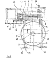
- 1 and 2 denotes a frame which is placed on a horizontal floor 3 with a horizontal base 2.
- a motor-operated separating device 4 is mounted on the frame 1 in a feed guide 5 so that it can be pushed back and forth in the direction of the double arrow 27.
- the feed guide 5 consists of two slide rods 6 and 7 which are axially parallel to one another and a drive spindle 8 which is axially parallel to it and which is rotatably mounted and can be driven by a drive motor 9.
- the drive spindle 8 is screwed into a threaded hole of a support 1 0, on which the separating device 4 is mounted so that it can move back and forth in the direction of the double arrow 12 with a guide 11.
- the tracking 11 consists of two mutually coaxial slide rails 13, 14 and a coaxial threaded spindle 15 which can be driven by a drive motor 16 around its axis and is screwed into a threaded hole in the housing of a drive motor 17.
- the separating device 4 has a cutting disc 18 which is plugged onto the stub shaft of the drive motor 17 and is covered obliquely upwards by a protective cover 19 and is exposed obliquely downwards.
- the cutting disc 18 is driven all around in the direction of the arrow 20 and can be guided by the feed guide 5 in the direction of the feed axis 21 along the desired cutting cut and by the tracking tion 11 are tracked in the direction of the tracking axis 22 in the depth of cut.
- the two axes 21, 22 are perpendicular to one another and span a parallel plane to the guide plane 32, which extends in the central plane of the cutting disc 18, that is to say parallel to the plane of the drawing in FIG. 1 .
- the abrasion is collected by a water trough 25 which is arranged at the foot of the frame 1 and which is open at the top and which extends in a downward extension of the cutting cut or the abrasion cone below the path of the cutting disc 18 with tolerance on all sides.
- the edge of the water trough 25 is higher on the part shown on the right, in order to prevent abrasion from splashing over the edge there.
- the same purpose is also served by a tongue 26 which is articulated about an axis perpendicular to the plane of FIG. 1 on the protective cover 19 and extends downward and extends over the entire width of the tub and plunges into it.
- two slide rails 30, 31 extend perpendicular to the guide plane 32, which, together with a front end part 34, form a cantilever of the frame.
- the axes 36, 37 of the slide rails define a slide plane 38, which extends perpendicular to the guide plane 32 and is inclined at an angle to the standing surface 2, with the same angle 23 as the feed axis 2 1 .
- a workpiece holder 40 is displaceable on these slide rails in the manner of a slide guide.
- a threaded spindle 52 which can be driven by a motor 39 and is screwed into a threaded hole in the workpiece holder, serves to move the workpiece holder.
- the workpiece holder 40 can be moved into a functional position outlined in FIG. 1 by the dash-dotted line 42, in which it is located below the effective range of the cutting disc 18, and from there into a disengaged loading and unloading position, in which it is drawn in a solid line in FIG. 2 is. In the area of the functional position, the workpiece holder 40 can be shifted in small steps in accordance with the laterally offset separating cuts.
- the top of the workpiece holder 40 is designed as a work table 44 which, like the sliding plane 38, is inclined at an angle.
- a workpiece, which is to be separated, can be fastened to the work table with the help of clips, not shown.
- a workpiece 51 to be separated is pushed down on the sloping mounting plate up to the stop against the support edge 48. In this position, its weight is sufficient to hold it in place.
- the workpiece is then traversed by the cutting disc, starting from the top right in FIG. 1, to the bottom left. This is repeated until the workpiece is cut.
- the cutting disc is immersed in the slot at the lowest point of the mounting plate.
- 101 denotes a frame which is placed on a horizontal floor 103 with a horizontal standing surface 102.
- a motor-driven separating device 104 is mounted on the frame 101 in a feed guide 105 so that it can be pushed back and forth in the direction of the double arrow 127.
- a support for the separating device 104 is designated by 110, which is mounted so that it can move back and forth in a track 11 in the direction of the double arrow 112 along the track axis 1 22.
- the drive motor 116 is used to move the cutting device along the feed guide 1 05 and the drive motor 153 is used to move it along the track.
- the cutting disc 118 which is covered at the top by a protective cover 119, is driven in a rotating manner in the direction of the arrow 120 by a drive motor 117.
- the feed axis 121 extends at an acute angle 123 of approximately 45 ° relative to the standing surface 102, so that the abrasion occurring during separation is injected into the open 'water pan 125 arranged at the base of the frame 101.
- 140 denotes a workpiece holder with which a workpiece 151, which is to be cut, can be stored on a work table 1 44.
- the work table 144 has a slot 154 in which the cutting disc 118 fits.
- the water pan 125 is filled up to the water level 160 determined by the overflow 1 58 and water constantly flows along the channel 155 into the water pan.
- the water in the channel 15 5 precipitates the grinding dust accumulating there.
- Spraying sanding dust is caught in the water filling of the water tub 125, so that finally all sanding dust in the water tub 125th is put down.
- the grinding dust sump that forms there can be removed by means of an emptying nozzle 161 attached to the bottom of the water trough 125 and leading to the outside.
- the washing water is also radioactively contaminated and must be decontaminated. This can happen ekontaminier overlooked in the standing of such work areas generally available D.
- the used water can also be recirculated, for example as indicated in FIG. 6.
- 170 denotes the separating device from FIGS. 3 to 5, from which the water drawn off at the overflow 158 and the nozzle 161 reaches a water treatment system 172 via a lifting pump 171. There, the solids are separated and reach a collecting container 173. Via a lifting pump 174, the treated water passes through a filter system 175 and a check valve 176 to a cooling device 177 and from there via the water inlet 156 and 157 to the separating device 170.
- the cooling device 177 can be the oil cooler of a hydraulic system 17 8, which is used to supply the motors designed as hydraulic power units and hoists of the separating device with pressurized oil.
- an exhaust system with exhaust filter is referred to, which is connected to an exhaust 181 of the separation device.
- the frame 101 is accommodated in a dust-tight cage 1 82, from which the mentioned deduction 1 81 originates.
- the trigger 181 opposite in the cage wall is an opening 15 9 with a gravity-loaded supply air flap 1 83, through which, in conjunction with the trigger 181, it can be ensured that a negative pressure of approximately 3 to 15 milli within the cage 182 cash can be maintained. In this way it is ensured that no air and therefore no dust can escape uncontrolled due to leaks in the cage.
- a viewing window 184 is embedded in the cage 182, which consists of opaque material.
- An opening 179 which extends on both sides and above the workpiece holder 140, is provided in the cage and can be closed by a sliding hood 185.
- the sliding hood 185 is drawn in FIG. 3 in the closed position and in FIG. 5 in the open position.
- the cutting device can be pivoted about an axis 187 parallel to the cutting disc axis 186 and in the immediate vicinity of the cutting disc axis, namely from the functional position shown in FIG. 3 into a swiveled-up rest position shown in FIG. 5, in which it releases the space above the work table 144 .
- the swiveled-up separating device also finds space within the cage 182. When the separating device is swiveled, the guide 111 and the feed guide 105 as well as the motors for driving these guides and the cutting disk move.
- a hydraulic cylinder 188 is provided for pivoting the separating device.
Landscapes
- Engineering & Computer Science (AREA)
- Mechanical Engineering (AREA)
- Mining & Mineral Resources (AREA)
- Crushing And Pulverization Processes (AREA)
- Processing Of Solid Wastes (AREA)
- Processing Of Stones Or Stones Resemblance Materials (AREA)
Priority Applications (1)
| Application Number | Priority Date | Filing Date | Title |
|---|---|---|---|
| PL23736482A PL237364A1 (en) | 1981-07-16 | 1982-07-08 | Apparatus for crushing articles made of hard materials |
Applications Claiming Priority (2)
| Application Number | Priority Date | Filing Date | Title |
|---|---|---|---|
| DE3128087 | 1981-07-16 | ||
| DE19813128087 DE3128087A1 (de) | 1981-07-16 | 1981-07-16 | Zerkleinerungsvorrichtung |
Publications (2)
| Publication Number | Publication Date |
|---|---|
| EP0070352A2 true EP0070352A2 (fr) | 1983-01-26 |
| EP0070352A3 EP0070352A3 (fr) | 1983-09-21 |
Family
ID=6137035
Family Applications (1)
| Application Number | Title | Priority Date | Filing Date |
|---|---|---|---|
| EP82101934A Ceased EP0070352A3 (fr) | 1981-07-16 | 1982-03-11 | Dispositif pour le découpage en morceaux |
Country Status (2)
| Country | Link |
|---|---|
| EP (1) | EP0070352A3 (fr) |
| DE (1) | DE3128087A1 (fr) |
Cited By (2)
| Publication number | Priority date | Publication date | Assignee | Title |
|---|---|---|---|---|
| EP0507219A3 (en) * | 1991-03-30 | 1993-04-28 | Hoestemberghe & Kluetsch Gmbh | Grinding cut-off machine for cutting plates |
| CN106141278A (zh) * | 2016-08-31 | 2016-11-23 | 江苏高德液压机械有限公司 | 立式剪切机 |
Family Cites Families (3)
| Publication number | Priority date | Publication date | Assignee | Title |
|---|---|---|---|---|
| US2009859A (en) * | 1931-06-30 | 1935-07-30 | American Chain & Cable Co | Abrasive cut-off machine |
| US2107566A (en) * | 1936-03-09 | 1938-02-08 | Whitney Metal Tool Company | Cut-off machine |
| CH244665A (de) * | 1945-04-28 | 1946-09-30 | Blaesi & Co F | Trennschleifmaschine. |
-
1981
- 1981-07-16 DE DE19813128087 patent/DE3128087A1/de not_active Withdrawn
-
1982
- 1982-03-11 EP EP82101934A patent/EP0070352A3/fr not_active Ceased
Cited By (3)
| Publication number | Priority date | Publication date | Assignee | Title |
|---|---|---|---|---|
| EP0507219A3 (en) * | 1991-03-30 | 1993-04-28 | Hoestemberghe & Kluetsch Gmbh | Grinding cut-off machine for cutting plates |
| CN106141278A (zh) * | 2016-08-31 | 2016-11-23 | 江苏高德液压机械有限公司 | 立式剪切机 |
| CN106141278B (zh) * | 2016-08-31 | 2018-03-30 | 江苏高德液压机械有限公司 | 立式剪切机 |
Also Published As
| Publication number | Publication date |
|---|---|
| EP0070352A3 (fr) | 1983-09-21 |
| DE3128087A1 (de) | 1983-02-03 |
Similar Documents
| Publication | Publication Date | Title |
|---|---|---|
| DE2913524C2 (de) | Verfahren und Einrichtung zur Behandlung von metallurgischer Schlacke, insbesondere Hochofenschlacke | |
| DE3532377C2 (fr) | ||
| DE69509400T2 (de) | Vorrichtung zum manuellen sortieren von abfällen | |
| DE2701872A1 (de) | Vorrichtung zum trennen von festkoerperteilchen von fluessigkeiten | |
| DE8119452U1 (de) | Vorrichtung zum Zerkleinern von Werkstücken | |
| DE3142868A1 (de) | Fliehkraftbearbeitungsmaschine | |
| DE2923335A1 (de) | Vorrichtung zum abscheiden von festen koerpern aus einer fluessigkeit | |
| DE19932416A1 (de) | Vorrichtung zum Entwässern von Schlamm | |
| EP0750966B1 (fr) | Récipient collecteur avec pompe | |
| DE1953741C3 (de) | Vorrichtung zum Trennen von Festteilchen wie z.B. Kunststoffgranulaten und Flüssigkeit | |
| EP0070352A2 (fr) | Dispositif pour le découpage en morceaux | |
| DE60310248T2 (de) | Verteiler für rotierendes filter und rotierendes filter mit einem solchen verteiler | |
| DE4038253A1 (de) | Fliehkraftbearbeitungsmaschine | |
| EP0134878A2 (fr) | Dispositif de traitement des émulsions épuisées, des solutions et des eaux d'égout industrielles etc. | |
| DE8206757U1 (de) | Zerkleinerungsvorrichtung | |
| DE4209297C2 (de) | Behandlungseinrichtung für den Reinraumbereich | |
| DE3939426C2 (de) | Vorrichtung zum Abtrennen von Feststoffen aus einer Flüssigkeit oder zum Abtrennen von aus Emulsionen ausgefällten Sedimenten | |
| EP0180701B1 (fr) | Procédé et dispositif pour séparer des corps étrangers tels que pierres, gravier et sable de plantes sarclées, en particulier de betteraves à sucre | |
| DE8120851U1 (de) | Zerkleinerungsvorrichtung | |
| DE3724773C1 (en) | Method for opening and emptying drinks cans | |
| AT371374B (de) | Vorrichtung zum mischen, granulieren oder ueberziehen von pulvern oder koernigen substanzen mit einem kondensator zur loesungsmittel -abscheidung und - rueckgewinnung | |
| DE3316713C2 (de) | Vibrationsgleitschleifmaschine | |
| DE19512584C1 (de) | Schneidsiebvorrichtung | |
| DE675811C (de) | Vorrichtung zum Impraegnieren von Braunkohlenbriketts | |
| DE2813705A1 (de) | Vorrichtung zum sandstrahlen von werkstuecken |
Legal Events
| Date | Code | Title | Description |
|---|---|---|---|
| PUAI | Public reference made under article 153(3) epc to a published international application that has entered the european phase |
Free format text: ORIGINAL CODE: 0009012 |
|
| AK | Designated contracting states |
Designated state(s): AT BE CH DE FR GB IT LI NL SE |
|
| PUAL | Search report despatched |
Free format text: ORIGINAL CODE: 0009013 |
|
| 17P | Request for examination filed |
Effective date: 19830618 |
|
| AK | Designated contracting states |
Designated state(s): AT BE CH DE FR GB IT LI NL SE |
|
| RHK1 | Main classification (correction) |
Ipc: B24B 27/06 |
|
| STAA | Information on the status of an ep patent application or granted ep patent |
Free format text: STATUS: THE APPLICATION HAS BEEN REFUSED |
|
| 18R | Application refused |
Effective date: 19850408 |
|
| RIN1 | Information on inventor provided before grant (corrected) |
Inventor name: KUPFER, KARLHEINZ Inventor name: KELLER, WOLFGANG |