EP0070387A2 - Verfahren und Gerät zur Erzeugung von eines geräuschlos gleitenden Blockcodes für einen Kanal mit 2/3 Verhältnis - Google Patents
Verfahren und Gerät zur Erzeugung von eines geräuschlos gleitenden Blockcodes für einen Kanal mit 2/3 Verhältnis Download PDFInfo
- Publication number
- EP0070387A2 EP0070387A2 EP82105020A EP82105020A EP0070387A2 EP 0070387 A2 EP0070387 A2 EP 0070387A2 EP 82105020 A EP82105020 A EP 82105020A EP 82105020 A EP82105020 A EP 82105020A EP 0070387 A2 EP0070387 A2 EP 0070387A2
- Authority
- EP
- European Patent Office
- Prior art keywords
- bits
- encoder
- channel
- state
- input
- Prior art date
- Legal status (The legal status is an assumption and is not a legal conclusion. Google has not performed a legal analysis and makes no representation as to the accuracy of the status listed.)
- Granted
Links
Images




Classifications
-
- G—PHYSICS
- G06—COMPUTING OR CALCULATING; COUNTING
- G06T—IMAGE DATA PROCESSING OR GENERATION, IN GENERAL
- G06T9/00—Image coding
- G06T9/005—Statistical coding, e.g. Huffman, run length coding
-
- G—PHYSICS
- G11—INFORMATION STORAGE
- G11B—INFORMATION STORAGE BASED ON RELATIVE MOVEMENT BETWEEN RECORD CARRIER AND TRANSDUCER
- G11B20/00—Signal processing not specific to the method of recording or reproducing; Circuits therefor
- G11B20/10—Digital recording or reproducing
- G11B20/14—Digital recording or reproducing using self-clocking codes
- G11B20/1403—Digital recording or reproducing using self-clocking codes characterised by the use of two levels
- G11B20/1423—Code representation depending on subsequent bits, e.g. delay modulation, double density code, Miller code
- G11B20/1426—Code representation depending on subsequent bits, e.g. delay modulation, double density code, Miller code conversion to or from block codes or representations thereof
Definitions
- This invention describes a sequential coding system which converts unconstrained data into a constrained format in an invertible manner.
- the described invention is particularly useful in dynamic memory systems.
- Raising the coding efficiency or rate at the expense of decoding look-ahead generally results in increasing the error propagation. That is, a single bit error introduced in the code stream will cause a certain number of subsequent bits to also be erroneous before the coding algorithm becomes self-correcting. It is always desirable to minimize error propagation. It has been found that a coding rate of 2/3 is optimal for the (1,7) code.
- U.S. Patent 3,689,899 to P. A. Franaszek discloses two possible (d,k) codes (1,8) and (2,7).
- the potential data codes are variable length, fixed rate state independent block codes.
- the coding rate of the (1,8) code is 2/3 and its code dictionary consists of 16 code words whose lengths vary from 3 to 9 bits, in multiples of 3.
- the (2,7) code has a coding rate of 1/2 and its dictionary consists of seven words with lengths varying from 2 bits to 8 bits, in multiples of 2.
- the (1,7) code constructed by Franaszek has.a finite look-ahead encoder and a variable length decoder.
- the encoder converts two data bits into 3 constrained bits by employing look-ahead of two additional data bits.
- the coded output is thus a function of the present two and the future two data bits.
- the decoder maps 3 constrained bits into two data bits as a function of the present channel state and for a particular channel state this dependence extends to the previous channel state.
- the error propagation of this code is 5 bits.
- the codes constructed by Horiguchi et al are variable length fixed rate codes. The error propagation of their code is 6 bits.
- Another advantage of this invention is the existence of reset data blocks which reset the finite state machine encoder into known fixed states which are independent of its initial state. This feature is absent in the prior art.
- the objects of the present invention are met by using a novel sequential algorithm (described subsequently) for mapping unconstrained data-into a constrained format in an invertible manner.
- this algorithm specifies finite state machine encoders and decoders that implement such maps.
- the decoder requires a lookahead of two channel symbols, each of which consists of 3 bits.
- the hardware embodiment of the encoder and decoder as described in FIGS. 3 and 7 is extremely efficient both in terms of the total quantity of logic circuitry required and in terms of the maximum speed that it can achieve.
- the herein disclosed method involves a mathematically provable algorithm that is used to generate a (1,7) data code as applied to the (1,7) - channel.
- the algorithm is described in an article by R. L. Adler and B. Marcus, "Topological Entropy and Equivalence of Dynamical Systems", Mem. A.M.S. 219 (1979).
- the algorithm input is the state transition matrix T of the constrained (1,7) channel
- the state transition matrix T specifies the admissible concatenations of the binary blocks ⁇ a,b,c,e,f ⁇ which label its rows and columns (Note: the letter d is omitted since it would correspond to the nonadmissible block 011 in the adopted letter-binary block correspondence).
- a description of the matrix T which is more suitable for the algorithm described is a successor table.
- the coding rate is determined by the channel capacity C T which is given as the basis two algorithm of the maximum eigenvalue ⁇ T or the matrix T. This number is obtained generally from a procedure that computes eigenvalues of 0-1 matrices.
- the second input to the coding algorithm is a right approximating eigenvector r that satisfies Tr > r
- this vector is obtained as the solution of an integer programming problem.
- the algorithm splits the channel states ⁇ a,b,c,e,f ⁇ according to the components of the vector r in the appropriate order as follows ( ⁇ denotes splitting): (Note: The labeling used above simplifies the complexity of the encoding device).
- This table contains all the information required in the construction of both encoder and decoder. We rewrite it in a more suitable format.
- the decoder construction is based on the particular structure of the table in FIG. 4. We observe the following properties:
- the decoder is specified by Boolean equations derived from the two Boolean tables describing the next state and output functions.
- the decoder thus becomes channel state independent.
- the hardware implementation of the Boolean equations for s0 and sl is described in FIG. 7.
- this error will not be propagated by more than two additional channel symbols. Since a channel symbol corresponds to two data bits, the error propagation of the decoder does not exceed 6 data bits. The actual error propagation is 5 bits.
- the sliding block codes described are-sequential schemes which employ look ahead at the decoder. These codes differ from the bounded delay codes of P. Franaszek which employ look ahead at the encoder.
- the source block 10 represents a source of binary data which is supplied 2 bits at a time to the encoder 12.
- the output of the encoder is a sequence generated by catenations of 3 bit words in a constrained list of size 5.
- the coded sequence is matched to the characteristics of the channel. As described previously, it is assumed that the channel in the present embodiment would be a magnetic recording medium such as a magnetic disc, tape, or the like. However, as will be appreciated by those skilled in the art, the channel could also be a transmission medium, etc.
- the encoded (or constrained) data is supplied 3 bits at a time to the decoder which, as will be well understood, performs the reverse function of the encoder to produce the sequence of 2 bit unconstrained data groups or segments.
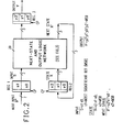
- FIG. 2 a functional block diagram of the encoder is set forth.
- the encoder as is apparent from the drawing comprises 3 registers 1, 2 and 3, and a block denoted as the next state and output logic network.
- This block embodies a finite state machine consisting of a minimum amount of a conventional logic circuitry which is shown in detail in FIG. 3.
- register 1 is utilized to store the data input vector S comprising bits s0 and sl.
- Register 2 is utilized to store the state vector X which comprises bits xO, xl, x2.
- register 3 is utilized to store the constrained channel vector Y' comprising bits y0', yl', y2'.
- the data flow within the encoder may be clearly seen from FIG. 2 wherein the input vector S consisting of two unconstrained data bits, enters the encoder logic network 20 in the upper left-hand corner. Concurrently, the state vector X, comprising 3 bits enters the lower left-hand corner as indicated.
- the output from the encoder network 20 comprises the actual output channel bits Y' and the next state bits X'.
- FIG. 3 The data flow and details of the next state and output logic network 20 are clearly shown in FIG. 3.
- the simplicity of the design of the hardware embodiment of the present encoder is evident in this figure.
- a total of ten conventional logic circuits perform the entire encoding operation.
- the dramatic savings in circuitry may be readily seen by contrasting the present circuitry with, for example, the circuitry required to perform the encoding operation in the prior art.
- the ten logic circuits specifically required are 2 inverters 22 and 24, 2 nand circuits 26 and 28, 1 nor circuit 30,and 5 and circuits 32, 34, 36, 38 and 40.
- the operation of the logic circuits in the wiring of the particular bit lines for the two bit S vector and the 3 bit X vector are clearly labeled.
- the specific bit lines for the two outputs-comprising the Y' vector and the X' vector are clearly labeled.
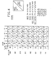
- the state machine transition table for the herein disclosed (1,7) encoder having a coding rate 2/3 is illustrated.
- This table specifies every possible combination of inputs (S and X) to the encoder and similarly specifies the precise outputs (Y' and X') which will be produced for any given set of inputs.
- the left hand column defines the possible state vector entries into the table and thus all of the particular 3 bit state vector X configurations possible. Across the top of the table the possible bit configurations of the 2 bit input vector S are specified.
- each of the table entries specifies the next state X' and the lower diagonal specifies the next output vector Y'.
- the particular bit configuration for both inputs is specifically set forth in the row and column headings and the bit configuration for the next output vector is specified in the table at the bottom of the 'legend' which accompanies the figure.
- the output vector Y' for those particular inputs would be 101.
- the significant entries or contents of the table are the actual binary bit configurations shown. Stated differently, the significant contents of the table of FIG. 4 are the sequences of "l's" and "0's". Thus assuming an X vector input of 001 and an S vector input of 10 , the significant information in the table is that a next state vector X' of 001 would be produced and a next output vector Y' 001 would be produced. Whether this information is in row 1 or column 1 of the table is irrelevant.
- the (1,7) encoder state diagram of FIG. 5 is included to illustrate graphically the state transitions which may occur within the encoder.
- Each of the numbered circles or nodes represents a particular coding state which represents the particular binary configuration specified in table 4.
- node 4 would correspond to a coding state wherein the state vector X has the binary configuration 100.
- the 4 arrows leaving node 4 are labeled 0/a, I/a, 2/a, and 3/a. It will be noted that these arrows point to nodes 0, 1, 2 and 3 respectively.
- the numbers on the arrows have the following significance.
- the 2 in the 2/a arrow indicates that data vector S is 10 (as shown in col. 2 of FIG.
- next output vector Y' is 000 (from the "legend" table in FIG. 4).
- next state vector X' is represented by node 1 which implies the binary value of 001. It is only coincidental that certain of the numbers defining the arrows appear to point to the same node as specified in the S vector labels of FIG. 4.
- nodes 5, 6 and 7 map to other nodes but that none of the nodes 0 - 4 will map into the nodes 5, 6 or 7.
- nodes 5, 6 or 7 could be used as initializing state vectors, however, the remaining operations would occur completely within those portions of the table indicated by the state nodes 0 through 4.
- FIG. 6 a functional block diagram of the present (1,7) decoder is set forth. It will be noted that this figure is quite similar to FIG. 2 of the encoder, however, with the decoding operation it is not necessary to generate and retain the state information.
- the decoder is solely a function of the current channel symbol and the future two channel symbols. Thus, unlike the encoder, it does not possess an internal state that has to be computed and fed back to its input.
- Registers 4, 5 and 6 respectively store as indicated, various groups of channel bits.
- Register 4 contains the next-next channel symbol Y"'.
- Register 5 contains the 3 bits of the next channel symbol Y" and register 6 contains the single bit y0' of the current channel symbol Y'. As is apparent, these bits are gated directly into the decoder logic network shown in FIG. 7 to produce the two desired output data bits s0 and sl.
- the encoder/decoder method and apparatus of the present invention has particular utility in dynamic recording systems, such as magnetic recording channels wherein a particular (1,7) run length limited code provides superior recording results in the magnetic channel as is well known in the art.
- the hardware is extremely efficient in that an absolute minimum of circuitry is required and, as will be appreciated from the logical schematic diagrams, a minimum number of levels are required in the logic circuitry, thus enabling it to operate very rapidly.
Landscapes
- Engineering & Computer Science (AREA)
- Multimedia (AREA)
- Physics & Mathematics (AREA)
- General Physics & Mathematics (AREA)
- Theoretical Computer Science (AREA)
- Signal Processing (AREA)
- Error Detection And Correction (AREA)
- Signal Processing For Digital Recording And Reproducing (AREA)
- Compression, Expansion, Code Conversion, And Decoders (AREA)
- Dc Digital Transmission (AREA)
Applications Claiming Priority (2)
| Application Number | Priority Date | Filing Date | Title |
|---|---|---|---|
| US06/283,758 US4413251A (en) | 1981-07-16 | 1981-07-16 | Method and apparatus for generating a noiseless sliding block code for a (1,7) channel with rate 2/3 |
| US283758 | 2002-10-30 |
Publications (3)
| Publication Number | Publication Date |
|---|---|
| EP0070387A2 true EP0070387A2 (de) | 1983-01-26 |
| EP0070387A3 EP0070387A3 (en) | 1985-07-03 |
| EP0070387B1 EP0070387B1 (de) | 1987-09-09 |
Family
ID=23087432
Family Applications (1)
| Application Number | Title | Priority Date | Filing Date |
|---|---|---|---|
| EP82105020A Expired EP0070387B1 (de) | 1981-07-16 | 1982-06-08 | Verfahren und Gerät zur Erzeugung von eines geräuschlos gleitenden Blockcodes für einen Kanal mit 2/3 Verhältnis |
Country Status (4)
| Country | Link |
|---|---|
| US (1) | US4413251A (de) |
| EP (1) | EP0070387B1 (de) |
| JP (1) | JPS5813020A (de) |
| DE (1) | DE3277248D1 (de) |
Cited By (12)
| Publication number | Priority date | Publication date | Assignee | Title |
|---|---|---|---|---|
| EP0083412B1 (de) * | 1981-12-31 | 1988-03-30 | International Business Machines Corporation | Verfahren und Vorrichtung zum Codieren von Daten |
| EP0249106A3 (en) * | 1986-06-13 | 1988-08-10 | International Business Machines Corporation | Asymmetric rll coding |
| EP0209671A3 (en) * | 1985-06-13 | 1989-04-26 | International Business Machines Corporation | Run length limited encoder and its method of operation |
| EP0205009A3 (en) * | 1985-06-13 | 1989-05-03 | International Business Machines Corporation | System for encoding a data stream into a run length limited symbol string |
| EP0271317A3 (en) * | 1986-12-08 | 1989-11-15 | Fujitsu Limited | Data modulation and demodulation system for magnetic recording system |
| EP0333324A3 (de) * | 1988-03-18 | 1992-07-22 | International Business Machines Corporation | Angepasste Null-Spektral-Trellis-Koden für Partial-Response-Kanäle |
| EP0333321A3 (de) * | 1988-03-18 | 1992-07-22 | International Business Machines Corporation | Modulationskodierung gerader Marken |
| EP0467678A3 (en) * | 1990-07-18 | 1992-10-14 | Kabushiki Kaisha Toshiba | Variable length coding apparatus and variable length decoding apparatus |
| GB2260238A (en) * | 1991-10-04 | 1993-04-07 | Sony Broadcast & Communication | Data encoder |
| US5321397A (en) * | 1991-10-04 | 1994-06-14 | Sony United Kingdom Limited | Data encoder for producing and storing info runlength value, bit length values and encoded words from input data values |
| SG89269A1 (en) * | 1997-11-06 | 2002-06-18 | Caleb Technology Corp | Magnetic recording encoder system for a (1,7) channel having a 2/3 coding rate |
| EP1988636A1 (de) * | 2007-05-03 | 2008-11-05 | Deutsche Thomson OHG | Verfahren und Vorrichtung zur Kanalkodierung und -dekodierung |
Families Citing this family (69)
| Publication number | Priority date | Publication date | Assignee | Title |
|---|---|---|---|---|
| JPS57195308A (en) * | 1981-05-26 | 1982-12-01 | Sony Corp | Block coding method |
| NL8203575A (nl) * | 1982-09-15 | 1984-04-02 | Philips Nv | Werkwijze voor het coderen van een stroom van databits, inrichting voor het uitvoeren van de werkwijze en inrichting voor het decoderen van een stroom databits. |
| US4484176A (en) * | 1982-11-24 | 1984-11-20 | Storage Technology Corporation | Run length limited data encoder |
| JPS6096746A (ja) * | 1983-10-28 | 1985-05-30 | Mitsui Alum Kogyo Kk | 複合材料とその製造方法 |
| NL8402444A (nl) * | 1984-01-20 | 1986-03-03 | Philips Nv | Werkwijze voor het overdragen van informatie, codeerinrichting voor toepassing in de werkwijze en decodeerinrichting voor toepassing in de werkwijze. |
| JPS61227430A (ja) * | 1985-04-01 | 1986-10-09 | Matsushita Electric Ind Co Ltd | 符号変換装置 |
| US4684921A (en) * | 1985-06-13 | 1987-08-04 | International Business Machines Corporation | RLL (1,7) encoder with single state bit |
| US4737765A (en) * | 1986-10-22 | 1988-04-12 | Magnetic Peripherals Inc. | 2,7 Code decoder with no more than 3 bits error propagation |
| DE3825960A1 (de) * | 1987-09-01 | 1989-03-16 | Hitachi Ltd | Verfahren und vorrichtung zur digitalen informationscodierung |
| US4823209A (en) * | 1987-11-05 | 1989-04-18 | Magnetic Peripherals Inc. | 1,7,2,3 Encoding/decoding employing 3/2 frequency division |
| JPH01286626A (ja) * | 1988-01-18 | 1989-11-17 | Hitachi Ltd | データ符号化方式 |
| US4882583A (en) * | 1988-05-31 | 1989-11-21 | International Business Machines Corporation | Modified sliding block code for limiting error propagation |
| US5283791A (en) * | 1988-08-02 | 1994-02-01 | Cray Research Systems, Inc. | Error recovery method and apparatus for high performance disk drives |
| US5218689A (en) * | 1988-08-16 | 1993-06-08 | Cray Research, Inc. | Single disk emulation interface for an array of asynchronously operating disk drives |
| US4945538A (en) * | 1988-11-14 | 1990-07-31 | International Business Machines Corporation | Method and apparatus for processing sample values in a coded signal processing channel |
| EP0416930B1 (de) * | 1989-09-08 | 1997-11-12 | Fujitsu Limited | Kodier- und Dekodierschaltung für lauflängenbegrenzte Kodierung |
| US5737632A (en) | 1989-12-19 | 1998-04-07 | Hitachi, Ltd. | Magnetic disc control apparatus with parallel data transfer between disc control unit and encoder/decoder circuit |
| US5311521A (en) * | 1990-01-12 | 1994-05-10 | Boris Fitingof | Method and apparatus for implementing post-modulation error correction coding scheme |
| US5047767A (en) * | 1990-05-21 | 1991-09-10 | Eastman Kodak Company | Apparatus utilizing a four state encoder for encoding and decoding A sliding block (1,7) code |
| US5291500A (en) * | 1990-05-22 | 1994-03-01 | International Business Machines Corporation | Eight-sample look-ahead for coded signal processing channels |
| US5099237A (en) * | 1990-07-10 | 1992-03-24 | Research Corporation Technologies, Inc. | Method and apparatus for providing maximum rate modulation or compression encoding and decoding |
| US5349350A (en) * | 1991-10-31 | 1994-09-20 | Integral Peripherals, Inc. | Run length limited encoding/decoding system for low power disk drives |
| JP3047569B2 (ja) | 1991-11-08 | 2000-05-29 | 松下電器産業株式会社 | 記録再生装置 |
| US5317757A (en) * | 1992-02-06 | 1994-05-31 | International Business Machines Corporation | System and method for finite state machine processing using action vectors |
| JP3224418B2 (ja) * | 1992-05-21 | 2001-10-29 | パイオニア株式会社 | 記録データ列2次変調方法 |
| US5475388A (en) * | 1992-08-17 | 1995-12-12 | Ricoh Corporation | Method and apparatus for using finite state machines to perform channel modulation and error correction and entropy coding |
| US5461631A (en) * | 1992-12-15 | 1995-10-24 | International Business Machines Corporation | Method for bit resynchronization of code-constrained sequences |
| US5424881A (en) | 1993-02-01 | 1995-06-13 | Cirrus Logic, Inc. | Synchronous read channel |
| US5400349A (en) * | 1993-12-16 | 1995-03-21 | National Semiconductor Corporation | Fault tolerant comparator for disk drive controllers |
| US5544178A (en) * | 1994-06-10 | 1996-08-06 | Cirrus Logic, Inc. | Method and apparatus for encoding data in a PRML class-IV digital communication channel |
| JP3617074B2 (ja) * | 1994-06-30 | 2005-02-02 | ソニー株式会社 | データ変調装置およびデータ復調装置 |
| US5646950A (en) * | 1994-11-18 | 1997-07-08 | Seagate Technology, Inc. | Matched spectral null codes for partial response channels |
| US5537382A (en) * | 1994-11-22 | 1996-07-16 | Optex Corporation | Partial response coding for a multi-level optical recording channel |
| US5675590A (en) | 1994-11-23 | 1997-10-07 | At&T Wireless Services, Inc. | Cyclic trellis coded modulation |
| US6889356B1 (en) * | 1994-11-23 | 2005-05-03 | Cingular Wireless Ii, Llc | Cyclic trellis coded modulation |
| US5596458A (en) * | 1994-12-19 | 1997-01-21 | Integral Peripherals, Inc. | Variable zone layout for information storage disk drive |
| US6091559A (en) * | 1994-12-19 | 2000-07-18 | Mobile Storage Technology Inc. | Variable zone layout and track pitch parameter considerations for information storage disk drive |
| US5668546A (en) * | 1995-05-12 | 1997-09-16 | Optex Corporation | M=6 (3,6) runlength limited code for multi-level data |
| US5670956A (en) * | 1995-05-12 | 1997-09-23 | Optex Corporation | M=5 (3,7) runlength limited code for multi-level data |
| US5757293A (en) * | 1995-05-12 | 1998-05-26 | Optex Corporation | M=8 (1,2) runlength limited code for multi-level data |
| US5659310A (en) * | 1995-05-12 | 1997-08-19 | Optex Corporation | M=5 (0,2) runlength limited code for multi-level data |
| US5680128A (en) * | 1995-05-12 | 1997-10-21 | Optex Corporation | M=6(3,8) runlength limited code for multi-level data |
| US5659311A (en) * | 1995-05-12 | 1997-08-19 | Optex Corporation | M=6 (2,4) runlength limited code for multi-level data |
| US5663722A (en) * | 1995-05-12 | 1997-09-02 | Optex Corporation | M=10 (3,6) runlength limited code for multi-level data |
| US5675330A (en) * | 1995-05-12 | 1997-10-07 | Optex Corporation | M=5(4,11)runlength limited code for multi-level data |
| US5781130A (en) * | 1995-05-12 | 1998-07-14 | Optex Corporation | M-ary (d,k) runlength limited coding for multi-level data |
| US5657014A (en) * | 1995-05-12 | 1997-08-12 | Optex Corporation | M=7 (3,7) runlength limited code for multi-level data |
| US5748118A (en) * | 1995-05-12 | 1998-05-05 | Optex Corporation | M=7 (3,8) runlength limited code for multi-level data |
| US5748117A (en) * | 1995-05-12 | 1998-05-05 | Optex Corporation | M=8 (1,3) runlength limited code for multi-level data |
| US5682154A (en) * | 1995-05-12 | 1997-10-28 | Optex Corporation | M=4 (1,2) runlength limited code for multi-level data |
| US5663723A (en) * | 1995-05-12 | 1997-09-02 | Optex Corporation | M=7 (1,3) runlength limited code for multi-level data |
| US5682155A (en) * | 1995-05-12 | 1997-10-28 | Optex Corporation | M=6(4,11) runlength limited code for multi-level data |
| KR0183722B1 (ko) * | 1995-07-20 | 1999-04-15 | 김광호 | 디지탈 신호 변조부호기 및 복호기 |
| EP0764949A1 (de) * | 1995-09-19 | 1997-03-26 | Eastman Kodak Company | Verfahren und Gerät zur lauflängeselektiven Kodierung |
| US6002718A (en) * | 1995-10-27 | 1999-12-14 | Hewlett-Packard Company | Method and apparatus for generating runlength-limited coding with DC control |
| WO1997050179A1 (en) * | 1996-06-24 | 1997-12-31 | Etom Technologies Corporation | M=10 (2,10), d=3.75 runlength limited code for multi-level data |
| US5912636A (en) * | 1996-09-26 | 1999-06-15 | Ricoh Company, Ltd. | Apparatus and method for performing m-ary finite state machine entropy coding |
| US5946354A (en) * | 1996-10-18 | 1999-08-31 | International Business Machines Corporation | Hard disk drive read channel with half speed timing |
| KR100370416B1 (ko) * | 1996-10-31 | 2003-04-08 | 삼성전기주식회사 | 고밀도 데이터의 기록/재생을 위한 부호화/복호화 방법 및 그에 따른 장치 |
| US6141783A (en) * | 1998-04-10 | 2000-10-31 | International Business Machines Corporation | Error propagation limiting encoder/decoder for multilevel decision feedback equalization |
| US6195025B1 (en) * | 1998-07-13 | 2001-02-27 | International Business Machines Corporation | Method and means for invertibly mapping binary sequences into rate 2/3 (1,K) run-length-limited coded sequences with maximum transition density constraints |
| US6233714B1 (en) | 1998-07-29 | 2001-05-15 | International Business Machines Corporation | Generalized method and means for defining and operating a (d, k) partial-response ML detector of binary-coded sequences |
| US6967597B1 (en) * | 2000-11-08 | 2005-11-22 | Lg Electronics, Inc. | Method and apparatus for coding information, method and apparatus for decoding information, method of fabricating a recording medium, the recording medium and modulated signal |
| US7342741B1 (en) | 2000-02-10 | 2008-03-11 | Esgw Holdings Limited | Disk drive with variable track density |
| US6504493B1 (en) | 2000-10-31 | 2003-01-07 | Marvell International, Ltd. | Method and apparatus for encoding/decoding data |
| JP4095440B2 (ja) * | 2000-11-11 | 2008-06-04 | エルジー エレクトロニクス インコーポレーテッド | 情報の符号化のための装置及び方法、その符号化された情報を復号するための装置及び方法、変調信号及び記録媒体の製造方法 |
| US7188298B2 (en) * | 2001-03-14 | 2007-03-06 | Matsushita Electric Industrial Co., Ltd. | Error correction encoding and decoding methods and apparatuses for DVI audio data |
| KR100470026B1 (ko) * | 2001-07-05 | 2005-02-04 | 엘지전자 주식회사 | 정보를 코딩/디코딩하는 방법 및 장치 |
| EP2169833A1 (de) | 2008-09-30 | 2010-03-31 | Thomson Licensing | Finite-Statusmaschinen-RLL-Codierung mit beschränkt wiederholbaren Mindestübergangslauflängen |
Family Cites Families (4)
| Publication number | Priority date | Publication date | Assignee | Title |
|---|---|---|---|---|
| US3689899A (en) * | 1971-06-07 | 1972-09-05 | Ibm | Run-length-limited variable-length coding with error propagation limitation |
| US3906485A (en) * | 1973-06-13 | 1975-09-16 | Ibm | Data coding circuits for encoded waveform with constrained charge accumulation |
| DE2508706C2 (de) * | 1974-05-02 | 1984-10-11 | International Business Machines Corp., Armonk, N.Y. | Schaltungsanordnung zur Codierung von Datenbitfolgen |
| US3995264A (en) * | 1974-11-01 | 1976-11-30 | International Business Machines Corporation | Apparatus for encoding and decoding binary data in a modified zero modulation data code |
-
1981
- 1981-07-16 US US06/283,758 patent/US4413251A/en not_active Expired - Fee Related
-
1982
- 1982-06-08 EP EP82105020A patent/EP0070387B1/de not_active Expired
- 1982-06-08 DE DE8282105020T patent/DE3277248D1/de not_active Expired
- 1982-06-18 JP JP57104027A patent/JPS5813020A/ja active Granted
Cited By (19)
| Publication number | Priority date | Publication date | Assignee | Title |
|---|---|---|---|---|
| EP0083412B1 (de) * | 1981-12-31 | 1988-03-30 | International Business Machines Corporation | Verfahren und Vorrichtung zum Codieren von Daten |
| EP0209671A3 (en) * | 1985-06-13 | 1989-04-26 | International Business Machines Corporation | Run length limited encoder and its method of operation |
| EP0205009A3 (en) * | 1985-06-13 | 1989-05-03 | International Business Machines Corporation | System for encoding a data stream into a run length limited symbol string |
| EP0249106A3 (en) * | 1986-06-13 | 1988-08-10 | International Business Machines Corporation | Asymmetric rll coding |
| US4949196A (en) * | 1986-06-13 | 1990-08-14 | International Business Machines Corporation | Method and apparatus for asymmetrical RLL coding |
| EP0536816A1 (de) * | 1986-12-08 | 1993-04-14 | Fujitsu Limited | Datenmodulations- und Demodulationssystem für ein magnetisches Aufzeichnungssystem |
| EP0271317A3 (en) * | 1986-12-08 | 1989-11-15 | Fujitsu Limited | Data modulation and demodulation system for magnetic recording system |
| EP0583014A1 (de) * | 1986-12-08 | 1994-02-16 | Fujitsu Limited | Datenmodulations- und Demodulationssystem für ein magnetisches Aufzeichnungssystem |
| EP0333324A3 (de) * | 1988-03-18 | 1992-07-22 | International Business Machines Corporation | Angepasste Null-Spektral-Trellis-Koden für Partial-Response-Kanäle |
| EP0333321A3 (de) * | 1988-03-18 | 1992-07-22 | International Business Machines Corporation | Modulationskodierung gerader Marken |
| EP0467678A3 (en) * | 1990-07-18 | 1992-10-14 | Kabushiki Kaisha Toshiba | Variable length coding apparatus and variable length decoding apparatus |
| US5304995A (en) * | 1990-07-18 | 1994-04-19 | Kabushiki Kaisha Toshiba | Variable lengthcoding apparatus and variable length decoding apparatus |
| GB2260238A (en) * | 1991-10-04 | 1993-04-07 | Sony Broadcast & Communication | Data encoder |
| US5321397A (en) * | 1991-10-04 | 1994-06-14 | Sony United Kingdom Limited | Data encoder for producing and storing info runlength value, bit length values and encoded words from input data values |
| GB2260238B (en) * | 1991-10-04 | 1995-03-22 | Sony Broadcast & Communication | Data encoder |
| SG89269A1 (en) * | 1997-11-06 | 2002-06-18 | Caleb Technology Corp | Magnetic recording encoder system for a (1,7) channel having a 2/3 coding rate |
| EP1988636A1 (de) * | 2007-05-03 | 2008-11-05 | Deutsche Thomson OHG | Verfahren und Vorrichtung zur Kanalkodierung und -dekodierung |
| EP1988637A3 (de) * | 2007-05-03 | 2009-08-12 | Thomson Licensing | Verfahren und Vorrichtung zur Kanalkodierung und -dekodierung |
| US7773002B2 (en) | 2007-05-03 | 2010-08-10 | Thomson Licensing | Method and apparatus for channel coding and decoding |
Also Published As
| Publication number | Publication date |
|---|---|
| EP0070387A3 (en) | 1985-07-03 |
| EP0070387B1 (de) | 1987-09-09 |
| US4413251A (en) | 1983-11-01 |
| JPS5813020A (ja) | 1983-01-25 |
| DE3277248D1 (en) | 1987-10-15 |
| JPS637051B2 (de) | 1988-02-15 |
Similar Documents
| Publication | Publication Date | Title |
|---|---|---|
| EP0070387B1 (de) | Verfahren und Gerät zur Erzeugung von eines geräuschlos gleitenden Blockcodes für einen Kanal mit 2/3 Verhältnis | |
| US4463344A (en) | Method and apparatus for generating a noiseless sliding block code for a (2,7) channel with rate 1/2 | |
| US4488142A (en) | Apparatus for encoding unconstrained data onto a (1,7) format with rate 2/3 | |
| US4882583A (en) | Modified sliding block code for limiting error propagation | |
| US4609907A (en) | Dual channel partial response system | |
| US5099237A (en) | Method and apparatus for providing maximum rate modulation or compression encoding and decoding | |
| US4691193A (en) | Methods and apparatus for encoding and decoding data to and from a (2,7) format | |
| Brickner et al. | Design of a rate 6/7 maximum transition run code | |
| US3906485A (en) | Data coding circuits for encoded waveform with constrained charge accumulation | |
| Howell | Statistical properties of selected recording codes | |
| JP2002520934A (ja) | ランレングス制限コード化シーケンスへの2進シーケンスの可逆的マッピング方法及び装置 | |
| EP0090047B1 (de) | System zur kodierung und entkodierung binärer daten | |
| US5175545A (en) | Data coding system in a magnetic recording apparatus | |
| KR20020038709A (ko) | 이진 소스신호의 복수의 데이터 비트의 스트림을 이진채널신호의 복수의 데이터 비트의 스트림으로 인코딩하는장치, 메모리장치, 정보 기록장치, 기록매체, 코딩장치와,재생장치 | |
| Vasic et al. | Shannon capacity of M-ary redundant multitrack runlength limited codes | |
| Patrovics et al. | Encoding of dklr-sequences using one weight set | |
| Milenkovic et al. | Permutation (d, k) codes: Efficient enumerative coding and phrase length distribution shaping | |
| JPH02265329A (ja) | 符号逆変換装置 | |
| EP0171948B1 (de) | Digitales Festlängencodierungsverfahren und Vorrichtung dafür | |
| Ke et al. | A new construction for n-track (d, k) codes with redundancy | |
| Fitzpatrick et al. | Construction of high rate codes from an infinite memory constraint graph | |
| JPH02119434A (ja) | 符合化回路及び復合化回路 | |
| JP2005513706A (ja) | データストリームの符号化方法 | |
| KR0185944B1 (ko) | (1,7)변조코드를 이용하는 복호화방법 및 그 장치 | |
| JPS61230679A (ja) | 2値デ−タ系列の記録方法 |
Legal Events
| Date | Code | Title | Description |
|---|---|---|---|
| PUAI | Public reference made under article 153(3) epc to a published international application that has entered the european phase |
Free format text: ORIGINAL CODE: 0009012 |
|
| AK | Designated contracting states |
Designated state(s): DE FR GB |
|
| 17P | Request for examination filed |
Effective date: 19830519 |
|
| PUAL | Search report despatched |
Free format text: ORIGINAL CODE: 0009013 |
|
| AK | Designated contracting states |
Designated state(s): DE FR GB |
|
| GRAA | (expected) grant |
Free format text: ORIGINAL CODE: 0009210 |
|
| AK | Designated contracting states |
Kind code of ref document: B1 Designated state(s): DE FR GB |
|
| REF | Corresponds to: |
Ref document number: 3277248 Country of ref document: DE Date of ref document: 19871015 |
|
| ET | Fr: translation filed | ||
| PLBE | No opposition filed within time limit |
Free format text: ORIGINAL CODE: 0009261 |
|
| STAA | Information on the status of an ep patent application or granted ep patent |
Free format text: STATUS: NO OPPOSITION FILED WITHIN TIME LIMIT |
|
| 26N | No opposition filed | ||
| PGFP | Annual fee paid to national office [announced via postgrant information from national office to epo] |
Ref country code: FR Payment date: 19890531 Year of fee payment: 8 |
|
| PGFP | Annual fee paid to national office [announced via postgrant information from national office to epo] |
Ref country code: DE Payment date: 19890717 Year of fee payment: 8 |
|
| PGFP | Annual fee paid to national office [announced via postgrant information from national office to epo] |
Ref country code: GB Payment date: 19900516 Year of fee payment: 9 |
|
| PG25 | Lapsed in a contracting state [announced via postgrant information from national office to epo] |
Ref country code: FR Effective date: 19910228 |
|
| PG25 | Lapsed in a contracting state [announced via postgrant information from national office to epo] |
Ref country code: DE Effective date: 19910301 |
|
| REG | Reference to a national code |
Ref country code: FR Ref legal event code: ST |
|
| PG25 | Lapsed in a contracting state [announced via postgrant information from national office to epo] |
Ref country code: GB Effective date: 19910608 |
|
| GBPC | Gb: european patent ceased through non-payment of renewal fee |