EP0070418A1 - Tragbare Etikettiermaschine - Google Patents
Tragbare Etikettiermaschine Download PDFInfo
- Publication number
- EP0070418A1 EP0070418A1 EP82105634A EP82105634A EP0070418A1 EP 0070418 A1 EP0070418 A1 EP 0070418A1 EP 82105634 A EP82105634 A EP 82105634A EP 82105634 A EP82105634 A EP 82105634A EP 0070418 A1 EP0070418 A1 EP 0070418A1
- Authority
- EP
- European Patent Office
- Prior art keywords
- rod
- stop
- print head
- housing
- movable
- Prior art date
- Legal status (The legal status is an assumption and is not a legal conclusion. Google has not performed a legal analysis and makes no representation as to the accuracy of the status listed.)
- Granted
Links
- 238000002372 labelling Methods 0.000 title claims description 12
- 239000000853 adhesive Substances 0.000 claims description 4
- 230000003042 antagnostic effect Effects 0.000 claims description 3
- 230000000694 effects Effects 0.000 claims description 2
- 210000002445 nipple Anatomy 0.000 claims 1
- 238000009434 installation Methods 0.000 description 3
- 230000000903 blocking effect Effects 0.000 description 2
- 244000221110 common millet Species 0.000 description 1
- 230000006835 compression Effects 0.000 description 1
- 238000007906 compression Methods 0.000 description 1
- 239000000470 constituent Substances 0.000 description 1
- 230000000717 retained effect Effects 0.000 description 1
- 238000000926 separation method Methods 0.000 description 1
- 230000035939 shock Effects 0.000 description 1
Images


Classifications
-
- B—PERFORMING OPERATIONS; TRANSPORTING
- B41—PRINTING; LINING MACHINES; TYPEWRITERS; STAMPS
- B41K—STAMPS; STAMPING OR NUMBERING APPARATUS OR DEVICES
- B41K3/00—Apparatus for stamping articles having integral means for supporting the articles to be stamped
- B41K3/02—Apparatus for stamping articles having integral means for supporting the articles to be stamped with stamping surface located above article-supporting surface
- B41K3/04—Apparatus for stamping articles having integral means for supporting the articles to be stamped with stamping surface located above article-supporting surface and movable at right angles to the surface to be stamped
- B41K3/06—Apparatus for stamping articles having integral means for supporting the articles to be stamped with stamping surface located above article-supporting surface and movable at right angles to the surface to be stamped having type-carrying bands or chains
-
- B—PERFORMING OPERATIONS; TRANSPORTING
- B41—PRINTING; LINING MACHINES; TYPEWRITERS; STAMPS
- B41K—STAMPS; STAMPING OR NUMBERING APPARATUS OR DEVICES
- B41K5/00—Plier-like tools for stamping, or stamping and delivering, tickets or the like
- B41K5/02—Plier-like tools for stamping, or stamping and delivering, tickets or the like with means for varying the image stamped
- B41K5/023—Plier-like tools for stamping, or stamping and delivering, tickets or the like with means for varying the image stamped having type-carrying bands or chains
-
- B—PERFORMING OPERATIONS; TRANSPORTING
- B65—CONVEYING; PACKING; STORING; HANDLING THIN OR FILAMENTARY MATERIAL
- B65C—LABELLING OR TAGGING MACHINES, APPARATUS, OR PROCESSES
- B65C11/00—Manually-controlled or manually-operable label dispensers, e.g. modified for the application of labels to articles
- B65C11/02—Manually-controlled or manually-operable label dispensers, e.g. modified for the application of labels to articles having printing equipment
- B65C11/0205—Manually-controlled or manually-operable label dispensers, e.g. modified for the application of labels to articles having printing equipment modified for the application of labels to articles
- B65C11/021—Manually-controlled or manually-operable label dispensers, e.g. modified for the application of labels to articles having printing equipment modified for the application of labels to articles label feeding from strips
-
- B—PERFORMING OPERATIONS; TRANSPORTING
- B65—CONVEYING; PACKING; STORING; HANDLING THIN OR FILAMENTARY MATERIAL
- B65C—LABELLING OR TAGGING MACHINES, APPARATUS, OR PROCESSES
- B65C2210/00—Details of manually controlled or manually operable label dispensers
- B65C2210/0037—Printing equipment
- B65C2210/004—Printing equipment using printing heads
- B65C2210/0045—Printing equipment using printing heads mechanically actuated, e.g. by a hand lever
- B65C2210/0048—Means for controlling the force of the printing head
-
- Y—GENERAL TAGGING OF NEW TECHNOLOGICAL DEVELOPMENTS; GENERAL TAGGING OF CROSS-SECTIONAL TECHNOLOGIES SPANNING OVER SEVERAL SECTIONS OF THE IPC; TECHNICAL SUBJECTS COVERED BY FORMER USPC CROSS-REFERENCE ART COLLECTIONS [XRACs] AND DIGESTS
- Y10—TECHNICAL SUBJECTS COVERED BY FORMER USPC
- Y10T—TECHNICAL SUBJECTS COVERED BY FORMER US CLASSIFICATION
- Y10T156/00—Adhesive bonding and miscellaneous chemical manufacture
- Y10T156/17—Surface bonding means and/or assemblymeans with work feeding or handling means
- Y10T156/1788—Work traversing type and/or means applying work to wall or static structure
- Y10T156/1795—Implement carried web supply
-
- Y—GENERAL TAGGING OF NEW TECHNOLOGICAL DEVELOPMENTS; GENERAL TAGGING OF CROSS-SECTIONAL TECHNOLOGIES SPANNING OVER SEVERAL SECTIONS OF THE IPC; TECHNICAL SUBJECTS COVERED BY FORMER USPC CROSS-REFERENCE ART COLLECTIONS [XRACs] AND DIGESTS
- Y10—TECHNICAL SUBJECTS COVERED BY FORMER USPC
- Y10T—TECHNICAL SUBJECTS COVERED BY FORMER US CLASSIFICATION
- Y10T156/00—Adhesive bonding and miscellaneous chemical manufacture
- Y10T156/18—Surface bonding means and/or assembly means with handle or handgrip
Definitions
- the present invention relates to a portable labeling machine intended to print selected indications on self-adhesive labels and to stick these on articles intended for sale.
- This machine comprises a housing extended by a handle with a control lever and comprises, as on certain known machines, at least one movable print head connected to the lever, controlled by the latter to print by typing movements characters chosen from self-adhesive labels carried by a continuous strip, and having a character selection rod with a movable control button around and along its axis of revolution from a retracted position from rest to an extended position at the end of selection, a selection stop linked to this rod in order to keep it engaged in a chosen wheel of a plurality of coaxial wheels for driving a plurality of continuous rotary elements carrying printing characters, and a safety device intended for prevent the movement of striking the print head when the character selection rod is not com- p lskyment retracted in the rest position.
- this rod with its control button forms a relatively large projection relative to the housing of the machine and this projection may constitute discomfort during the labeling operation, for example in confined or cramped environment, and may be knocked more or less brutally on an obstacle.
- the shock can cause the control button to rotate and distort the dial indication without the operator noticing or even cause the character selection rod to break.
- the security features of these ma chines are provided to avoid these drawbacks by prohibiting any striking movement consecutive to the actuation of the control lever so as to force the operator to repair his oversight from the first manipulation.
- the edge of the housing located on the side of the button of the selection rod is shaped so as to present a natural obstacle to this rod when it is forgotten in the extended position and thus to prevent any movement of the printhead.
- the selection rod has behind its control button a reduction in diameter allowing it to pass, in the retracted position, along an opening of equivalent width made in the wall of the housing, during the movement of striking the print head; when the selection rod is forgotten in the extended position, it is its part of larger diameter which cannot pass through this opening which is present in front of it, this fact preventing any movement of the print head.
- a safety device specially adapted for labeling machines with a rotary printing head in which the character selection rod, arranged in a radial position, is automatically retracted in the event of being forgotten in the extended position, during the rotational movement. of the print head preceding the impact, by means of an inclined wall disposed on its path and playing the role of a cam.
- This device makes it possible to limit to a certain extent the stresses undergone by the character selection rod, but it cannot be applied to machines with tilting printing head or with reciprocating movement in which the selection rod of characters protrudes laterally from the machine housing without raising reliability issues, especially when the stroke of the print head is significantly shorter, at the character selection rod, than the axial stroke of the latter from its exit position at the end of selection to its retracted position from rest.
- the invention aims to avoid the aforementioned drawbacks and to allow its application to all types of portable labeling machines of the kind described at the beginning of the description.
- the portable labeling machine is characterized in that the safety device consists of a movable retractable stop independent of the character selection rod and of a fixed counter-stop arranged on the path active of the mobile stop and substantially at its level in the rest position of the print head, in that one of these two members is integral with the print head and the other of the housing, in that retractable movable stop is subjected on the one hand to the permanent action of a spring intended to cause its active exit and on the other hand to the opposing thrust of a support element integral with the character selection rod to cause its retraction at the end of the re-entry stroke of said rod, and in that the spring thrust is less than the retaining force of the selection stop associated with this rod.
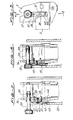
- the portable labeling machine shown in FIGS. 1 to 4 comprises a housing 1 extended by a handle 2 with a control lever 3 articulated on a pivot 4 and connected to a movable print head 5.
- the lever-print head assembly is retained in the rest position as shown in FIG. 1 by a spring 6, partially visible, braced between the handle 2 and the control lever 3.
- the actuation of the lever 3 causes the lowering of the print head 5, according to a trajectory in an arc of a circle signified by the arrow f, and the striking of selected block letters 7 on a self-adhesive label carried by a continuous strip 8 coming from a roll 9 and the circuit of which passes over a fixed printing table 10 integral with the housing 1.
- a step-by-step drive device located under the internal part of the lever 3, is connected to the latter to advance the continuous strip 8, each time this lever is actuated and traditional way, one step ahead corresponding to a length of labels.
- the printing table 10 has a separation edge 11 at which each printed label 12 is separated by its own rigidity from the continuous strip 8, the circuit of which has a hairpin outline at this level, and is placed under a pressure roller 13 intended to allow its bonding by pressure on the object to be labeled.
- the print head 5, shown enlarged and in detail in FIGS. 2, 3 and 4 comprises, sandwiched between two side walls 14 and 15, a plurality of continuous rotary elements carrying printing characters, here constituted by belts 16 in number of 6 held around two spaced series of coaxial wheels 17 of which only the upper series is shown and which are held in elastic support by the tension of these belts in two spaced cylindrical sectors joined by a wall 18 and of which only the upper 19 is shown in section in Figures 3 and 4.
- This print head has a character selection rod 20 with a control button 21, movable around and along its axis of revolution in an elongated bearing 22 carried by the side wall 14.
- This selection rod is coaxial with the series of upper coaxial wheels 17 and comprises an axial latching element 23 as well as rotary drive elements 24 of these wheels, in the traditional manner.
- the two side walls 25 and 26 of the machine housing are also shown in FIGS. 3 and 4, the wall 25 located on the side of the control button 21 having a notch 27, also visible in FIG. 1, intended to allow the free passage of this selection rod during the lowering of the print head causing the typing of the characters.
- the character selection rod 20 is shown in FIG. 3 in the retracted rest position and FIG. 4 in the almost entirely extended position at the end of the selection, this latter position being one of those which cause the problems cited at the start of the presentation and which are inherent to the projection that the rod represents on the side wall 25 of the housing.
- this machine includes a safety device which consists of a retractable movable stop 28 secured to the print head 5, independent of the selection rod 20, and a fixed counter-stop 29, secured to the side wall 26 of the machine housing.
- the retractable movable stop 28 is here constituted by a rocker articulated by its middle part, on a pivot 30 carried by a console 31 projecting from the side wall 15 of the print head.
- This rocker comprises at the end of one of its two arms, here the upper, a stud 32 located substantially in the axis of the selection rod 20 and which is engaged in a hole 33 in the wall 15 opening out to the inside the coaxial wheels 17, opposite the wall 14 located on the side of the control button 21.
- the lower arm 34 of this rocker which constitutes the actual stop, comprises a housing in which is engaged a compression spring 35 braced between this lower arm and the wall 15 in which this spring is also engaged in abutment in a housing.
- the thrust developed by this spring 35 must be less than the retaining force of the latching element 23 of the character selection rod 20.
- the projection of the stud 32 in the hole 33 of the wall 15 must be sufficient for '' at the end of the re-entry travel of the selection rod 20 corresponding in its rest position according to FIG. 3, the end 36 of the latter comes to meet this stud so as to cause the retraction of this movable stop 28 relative to the counter-stop 29, by antagonistic thrust to that of the spring 35.
- the fixed counter-stop 29 is disposed on the active path of the mobile stop 28, that is to say the latter considered in the extended position according to FIG. 4, and substantially at its level in the raised position of rest of the head. printing 5, so that these two members meet at the start of the striking movement of the printing head 5 caused by the actuation of the control lever 3.
- This embodiment of the security device is suitable for labeling machines, the print head of which allows the retractable movable stop to be actuated by the end of the selection rod opposite to the control button 21, that is to say that is to say when a contact element such as the stud 32 can open out opposite said end.
- the retractable movable stop is constituted by a pusher 37 comprising two spaced guide rods 38, parallel to the character selection rod 20, engaged and intended to translate into two bearings of the wall 14 of the head impression 5. This movable stop is located this time on the side of the control button 21 of the selection rod 20.
- This pusher 37 is subjected to the thrust of a spring 40 braced between it and the wall 14 between the two guide rods 38, and takes the form of an arm extended from the rear face of the control button 21, at which level it has a first bearing face 41, up to the upper edge 42 of the side wall 25 of the housing 1 of the machine, at which it has a face forming a stop 43 proper and a second bearing face 44.
- the edge 42 of the housing constitutes the fixed counter-stop.
- the second variant of the safety device shown in Figure 8 avoids the installation of a movable member such as the retractable stop on the print head and can be applied when such an installation presents problems of space.
- This variant is only applicable to machines whose print head allows actuation of the retractable stop by the end of the selection rod opposite to the control button, as in the first example.
- the retractable movable stop is constituted by a cylindrical pusher 45 situated substantially in the axis of the character selection rod 20 in the raised rest position of the print head 5, in a cylindrical housing 46 of the side wall 26 of the machine housing, this pusher comprising a retaining shoulder 47 subjected to the thrust of a spring leaf 48 fixed to said wall, this thrust also being here less than the retaining force of the latching member 23 of the selector rod.
- the active end 49 of this pusher rounded in the shape of a spherical cap, is engaged in a hole 50 in the wall 15 of the print head 5 which opens out opposite the end of the selection rod and opposite its button control 21, when said selector rod is in the extended position as shown in this figure 8.
- This end of the selector rod has a nipple-shaped extension 51 intended to push back the pusher 45 at the end of the rod retracting stroke selection, so as to cause the retraction of this pusher out of the hole 50 by a translation of thrust antagonistic to that of the spring 48.
- this pusher 45 is held in position d 'retraction by a ramp of retaining 52 extending the wall 15 and flush with the orifice of the hole 50 which here acts as a fixed counter-stop, and on which ramp slides the rounded end 49 of this pusher.
- the invention is applicable to portable labeling machines having more than one print head for printing more than one line of characters.
- a retaining device will be associated with each printhead selection rod.
- the lever 28 of the embodiment shown in FIGS. 2, 3 and 4 can be articulated inside the print head 5, on the other face of the wall 15, only its lower end 34 forming abutment being offset to the outside through an opening in this wall.
- This variant can be applied when the selection rod 20 is associated with a parallel index located above it and when this rod cannot open out through an axial hole towards the outside.
- the rocker has a ring-shaped part surrounding the rod of selection so as to allow the upward offset of the stud 32 to place it at the index and have it actuated by the latter.
- the invention is also applicable to labeling machines in which the latching element (23) is not on the character selection rod but on an element integral with this rod, such as for example the index cited above.
Landscapes
- Labeling Devices (AREA)
- Printers Characterized By Their Purpose (AREA)
- Telephone Function (AREA)
- Control Or Security For Electrophotography (AREA)
- Mechanical Pencils And Projecting And Retracting Systems Therefor, And Multi-System Writing Instruments (AREA)
- Catching Or Destruction (AREA)
Priority Applications (1)
| Application Number | Priority Date | Filing Date | Title |
|---|---|---|---|
| AT82105634T ATE10725T1 (de) | 1981-07-17 | 1982-06-25 | Tragbare etikettiermaschine. |
Applications Claiming Priority (2)
| Application Number | Priority Date | Filing Date | Title |
|---|---|---|---|
| CH4695/81 | 1981-07-17 | ||
| CH469581A CH641417A5 (fr) | 1981-07-17 | 1981-07-17 | Machine a etiqueter portative. |
Publications (2)
| Publication Number | Publication Date |
|---|---|
| EP0070418A1 true EP0070418A1 (de) | 1983-01-26 |
| EP0070418B1 EP0070418B1 (de) | 1984-12-12 |
Family
ID=4280896
Family Applications (1)
| Application Number | Title | Priority Date | Filing Date |
|---|---|---|---|
| EP82105634A Expired EP0070418B1 (de) | 1981-07-17 | 1982-06-25 | Tragbare Etikettiermaschine |
Country Status (8)
| Country | Link |
|---|---|
| US (1) | US4450036A (de) |
| EP (1) | EP0070418B1 (de) |
| JP (1) | JPS6058093B2 (de) |
| AT (1) | ATE10725T1 (de) |
| BR (1) | BR8204009A (de) |
| CA (1) | CA1168193A (de) |
| CH (1) | CH641417A5 (de) |
| DE (2) | DE3261541D1 (de) |
Cited By (2)
| Publication number | Priority date | Publication date | Assignee | Title |
|---|---|---|---|---|
| EP0858950A1 (de) * | 1997-02-14 | 1998-08-19 | Duck Hee Lee | Handbetätigtes Etikettiergerät |
| CN111251735A (zh) * | 2020-03-03 | 2020-06-09 | 江苏群杰物联科技有限公司 | 一种法人章(方章)物联网智能盖章装置 |
Families Citing this family (4)
| Publication number | Priority date | Publication date | Assignee | Title |
|---|---|---|---|---|
| DE3406810C2 (de) * | 1984-02-24 | 1986-02-20 | Esselte Pendaflex Corp., Garden City, N.Y. | Handetikettiergerät |
| JPS6410573U (de) * | 1987-07-03 | 1989-01-20 | ||
| US5921180A (en) * | 1997-02-05 | 1999-07-13 | Lee; Duck Hee | Label stamper with tape loading means, guide means, holding means, stamping means, and replaceable cartridge |
| US6428225B1 (en) | 2000-02-18 | 2002-08-06 | Premark Feg L.L.C. | Printer cassette with label stock tensioner arm and associated printer |
Citations (1)
| Publication number | Priority date | Publication date | Assignee | Title |
|---|---|---|---|---|
| US4050375A (en) * | 1976-02-05 | 1977-09-27 | Pitney-Bowes, Inc. | Label printing apparatus |
Family Cites Families (3)
| Publication number | Priority date | Publication date | Assignee | Title |
|---|---|---|---|---|
| JPS5848355B2 (ja) * | 1976-04-10 | 1983-10-27 | 株式会社サト−研究所 | 印刷装置 |
| JPS52125031A (en) * | 1976-04-12 | 1977-10-20 | Sato Co Ltd | Bar code printer |
| JPS5925669Y2 (ja) * | 1979-10-08 | 1984-07-27 | 株式会社サト− | バ−コ−ド用印刷装置 |
-
1981
- 1981-07-17 CH CH469581A patent/CH641417A5/fr not_active IP Right Cessation
-
1982
- 1982-06-03 US US06/384,718 patent/US4450036A/en not_active Expired - Fee Related
- 1982-06-04 CA CA000404470A patent/CA1168193A/en not_active Expired
- 1982-06-16 JP JP57105233A patent/JPS6058093B2/ja not_active Expired
- 1982-06-25 AT AT82105634T patent/ATE10725T1/de not_active IP Right Cessation
- 1982-06-25 DE DE8282105634T patent/DE3261541D1/de not_active Expired
- 1982-06-25 EP EP82105634A patent/EP0070418B1/de not_active Expired
- 1982-06-25 DE DE198282105634T patent/DE70418T1/de active Pending
- 1982-07-09 BR BR8204009A patent/BR8204009A/pt unknown
Patent Citations (1)
| Publication number | Priority date | Publication date | Assignee | Title |
|---|---|---|---|---|
| US4050375A (en) * | 1976-02-05 | 1977-09-27 | Pitney-Bowes, Inc. | Label printing apparatus |
Cited By (2)
| Publication number | Priority date | Publication date | Assignee | Title |
|---|---|---|---|---|
| EP0858950A1 (de) * | 1997-02-14 | 1998-08-19 | Duck Hee Lee | Handbetätigtes Etikettiergerät |
| CN111251735A (zh) * | 2020-03-03 | 2020-06-09 | 江苏群杰物联科技有限公司 | 一种法人章(方章)物联网智能盖章装置 |
Also Published As
| Publication number | Publication date |
|---|---|
| CH641417A5 (fr) | 1984-02-29 |
| JPS5841037A (ja) | 1983-03-10 |
| BR8204009A (pt) | 1983-07-05 |
| EP0070418B1 (de) | 1984-12-12 |
| US4450036A (en) | 1984-05-22 |
| CA1168193A (en) | 1984-05-29 |
| DE3261541D1 (en) | 1985-01-24 |
| DE70418T1 (de) | 1983-05-11 |
| ATE10725T1 (de) | 1984-12-15 |
| JPS6058093B2 (ja) | 1985-12-18 |
Similar Documents
| Publication | Publication Date | Title |
|---|---|---|
| EP2310141B1 (de) | Auftragvorrichtung eines fluids | |
| EP2060507A2 (de) | Verteilerkopf vom Typ Auslösung durch Triggern der Steuerelektrode | |
| FR2727037A1 (fr) | Centrifugeuse a rotor demontable et a dispositif de blocage axial du rotor sur l'arbre d'entrainement | |
| EP2060508A1 (de) | Mit einer Sicherheitsvorrichtung ausgestatteter Behälter | |
| FR2819231A1 (fr) | Unite combinee de changement de vitesse et de commande de frein pour bicyclette | |
| EP0070418B1 (de) | Tragbare Etikettiermaschine | |
| FR2689115A1 (fr) | Tire-bouchon à double appui. | |
| FR2658053A1 (fr) | Applicateur de liquide, par exemple de liquide pour la teinture des cheveux. | |
| EP1199427A1 (de) | Schloss mit verschiebbarem Riegel und verbesserter Sicherheit | |
| EP0798756B1 (de) | Betätigungsmechanismus für elektrischen Schutzschalter mit grossen Öffnungswinkel | |
| EP0367665B1 (de) | Handvorrichtung zur Verstellung eines Sicherheitsgurtels | |
| EP0783971B1 (de) | Abdeckungsvorrichtung für eine Frankiermaschineeinheit | |
| EP0807730B1 (de) | Vorrichtung die den Zugang zu einer bestimmten gesicherten Zone erlaubt | |
| EP0322299B1 (de) | Halterung für ein Reserverad eines Kraftfahrzeuges | |
| WO2018002516A1 (fr) | Poignée came pour mise en place d'un manchon rétractable à froid à l'extrémité d'un câble ou autour d'une jonction entre deux câbles | |
| EP0065172B1 (de) | Tragbare Etikettiermaschine | |
| FR2643276A1 (fr) | Dispositif d'appui, sur un ski, de la partie anterieure de la semelle d'une chaussure | |
| FR2696775A1 (fr) | Perfectionnements aux poignées de porte à palettes basculantes. | |
| EP0369904B1 (de) | Von einem Schnurführungsbügel gesteuerte Angelwinde | |
| EP0058350B1 (de) | Tragbare Etikettiermaschine | |
| FR2857640A1 (fr) | Lave-projecteur telescopique pour vehicule automobile | |
| EP3786395B1 (de) | Zylinderschloss | |
| CA1041044A (fr) | Dispositif de changement de la cartouche d'un stylo | |
| EP0013300B1 (de) | Druckelement mit in einer Kassette angeordneter Typenscheibe | |
| EP0664246A1 (de) | Scheibenwischer für Kraftfahrzeug |
Legal Events
| Date | Code | Title | Description |
|---|---|---|---|
| PUAI | Public reference made under article 153(3) epc to a published international application that has entered the european phase |
Free format text: ORIGINAL CODE: 0009012 |
|
| ITCL | It: translation for ep claims filed |
Representative=s name: STUDIO APRA' |
|
| 17P | Request for examination filed |
Effective date: 19820625 |
|
| AK | Designated contracting states |
Designated state(s): AT BE DE FR GB IT NL SE |
|
| TCAT | At: translation of patent claims filed | ||
| TCNL | Nl: translation of patent claims filed | ||
| DET | De: translation of patent claims | ||
| ITF | It: translation for a ep patent filed | ||
| GRAA | (expected) grant |
Free format text: ORIGINAL CODE: 0009210 |
|
| AK | Designated contracting states |
Designated state(s): AT BE DE FR GB IT NL SE |
|
| REF | Corresponds to: |
Ref document number: 10725 Country of ref document: AT Date of ref document: 19841215 Kind code of ref document: T |
|
| REF | Corresponds to: |
Ref document number: 3261541 Country of ref document: DE Date of ref document: 19850124 |
|
| PLBE | No opposition filed within time limit |
Free format text: ORIGINAL CODE: 0009261 |
|
| STAA | Information on the status of an ep patent application or granted ep patent |
Free format text: STATUS: NO OPPOSITION FILED WITHIN TIME LIMIT |
|
| 26N | No opposition filed | ||
| PGFP | Annual fee paid to national office [announced via postgrant information from national office to epo] |
Ref country code: AT Payment date: 19860613 Year of fee payment: 5 |
|
| PG25 | Lapsed in a contracting state [announced via postgrant information from national office to epo] |
Ref country code: AT Effective date: 19890625 |
|
| PG25 | Lapsed in a contracting state [announced via postgrant information from national office to epo] |
Ref country code: SE Effective date: 19890626 |
|
| PGFP | Annual fee paid to national office [announced via postgrant information from national office to epo] |
Ref country code: DE Payment date: 19910524 Year of fee payment: 10 |
|
| PGFP | Annual fee paid to national office [announced via postgrant information from national office to epo] |
Ref country code: GB Payment date: 19910614 Year of fee payment: 10 |
|
| PGFP | Annual fee paid to national office [announced via postgrant information from national office to epo] |
Ref country code: FR Payment date: 19910619 Year of fee payment: 10 |
|
| ITTA | It: last paid annual fee | ||
| PGFP | Annual fee paid to national office [announced via postgrant information from national office to epo] |
Ref country code: NL Payment date: 19910630 Year of fee payment: 10 |
|
| PGFP | Annual fee paid to national office [announced via postgrant information from national office to epo] |
Ref country code: BE Payment date: 19910806 Year of fee payment: 10 |
|
| PG25 | Lapsed in a contracting state [announced via postgrant information from national office to epo] |
Ref country code: GB Effective date: 19920625 |
|
| PG25 | Lapsed in a contracting state [announced via postgrant information from national office to epo] |
Ref country code: BE Effective date: 19920630 |
|
| BERE | Be: lapsed |
Owner name: ESSELTE PENDAFLEX CORP. Effective date: 19920630 |
|
| PG25 | Lapsed in a contracting state [announced via postgrant information from national office to epo] |
Ref country code: NL Effective date: 19930101 |
|
| NLV4 | Nl: lapsed or anulled due to non-payment of the annual fee | ||
| GBPC | Gb: european patent ceased through non-payment of renewal fee |
Effective date: 19920625 |
|
| PG25 | Lapsed in a contracting state [announced via postgrant information from national office to epo] |
Ref country code: FR Effective date: 19930226 |
|
| PG25 | Lapsed in a contracting state [announced via postgrant information from national office to epo] |
Ref country code: DE Effective date: 19930302 |
|
| REG | Reference to a national code |
Ref country code: FR Ref legal event code: ST |
|
| EUG | Se: european patent has lapsed |
Ref document number: 82105634.8 Effective date: 19900412 |