EP0070607A1 - Absperrbarer Durchbruch durch eine Wand oder einen Fussboden, anwendbar für ein Förderbandsystem - Google Patents
Absperrbarer Durchbruch durch eine Wand oder einen Fussboden, anwendbar für ein Förderbandsystem Download PDFInfo
- Publication number
- EP0070607A1 EP0070607A1 EP82200906A EP82200906A EP0070607A1 EP 0070607 A1 EP0070607 A1 EP 0070607A1 EP 82200906 A EP82200906 A EP 82200906A EP 82200906 A EP82200906 A EP 82200906A EP 0070607 A1 EP0070607 A1 EP 0070607A1
- Authority
- EP
- European Patent Office
- Prior art keywords
- closing panel
- conveyor track
- conveyor
- closable
- framing
- Prior art date
- Legal status (The legal status is an assumption and is not a legal conclusion. Google has not performed a legal analysis and makes no representation as to the accuracy of the status listed.)
- Granted
Links
Images

Classifications
-
- A—HUMAN NECESSITIES
- A62—LIFE-SAVING; FIRE-FIGHTING
- A62C—FIRE-FIGHTING
- A62C2/00—Fire prevention or containment
- A62C2/06—Physical fire-barriers
- A62C2/22—Fire-dampers with provision for the removal of an obstacle, e.g. rails, conveyors, before closing the opening
Definitions
- the invention relates to a closable passage through a wall or a floor, adapted to be passed by a conveyor system, comprising a conveyor track, as well as conveyor elements, such as conveyor receptacles, movable along this conveyor track, wherein the wall or the floor is provided with a passage opening, which is closable by a closing panel, which may be reciprocated between a closed position and a release position, while a conveyor track portion is displaceable between two positions and extends in one of these positions through the passage opening released by the closing panel.
- the closing panel may be reciprocated between the opened or release position and the closed position by means of a drive mechanism.
- the displaceable conveyor track portion can also be moved from the one position to the other, or vice versa, in dependence on the displacement of the closing panel by means of a mechanical transmission mechanism.
- This known closable passage has the disadvantage, that in particular the transmission mechanism, which takes care of the displacement of the conveyor track portion, is rather complicated and sensitive to break-down.
- the closable passage according to the invention is characterized in that the displaceable conveyor track portion is fixedly connected to the closing panel and upon displacement of the closing panel to the release position arrives in its position, wherein this conveyor track portion extends through the passage opening.
- the closing panel may pivot about an axis, which is perpendicular to the direction of the conveyor track.
- end positions of the closing panel may be defined by stops.
- the closing panel may at least partly consist of fire resisting material, while the passage opening is provided with a framing made of fire resisting material, with which the closing panel is in sealing engagement in the closed position.
- a framework composed of sections may be mounted on the wall or the floor and may surround the passage opening, while the framing of fire resisting material is connected to this framework.
- one of the two framing portions extending parallel to the pivot axis of the closing panel, as well as the two framing portions perpendicular to the aforementioned framing portions may form stops for the closing panel in the closed position.
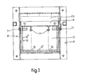
- the drawing shows by way of example an embodiment of a closable passage through a wall 1, which passage is adapted to be passed by a conveyor system.
- This conveyor system consists of a conveyor track 2, which in the embodiment shown by way of example is formed by two rails, along which two conveyor elements, such as conveyor receptacles (not shown) may be moved forward.
- the conveyor elements are suspended from the conveyor track 2, but as an alternative it is also possible that the conveyor elements are supported on the conveyor track 2.
- the wall 1 is provided with a rectangular passage opening 3, which may be closed and released respectively by a closing panel 4, which is also rectangular, for which purpose this closing panel 4 may be pivoted between a closed and a release position.
- first conveyor track stretch 2' and a second conveyor track stretch 2' ' are stationary suspended from a carrier construction 6 by means of clips 5.
- a conveyor track portion 2' ' ' is fixedly connected to the closing panel 4 in order to be able to bridge the distance between the two conveyor track stretches 2', 2'' in the release position of the closing panel 4.
- the closing panel 4 is composed of a plate metal incasement 4' open at one side and a filler 4" of fire resisting material received therein.
- a framework 8 composed of metal angle sections is mounted on the wall 1, which framework surrounds the passage opening 3, a framing 9 of fire resisting material, which is exactly aligned with the passage opening 3 (figs. 2 and 3), being connected thereto.
- the closing panel 4 carries two lugs 10, wherein pivot pins 11 are mounted, which extend through the framing 9 of fire resisting material and which are journalled in the framework 8.
- the pivot axis 7 of the closing panel 4, which is perpendicular to the direction of the conveyor track 1, does not extend along the centre of the closing panel 4, but is displaced to one side thereof. In this way a large free passage is obtained in the release position of the closing panel 4.
- the actuating mechanism (not shown) for the closing panel 4 may engage one of the two pivot pins 11.
- a servo-motor may be used as the actuating mechanism.
- this closing panel 4 may be executed with one or more counter weights, which immediately return the closing panel 4 to the closing position upon switching off of the servo-4 motor.
- a holding magnet, a fuse wire or the like may be applied, which maintains the closing panel 4 in the opened position, while the pivotal movement of the be closing panel 4 may again be carried out by a servo-motor.
- the lower stepped portion 9' of the framing which is parallel to the pivot axis 7 of the closing panel 4, as well as the two upstanding portions 9" of the framing, which are stepped as well, form stops for the closing panel 4 in the 'opened position.
- the lower portion 9' of the framing is provided with passage slots 12 for the conveyor track 2.
- the upper portion 9''' of the framing carries a cap 13, which comprises a filler 14 of fire resisting material joining the upper portion 9' ' ' of the framing of fire resisting material and also functioning as a stop for the closing panel 4 in the closed position of the closing panel 4.
- this closing panel 4 engages a stop 15, which is connected to the carrier construction 6 for the conveyor track 2.
- a closable passage is provided, wherein, upon displacement of the closing panel 4 between the closed position and the release position and vice versa, the conveyor track portion 2"', which is connected to the closing panel 4, is automatically displaced as well. In this way a particular simple construction is obtained.
- closing panel 4 obtains a pivotal movement
- a closing panel 4 which moves in a different way.
- a closable passage through a wall 1 is shown and described in the embodiment given by way of example, of course this passage may also be made through a floor.
Landscapes
- Health & Medical Sciences (AREA)
- Public Health (AREA)
- Business, Economics & Management (AREA)
- Emergency Management (AREA)
- Power-Operated Mechanisms For Wings (AREA)
- Operating, Guiding And Securing Of Roll- Type Closing Members (AREA)
- Special Wing (AREA)
- Specific Sealing Or Ventilating Devices For Doors And Windows (AREA)
- Intermediate Stations On Conveyors (AREA)
- Automobile Manufacture Line, Endless Track Vehicle, Trailer (AREA)
- Structure Of Belt Conveyors (AREA)
Priority Applications (1)
| Application Number | Priority Date | Filing Date | Title |
|---|---|---|---|
| AT82200906T ATE18010T1 (de) | 1981-07-14 | 1982-07-14 | Absperrbarer durchbruch durch eine wand oder einen fussboden, anwendbar fuer ein foerderbandsystem. |
Applications Claiming Priority (2)
| Application Number | Priority Date | Filing Date | Title |
|---|---|---|---|
| NL8103352A NL8103352A (nl) | 1981-07-14 | 1981-07-14 | Afsluitbare doorvoering door een wand of een vloer, bestemd voor het doorlaten van een transportsysteem. |
| NL8103352 | 1981-07-14 |
Publications (2)
| Publication Number | Publication Date |
|---|---|
| EP0070607A1 true EP0070607A1 (de) | 1983-01-26 |
| EP0070607B1 EP0070607B1 (de) | 1986-02-19 |
Family
ID=19837786
Family Applications (1)
| Application Number | Title | Priority Date | Filing Date |
|---|---|---|---|
| EP82200906A Expired EP0070607B1 (de) | 1981-07-14 | 1982-07-14 | Absperrbarer Durchbruch durch eine Wand oder einen Fussboden, anwendbar für ein Förderbandsystem |
Country Status (4)
| Country | Link |
|---|---|
| EP (1) | EP0070607B1 (de) |
| AT (1) | ATE18010T1 (de) |
| DE (1) | DE3269166D1 (de) |
| NL (1) | NL8103352A (de) |
Citations (2)
| Publication number | Priority date | Publication date | Assignee | Title |
|---|---|---|---|---|
| DE2922650A1 (de) * | 1979-06-02 | 1980-12-11 | Ipu Ltd | Feuerabschlussanordnung |
| DE3005234A1 (de) * | 1980-02-13 | 1981-08-20 | I.P.U. Ltd., Nassau | Feuerabschlussvorrichtung |
Family Cites Families (1)
| Publication number | Priority date | Publication date | Assignee | Title |
|---|---|---|---|---|
| DE2547818C2 (de) * | 1975-10-25 | 1984-12-20 | abs-Brandschutz GmbH, 6501 Nieder Olm | Feuerschutzabschluß für eine Öffnung in Wänden oder Decken, welche von einer Förderanlage durchquert wird |
-
1981
- 1981-07-14 NL NL8103352A patent/NL8103352A/nl not_active Application Discontinuation
-
1982
- 1982-07-14 DE DE8282200906T patent/DE3269166D1/de not_active Expired
- 1982-07-14 EP EP82200906A patent/EP0070607B1/de not_active Expired
- 1982-07-14 AT AT82200906T patent/ATE18010T1/de not_active IP Right Cessation
Patent Citations (2)
| Publication number | Priority date | Publication date | Assignee | Title |
|---|---|---|---|---|
| DE2922650A1 (de) * | 1979-06-02 | 1980-12-11 | Ipu Ltd | Feuerabschlussanordnung |
| DE3005234A1 (de) * | 1980-02-13 | 1981-08-20 | I.P.U. Ltd., Nassau | Feuerabschlussvorrichtung |
Also Published As
| Publication number | Publication date |
|---|---|
| ATE18010T1 (de) | 1986-03-15 |
| DE3269166D1 (en) | 1986-03-27 |
| EP0070607B1 (de) | 1986-02-19 |
| NL8103352A (nl) | 1983-02-01 |
Similar Documents
| Publication | Publication Date | Title |
|---|---|---|
| US4249161A (en) | Lock for the doors of automobiles | |
| KR920001591A (ko) | 전기 회로 차단기 조작 블럭 | |
| IE44884L (en) | Doorway | |
| US4773870A (en) | Pull-out frame with a protective plate for a break-contact arrangement | |
| MX166622B (es) | Mejoras en pestillo de cuña de dos piezas, inserto de cierre de barrera de manija e interconexion para la tapa en interruptores de circuito | |
| CA2035706A1 (en) | Snap closing panel holder | |
| EP0070607A1 (de) | Absperrbarer Durchbruch durch eine Wand oder einen Fussboden, anwendbar für ein Förderbandsystem | |
| KR930020510A (ko) | 피벗형제어버튼을 구비한 회로차단기 | |
| US4598264A (en) | Locking mechanism for a mutual mechanical interlocking of two adjoining switch apparatuses | |
| US4176262A (en) | Automatic fail-safe mechanism-operated cell switch for metal-clad switchgear | |
| ES8606818A1 (es) | Cabina de una instalacion de transporte de cable aereo provista de un dispositivo de suspension | |
| KR840005613A (ko) | 밀폐형 전기 제어 패널 | |
| US4134232A (en) | Animal door assembly | |
| US4895271A (en) | Container with closure stay | |
| ATE183806T1 (de) | Tor mit einem bewegbaren torblatt und einer fangklinkeneinrichtung | |
| JPS6070625A (ja) | 電磁開閉器の接点装置 | |
| CA2288702A1 (en) | Mold plate centralizing system | |
| GB2313403A (en) | Stays | |
| JPS6344895Y2 (de) | ||
| DE3162286D1 (en) | Device for opening or closing a door, especially a fire-door | |
| GB2049028A (en) | Panel with counterweight | |
| US1565455A (en) | Switch mechanism | |
| GB2002840A (en) | Sliding door for a lift | |
| KR900003801B1 (ko) | 열릴리스의 열전류 조절방법 및 장치 | |
| JPS5286618A (en) | Door check means for automobiles |
Legal Events
| Date | Code | Title | Description |
|---|---|---|---|
| PUAI | Public reference made under article 153(3) epc to a published international application that has entered the european phase |
Free format text: ORIGINAL CODE: 0009012 |
|
| AK | Designated contracting states |
Designated state(s): AT BE CH DE FR GB IT LI LU NL SE |
|
| 17P | Request for examination filed |
Effective date: 19830721 |
|
| RAP1 | Party data changed (applicant data changed or rights of an application transferred) |
Owner name: ERGON TRANS BV |
|
| GRAA | (expected) grant |
Free format text: ORIGINAL CODE: 0009210 |
|
| AK | Designated contracting states |
Designated state(s): AT BE CH DE FR GB IT LI LU NL SE |
|
| PG25 | Lapsed in a contracting state [announced via postgrant information from national office to epo] |
Ref country code: IT Free format text: LAPSE BECAUSE OF FAILURE TO SUBMIT A TRANSLATION OF THE DESCRIPTION OR TO PAY THE FEE WITHIN THE PRESCRIBED TIME-LIMIT;WARNING: LAPSES OF ITALIAN PATENTS WITH EFFECTIVE DATE BEFORE 2007 MAY HAVE OCCURRED AT ANY TIME BEFORE 2007. THE CORRECT EFFECTIVE DATE MAY BE DIFFERENT FROM THE ONE RECORDED. Effective date: 19860219 Ref country code: FR Free format text: THE PATENT HAS BEEN ANNULLED BY A DECISION OF A NATIONAL AUTHORITY Effective date: 19860219 Ref country code: BE Effective date: 19860219 Ref country code: AT Effective date: 19860219 |
|
| REF | Corresponds to: |
Ref document number: 18010 Country of ref document: AT Date of ref document: 19860315 Kind code of ref document: T |
|
| PG25 | Lapsed in a contracting state [announced via postgrant information from national office to epo] |
Ref country code: SE Effective date: 19860228 |
|
| REF | Corresponds to: |
Ref document number: 3269166 Country of ref document: DE Date of ref document: 19860327 |
|
| EN | Fr: translation not filed | ||
| PG25 | Lapsed in a contracting state [announced via postgrant information from national office to epo] |
Ref country code: LU Free format text: LAPSE BECAUSE OF NON-PAYMENT OF DUE FEES Effective date: 19860731 |
|
| PLBE | No opposition filed within time limit |
Free format text: ORIGINAL CODE: 0009261 |
|
| STAA | Information on the status of an ep patent application or granted ep patent |
Free format text: STATUS: NO OPPOSITION FILED WITHIN TIME LIMIT |
|
| 26N | No opposition filed | ||
| REG | Reference to a national code |
Ref country code: CH Ref legal event code: PFA Free format text: ERGON TRANS B.V. TRANSFER- ERGOTRANS B.V. |
|
| NLT1 | Nl: modifications of names registered in virtue of documents presented to the patent office pursuant to art. 16 a, paragraph 1 |
Owner name: ERGOTRANS B.V. |
|
| PGFP | Annual fee paid to national office [announced via postgrant information from national office to epo] |
Ref country code: CH Payment date: 19980629 Year of fee payment: 17 |
|
| PGFP | Annual fee paid to national office [announced via postgrant information from national office to epo] |
Ref country code: GB Payment date: 19980706 Year of fee payment: 17 |
|
| PG25 | Lapsed in a contracting state [announced via postgrant information from national office to epo] |
Ref country code: GB Free format text: LAPSE BECAUSE OF NON-PAYMENT OF DUE FEES Effective date: 19990714 |
|
| PG25 | Lapsed in a contracting state [announced via postgrant information from national office to epo] |
Ref country code: LI Free format text: LAPSE BECAUSE OF NON-PAYMENT OF DUE FEES Effective date: 19990731 Ref country code: CH Free format text: LAPSE BECAUSE OF NON-PAYMENT OF DUE FEES Effective date: 19990731 |
|
| GBPC | Gb: european patent ceased through non-payment of renewal fee |
Effective date: 19990714 |
|
| REG | Reference to a national code |
Ref country code: CH Ref legal event code: PL |
|
| PGFP | Annual fee paid to national office [announced via postgrant information from national office to epo] |
Ref country code: DE Payment date: 20000703 Year of fee payment: 19 |
|
| PGFP | Annual fee paid to national office [announced via postgrant information from national office to epo] |
Ref country code: NL Payment date: 20000727 Year of fee payment: 19 |
|
| PG25 | Lapsed in a contracting state [announced via postgrant information from national office to epo] |
Ref country code: DE Free format text: LAPSE BECAUSE OF NON-PAYMENT OF DUE FEES Effective date: 20010731 |
|
| PG25 | Lapsed in a contracting state [announced via postgrant information from national office to epo] |
Ref country code: NL Free format text: LAPSE BECAUSE OF NON-PAYMENT OF DUE FEES Effective date: 20020201 |
|
| NLV4 | Nl: lapsed or anulled due to non-payment of the annual fee |
Effective date: 20020201 |