EP0070612B1 - Procédé et dispositif pour diminuer le bond de la bouche de canon d'une arme à feu - Google Patents
Procédé et dispositif pour diminuer le bond de la bouche de canon d'une arme à feu Download PDFInfo
- Publication number
- EP0070612B1 EP0070612B1 EP82302243A EP82302243A EP0070612B1 EP 0070612 B1 EP0070612 B1 EP 0070612B1 EP 82302243 A EP82302243 A EP 82302243A EP 82302243 A EP82302243 A EP 82302243A EP 0070612 B1 EP0070612 B1 EP 0070612B1
- Authority
- EP
- European Patent Office
- Prior art keywords
- muzzle
- compensator
- boss
- weapon
- bore
- Prior art date
- Legal status (The legal status is an assumption and is not a legal conclusion. Google has not performed a legal analysis and makes no representation as to the accuracy of the status listed.)
- Expired
Links
- 239000013598 vector Substances 0.000 claims abstract description 21
- 239000007789 gas Substances 0.000 claims abstract description 13
- 238000010304 firing Methods 0.000 claims abstract description 12
- 230000000694 effects Effects 0.000 claims description 5
- 230000013011 mating Effects 0.000 claims 2
- 230000001629 suppression Effects 0.000 abstract description 10
- 238000010276 construction Methods 0.000 description 2
- 240000005860 Portulaca grandiflora Species 0.000 description 1
- 230000004075 alteration Effects 0.000 description 1
- 230000009194 climbing Effects 0.000 description 1
- 230000001186 cumulative effect Effects 0.000 description 1
- 239000002184 metal Substances 0.000 description 1
- 238000003466 welding Methods 0.000 description 1
Images

Classifications
-
- F—MECHANICAL ENGINEERING; LIGHTING; HEATING; WEAPONS; BLASTING
- F41—WEAPONS
- F41A—FUNCTIONAL FEATURES OR DETAILS COMMON TO BOTH SMALLARMS AND ORDNANCE, e.g. CANNONS; MOUNTINGS FOR SMALLARMS OR ORDNANCE
- F41A21/00—Barrels; Gun tubes; Muzzle attachments; Barrel mounting means
- F41A21/32—Muzzle attachments or glands
- F41A21/36—Muzzle attachments or glands for recoil reduction ; Stabilisators; Compensators, e.g. for muzzle climb prevention
Definitions
- This invention relates to a compensator attaching to the muzzle of a firearm.
- a weapon has a moment arm between the longitudinal axis of the muzzle bore and the effective support of the weapon by the user.
- the reaction force of the projectile of course reacts substantially along the axis of the muzzle bore.
- the support by the user is not on the bore axis, but essentially, is below the axis and to the left in the case of a righthanded person or to the right in the case of a lefthanded person.
- the tendency to swing to the right or to the left is herein termed "swing”.
- the movement of the weapon muzzle upward in the vertical plane is herein termed "climb".
- the word "jump" also would be appropriate but particularly in automatic weapon fire the tendency of the muzzle end to rise is usually termed "climb".
- a muzzle climb compensator which is attached to the muzzle of the weapon and such compensators include a passage through which a projectile or missile may pass.
- the known compensators include symmetrically placed, upwardly, and sometimes rearwardly, extending ports which allow some of the propulsion gases to be emitted upwardly so as to thereby provide a downward force on the muzzle to compensate for climb.
- An example of such a compensator is shown in AT-A-356545.
- Another compensator is shown in US-A-2842024 in which the barrel includes rearward and upwardly directed ports.
- Muzzle brakes are also known which have been designed with a series of ports extending symmetrically around the periphery of a muzzle as disclosed in FR-A-2274886 but the purpose of such a muzzle brake is to reduce recoil.
- the present invention seeks to provide a compensator in which both climb and swing are reduced.
- compensator for attachment to the end of a weapon muzzle for reducing climb and swing momental movement thereof during firing
- said compensator including a body arranged to be detachably connected to the end of a weapon muzzle, said body having a bore which is aligned with the muzzle bore coaxially to permit passage of a projectile or missile therethrough, and wherein the body has upwardly extending ports to allow the exiting of propulsion gases to reduce the climb of the weapon barrel upon firing, characterized in that the body further includes angularly disposed sidewall port means directed radially relative to the centerline of said muzzle bore for producing vector quantities of force extending not only upwardly but laterally of said centerline due to the reaction of propulsion gases exiting through said ports, and adjusting means for variably rotating said body relative to said weapon muzzle whereby said vector force quantities may be angularly adjusted to compensate for both upward climb and lateral swing momental movement.
- the present invention thus provides that by varying the vector angles at which the propulsion gases are emitted from the ports the right amount of compensation for climb or swing for a particular shooter may be achieved.
- the ports are arranged in three longitudinally extending rows, two longer rows arranged so that the two outer rows are of the same length and the center row is arranged to be shorter than the two outside rows.
- the port means preferably have an area of between 0.6 and 1.6 times the cross-sectional area of the bore of said muzzle.
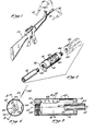
- FIG 1 a weapon 10, such as an M-16 which is capable of automatic fire.
- This invention is particularly useful with an automatic weapon in which the reaction forces of projectiles are cumulative and it is difficult to hold the weapon against climb and swing.
- the end of weapon 10 is shown climbing vertically and swinging right or left, depending on whether the user is righthanded or lefthanded.
- the present compensator is used to oppose these normal tendencies of the weapon to climb or swing by ejecting gas from projectiles through ports 60 directed laterally of the weapon muzzle 12. It will be understood that if during firing the reaction force of projectiles tends to move the end of muzzle 12 upwardly and to the right or left, this tendency can be represented by a vector quantity 50.
- the vector 50 in the case of a righthanded user will be to the right of the vertical.
- the vector 50 will be to the left of the vertical.
- a vector 50 might be at one o'clock in terms of a righthanded user or eleven o'clock in the case of a lefthanded user.
- a user could establish on a firing range what that vector 50 would be and what the clocked position of compensating device 14 would need to be to compensate for the climb and swing tendencies with that user, and weapon ammunition.
- the values could be calibrated approximately for various users and set forth in a table so that with a given weapon and ammunition, the clocked position of the climb and swing vector 50 in terms of degrees, taking vertical upwards as 0°, might be 15° in terms of a righthanded user or 345° in terms of a lefthanded user.
- the opposed vector 54 (the reaction to gases ejecting from ports 60), respectively, would be 195° and 165°.
- Device 14 to reduce climb and swing has a body with a bore therethrough to pass projectiles.
- sound suppression is also incorporated into the device 14, so that it may be constructed with a relatively thin walled cylindrical sleeve 16 and front and rear bored plugs 18 and 20 secured in front and rear ends of sleeve 16, such as by welding.
- device 14 is internally radially enlarged between plugs 18 and 20 thereby achieving a sound suppressing effect.
- rear plug 20 has a concave forward face flaring at about 22° from its center to its edges and forward plug 18 has a rearwardly extending central internal boss 22 about the bore 24 in plug 18, thereby providing an annular space about boss 22 for expansion of gases.
- Both the general central expansion in body 14 and the annular space about boss 22 have sound suppression effects, as will be understood by those skilled in the art, so that air to some extent can pass to the side at the end of muzzle 12 and only exit from device 14 after the projectile has passed.
- the projectile passing before all of the air ahead of it in muzzle 12 also can have an effect on accuracy, as there is less tendency for the projectile to be tumbled by air trying to exit into the atmosphere ahead of the projectile.
- device 14 could be secured on the end of a weapon in various ways.
- device 14 secures onto a threaded boss 30 at the end of the muzzle which is normally used for mounting of flash suppressors, sound suppressors, etc.
- Rear plug 20 has a threaded bore 32 which is of a size to mate with threaded boss 30. It is desirable that once device 14 is adjusted to a particular clocked position, it be locked in position. This could be accomplished in various ways but Figure 3 illustrates a set screw 34 in device 14 which can be tightened against threaded boss 30, once device 14 is in a selected position, in order to hold device 14 against rotation.
- threaded boss 30 on the end of muzzle 12 is provided to mount sound suppressors or flash suppressors.
- a common type of flash suppressor is illustrated at 40 in Figure 2. It has a threaded bore 42 which is of a size to fit on boss 30 on muzzle 12.
- forward plug 18 has a forwardly extending boss 44 with exterior threads of the same size as those on boss 30 of muzzle 12, whereby flash suppressor 40 can be installed on boss 44 with device 14 sandwiched between flash suppressor 40 and muzzle 12.
- Figure 5 illustrates a situation in which more than one device 14 is mounted at the end of muzzle 12, in addition to flash suppressor 40. This assembly might be desirable in a situation where more sound suppression is desired than would be obtained from a single device 14, in which case the plurality of devices 14 in series will further attenuate the sound.
- a vector 50 is illustrated which indicates the normal tendency of the weapon muzzle to climb upwardly and swing to the right when used by a righthanded user.
- vector 50 In order to free firing of the weapon from any tendency to climb or swing due to the moment arm between the users support of the weapon and the longitudinal axis 52 of the weapon muzzle, vector 50 must be opposed by a second vector 54 which is of equal quantity or magnitude and of opposite direction.
- the opposite vectors 50, 54 are illustrated in Figure 4.
- the vector 54 is obtained by reaction force to gases exiting from one or more lateral ports 60 in device 14. If there were only one port 60, of course the vector 54 would extend through the center of the single port.
- ports 60 can be holes or slots of any shape and usually their total will be not less than 60 percent of the area of the bore of the muzzle 12 and no more than one hundred and sixty percent of the area of the weapon muzzle bore. The optimum might be about one hundred and thirty percent of bore area.
- the porting pattern is not critical as long as when the body 14 is rotated right or left, ports 60 function as high speed jets to guide muzzle 12 right or left or up and down so the user can compensate for otherwise undesirable muzzle climb or swing.
- device 14 could be constructed to incorporate a flash suppressor 40 or a like function, but usually it would seem more desirable to provide the device 14 separately from flash suppressor 40 so that either or both could be used and so that existing flash suppressors 40 can be used and will not have to be discarded when used with a weapon having a device 14 for climb and swing suppression.
- tests showed excellent muzzle control, especially in automatic firing modes. Testing also indicated improved accuracy of weapons upon which devices 14 were installed. The tests indicated particularly outstanding accuracy for automatic firing. The tests also indicated, in the configuration shown in Figures 3 and 4, that there was drastic and important reduction in sound pressure level at the muzzle, thereby reducing the sound level to the exposed ear of the user. Further advantages of the use of the device 14 is that the air expansion room in the device leads to greater velocity of the bullet or projectile. The suppression feature reduces recoil of the weapon but that is true of other suppressors. Note that the functions have been provided with no alteration required of the basic weapon 10. If a different ammunition was used significantly more powerful, a different compensator 14 could be used. If porting were provided directly in the weapon barrel 12, as has been done in the prior art, not only would the porting not be adjustable but also sound would be louder, particularly to the user.
- the porting 60 and its functioning can be the same as discussed above.
- the difference in the swing and climb compensating device 114 is that sound suppression is absent. This would be an important feature for particularly the civilian market in which sound suppression would be illegal. There is no appreciable sound suppression in device 114 because there is only a minimal expansion chamber.
- the device as shown may be formed from a single piece of metal with a rear threaded bore 116 fitting on thethreaded boss 30 of the weapon and with a forward boss 118 with external threads of the same size as on muzzle boss 30 so that a device such as a flash suppressor 40 can be installed thereon.
Landscapes
- Engineering & Computer Science (AREA)
- General Engineering & Computer Science (AREA)
- Toys (AREA)
- Aiming, Guidance, Guns With A Light Source, Armor, Camouflage, And Targets (AREA)
- Ladders (AREA)
- Catching Or Destruction (AREA)
- Excavating Of Shafts Or Tunnels (AREA)
Claims (15)
Priority Applications (1)
| Application Number | Priority Date | Filing Date | Title |
|---|---|---|---|
| AT82302243T ATE24759T1 (de) | 1981-05-26 | 1982-04-30 | Verfahren und vorrichtung um den aufsprung des muendungsteiles eines waffenlaufes herabzusetzen. |
Applications Claiming Priority (2)
| Application Number | Priority Date | Filing Date | Title |
|---|---|---|---|
| US26736181A | 1981-05-26 | 1981-05-26 | |
| US267361 | 1981-05-26 |
Publications (3)
| Publication Number | Publication Date |
|---|---|
| EP0070612A2 EP0070612A2 (fr) | 1983-01-26 |
| EP0070612A3 EP0070612A3 (en) | 1983-04-06 |
| EP0070612B1 true EP0070612B1 (fr) | 1987-01-07 |
Family
ID=23018470
Family Applications (1)
| Application Number | Title | Priority Date | Filing Date |
|---|---|---|---|
| EP82302243A Expired EP0070612B1 (fr) | 1981-05-26 | 1982-04-30 | Procédé et dispositif pour diminuer le bond de la bouche de canon d'une arme à feu |
Country Status (3)
| Country | Link |
|---|---|
| EP (1) | EP0070612B1 (fr) |
| AT (1) | ATE24759T1 (fr) |
| DE (1) | DE3275007D1 (fr) |
Families Citing this family (8)
| Publication number | Priority date | Publication date | Assignee | Title |
|---|---|---|---|---|
| US4852460A (en) * | 1988-05-04 | 1989-08-01 | Davidson Windell L | Muzzle brake system |
| GB9106153D0 (en) * | 1991-03-22 | 1991-05-08 | Datestyle Ltd | A muzzle compensator for a gun |
| FR2677743A1 (fr) * | 1991-06-17 | 1992-12-18 | Laporte Jean Michel | Attenuateur de bruit pour fusil de chasse ou de tir sportif. |
| US5753846A (en) * | 1996-11-19 | 1998-05-19 | Sigma Research Inc. | Barrel extender with recoil reduction |
| AT2440U1 (de) * | 1997-08-25 | 1998-10-27 | Andres & Dworsky Uhrenfabrik K | Stabilisator für feuerwaffen |
| US6575266B1 (en) * | 1998-05-29 | 2003-06-10 | Hartmut Gehse | Tube barrel weapon |
| US6604445B2 (en) * | 2001-02-28 | 2003-08-12 | Nicolae Radu Sevastian | Gas trap (GT) compensator |
| US7059235B2 (en) | 2002-09-19 | 2006-06-13 | Hanslick Paul J | Adjustable muzzle stabilizer for repeating firearm |
Citations (1)
| Publication number | Priority date | Publication date | Assignee | Title |
|---|---|---|---|---|
| AT356545B (de) * | 1978-08-02 | 1980-05-12 | Pasaurek Rudolf | Muendungsbremse fuer feuerwaffen, insbesondere fuer gewehre |
Family Cites Families (3)
| Publication number | Priority date | Publication date | Assignee | Title |
|---|---|---|---|---|
| DE356545C (de) * | 1922-07-22 | Albert Scholz | Kaefig fuer Rollenlager | |
| US2842024A (en) * | 1954-12-07 | 1958-07-08 | John F Mutter | Anti-recoil gun barrels |
| FR2274886A1 (fr) * | 1974-06-12 | 1976-01-09 | France Etat | Regulateur de recul pour arme a feu |
-
1982
- 1982-04-30 EP EP82302243A patent/EP0070612B1/fr not_active Expired
- 1982-04-30 AT AT82302243T patent/ATE24759T1/de not_active IP Right Cessation
- 1982-04-30 DE DE8282302243T patent/DE3275007D1/de not_active Expired
Patent Citations (1)
| Publication number | Priority date | Publication date | Assignee | Title |
|---|---|---|---|---|
| AT356545B (de) * | 1978-08-02 | 1980-05-12 | Pasaurek Rudolf | Muendungsbremse fuer feuerwaffen, insbesondere fuer gewehre |
Also Published As
| Publication number | Publication date |
|---|---|
| EP0070612A3 (en) | 1983-04-06 |
| DE3275007D1 (en) | 1987-02-12 |
| ATE24759T1 (de) | 1987-01-15 |
| EP0070612A2 (fr) | 1983-01-26 |
Similar Documents
| Publication | Publication Date | Title |
|---|---|---|
| US6308609B1 (en) | Suppressor | |
| EP3245472B1 (fr) | Accessoire d'arme à feu | |
| US4545285A (en) | Matched expansion muzzle brake | |
| RU2355976C1 (ru) | Надульное устройство ствола огнестрельного оружия | |
| US5631438A (en) | Adjustable gas pressure deflector | |
| US6425310B1 (en) | Muzzle brake | |
| US5063827A (en) | Muzzle blast deflector | |
| US6575074B1 (en) | Omega firearms suppressor | |
| US5794374A (en) | Gun barrel stabilizer | |
| US6302009B1 (en) | Gun noise and recoil suppressor | |
| US10900734B2 (en) | Firearm suppressor | |
| US3776093A (en) | Muzzle blast suppressor | |
| US8061254B2 (en) | Flash suppressor | |
| US5333529A (en) | Convertible muzzle brake | |
| US4664014A (en) | Flash suppressor | |
| US5753846A (en) | Barrel extender with recoil reduction | |
| US2796005A (en) | Rifle control tube | |
| CA1090313A (fr) | Projectile a tete cuneiforme | |
| US4392413A (en) | Muzzle attachment for a firearm barrel | |
| US4852460A (en) | Muzzle brake system | |
| EP0070612B1 (fr) | Procédé et dispositif pour diminuer le bond de la bouche de canon d'une arme à feu | |
| US4635528A (en) | Adjustable firearm stabilizer | |
| US4811648A (en) | Muzzle brake device | |
| US5798474A (en) | Muzzle blast deflector | |
| US5385079A (en) | Vortices-activated muzzle stabilizer for a gun |
Legal Events
| Date | Code | Title | Description |
|---|---|---|---|
| PUAI | Public reference made under article 153(3) epc to a published international application that has entered the european phase |
Free format text: ORIGINAL CODE: 0009012 |
|
| AK | Designated contracting states |
Designated state(s): AT BE CH DE FR GB IT LI SE |
|
| PUAL | Search report despatched |
Free format text: ORIGINAL CODE: 0009013 |
|
| AK | Designated contracting states |
Designated state(s): AT BE CH DE FR GB IT LI SE |
|
| 17P | Request for examination filed |
Effective date: 19831005 |
|
| GRAA | (expected) grant |
Free format text: ORIGINAL CODE: 0009210 |
|
| AK | Designated contracting states |
Kind code of ref document: B1 Designated state(s): AT BE CH DE FR GB IT LI SE |
|
| REF | Corresponds to: |
Ref document number: 24759 Country of ref document: AT Date of ref document: 19870115 Kind code of ref document: T |
|
| ITF | It: translation for a ep patent filed | ||
| REF | Corresponds to: |
Ref document number: 3275007 Country of ref document: DE Date of ref document: 19870212 |
|
| ET | Fr: translation filed | ||
| PLBE | No opposition filed within time limit |
Free format text: ORIGINAL CODE: 0009261 |
|
| STAA | Information on the status of an ep patent application or granted ep patent |
Free format text: STATUS: NO OPPOSITION FILED WITHIN TIME LIMIT |
|
| 26N | No opposition filed | ||
| GBPC | Gb: european patent ceased through non-payment of renewal fee | ||
| PG25 | Lapsed in a contracting state [announced via postgrant information from national office to epo] |
Ref country code: LI Effective date: 19880430 Ref country code: CH Effective date: 19880430 Ref country code: AT Effective date: 19880430 |
|
| PG25 | Lapsed in a contracting state [announced via postgrant information from national office to epo] |
Ref country code: SE Effective date: 19880501 |
|
| BERE | Be: lapsed |
Owner name: FINN CHARLES ALBERT Effective date: 19880430 |
|
| PG25 | Lapsed in a contracting state [announced via postgrant information from national office to epo] |
Ref country code: GB Effective date: 19881121 |
|
| PG25 | Lapsed in a contracting state [announced via postgrant information from national office to epo] |
Ref country code: FR Free format text: LAPSE BECAUSE OF NON-PAYMENT OF DUE FEES Effective date: 19881229 |
|
| REG | Reference to a national code |
Ref country code: CH Ref legal event code: PL |
|
| PG25 | Lapsed in a contracting state [announced via postgrant information from national office to epo] |
Ref country code: DE Effective date: 19890103 |
|
| REG | Reference to a national code |
Ref country code: FR Ref legal event code: ST |
|
| PG25 | Lapsed in a contracting state [announced via postgrant information from national office to epo] |
Ref country code: BE Effective date: 19890430 |
|
| EUG | Se: european patent has lapsed |
Ref document number: 82302243.9 Effective date: 19890510 |