EP0070731A2 - Verfahren zur Zuführung eines feinkörnigen Pulvers - Google Patents
Verfahren zur Zuführung eines feinkörnigen Pulvers Download PDFInfo
- Publication number
- EP0070731A2 EP0070731A2 EP82303796A EP82303796A EP0070731A2 EP 0070731 A2 EP0070731 A2 EP 0070731A2 EP 82303796 A EP82303796 A EP 82303796A EP 82303796 A EP82303796 A EP 82303796A EP 0070731 A2 EP0070731 A2 EP 0070731A2
- Authority
- EP
- European Patent Office
- Prior art keywords
- container
- toner
- fine
- particle powder
- opening
- Prior art date
- Legal status (The legal status is an assumption and is not a legal conclusion. Google has not performed a legal analysis and makes no representation as to the accuracy of the status listed.)
- Withdrawn
Links
- 238000000034 method Methods 0.000 title claims abstract description 28
- 239000000843 powder Substances 0.000 title claims abstract description 15
- 239000010419 fine particle Substances 0.000 title claims abstract description 13
- 238000007639 printing Methods 0.000 claims description 5
- 239000002245 particle Substances 0.000 abstract description 14
- 238000007667 floating Methods 0.000 abstract description 6
- 238000011109 contamination Methods 0.000 abstract description 3
- 238000007789 sealing Methods 0.000 description 5
- 239000000835 fiber Substances 0.000 description 3
- 230000005291 magnetic effect Effects 0.000 description 3
- 239000002184 metal Substances 0.000 description 3
- 229910052751 metal Inorganic materials 0.000 description 3
- XEEYBQQBJWHFJM-UHFFFAOYSA-N Iron Chemical compound [Fe] XEEYBQQBJWHFJM-UHFFFAOYSA-N 0.000 description 2
- VYPSYNLAJGMNEJ-UHFFFAOYSA-N Silicium dioxide Chemical compound O=[Si]=O VYPSYNLAJGMNEJ-UHFFFAOYSA-N 0.000 description 2
- 238000010276 construction Methods 0.000 description 2
- 239000004744 fabric Substances 0.000 description 2
- 230000005294 ferromagnetic effect Effects 0.000 description 2
- 239000006260 foam Substances 0.000 description 2
- 230000005484 gravity Effects 0.000 description 2
- 108091008695 photoreceptors Proteins 0.000 description 2
- 229920002635 polyurethane Polymers 0.000 description 2
- 239000000758 substrate Substances 0.000 description 2
- 239000004952 Polyamide Substances 0.000 description 1
- 239000004698 Polyethylene Substances 0.000 description 1
- 230000002452 interceptive effect Effects 0.000 description 1
- 229910052742 iron Inorganic materials 0.000 description 1
- 239000000463 material Substances 0.000 description 1
- 230000003287 optical effect Effects 0.000 description 1
- 239000000123 paper Substances 0.000 description 1
- 229920002647 polyamide Polymers 0.000 description 1
- -1 polyethylene Polymers 0.000 description 1
- 229920000573 polyethylene Polymers 0.000 description 1
- 239000003566 sealing material Substances 0.000 description 1
- 239000000377 silicon dioxide Substances 0.000 description 1
Images
Classifications
-
- G—PHYSICS
- G03—PHOTOGRAPHY; CINEMATOGRAPHY; ANALOGOUS TECHNIQUES USING WAVES OTHER THAN OPTICAL WAVES; ELECTROGRAPHY; HOLOGRAPHY
- G03G—ELECTROGRAPHY; ELECTROPHOTOGRAPHY; MAGNETOGRAPHY
- G03G15/00—Apparatus for electrographic processes using a charge pattern
- G03G15/06—Apparatus for electrographic processes using a charge pattern for developing
- G03G15/08—Apparatus for electrographic processes using a charge pattern for developing using a solid developer, e.g. powder developer
- G03G15/0822—Arrangements for preparing, mixing, supplying or dispensing developer
- G03G15/0865—Arrangements for supplying new developer
- G03G15/0874—Arrangements for supplying new developer non-rigid containers, e.g. foldable cartridges, bags
-
- G—PHYSICS
- G03—PHOTOGRAPHY; CINEMATOGRAPHY; ANALOGOUS TECHNIQUES USING WAVES OTHER THAN OPTICAL WAVES; ELECTROGRAPHY; HOLOGRAPHY
- G03G—ELECTROGRAPHY; ELECTROPHOTOGRAPHY; MAGNETOGRAPHY
- G03G15/00—Apparatus for electrographic processes using a charge pattern
- G03G15/06—Apparatus for electrographic processes using a charge pattern for developing
- G03G15/08—Apparatus for electrographic processes using a charge pattern for developing using a solid developer, e.g. powder developer
- G03G15/0822—Arrangements for preparing, mixing, supplying or dispensing developer
- G03G15/0848—Arrangements for testing or measuring developer properties or quality, e.g. charge, size, flowability
- G03G15/0849—Detection or control means for the developer concentration
- G03G15/0855—Detection or control means for the developer concentration the concentration being measured by optical means
-
- G—PHYSICS
- G03—PHOTOGRAPHY; CINEMATOGRAPHY; ANALOGOUS TECHNIQUES USING WAVES OTHER THAN OPTICAL WAVES; ELECTROGRAPHY; HOLOGRAPHY
- G03G—ELECTROGRAPHY; ELECTROPHOTOGRAPHY; MAGNETOGRAPHY
- G03G15/00—Apparatus for electrographic processes using a charge pattern
- G03G15/06—Apparatus for electrographic processes using a charge pattern for developing
- G03G15/08—Apparatus for electrographic processes using a charge pattern for developing using a solid developer, e.g. powder developer
- G03G15/0822—Arrangements for preparing, mixing, supplying or dispensing developer
- G03G15/0865—Arrangements for supplying new developer
-
- G—PHYSICS
- G03—PHOTOGRAPHY; CINEMATOGRAPHY; ANALOGOUS TECHNIQUES USING WAVES OTHER THAN OPTICAL WAVES; ELECTROGRAPHY; HOLOGRAPHY
- G03G—ELECTROGRAPHY; ELECTROPHOTOGRAPHY; MAGNETOGRAPHY
- G03G2215/00—Apparatus for electrophotographic processes
- G03G2215/06—Developing structures, details
- G03G2215/066—Toner cartridge or other attachable and detachable container for supplying developer material to replace the used material
- G03G2215/0682—Bag-type non-rigid container
-
- Y—GENERAL TAGGING OF NEW TECHNOLOGICAL DEVELOPMENTS; GENERAL TAGGING OF CROSS-SECTIONAL TECHNOLOGIES SPANNING OVER SEVERAL SECTIONS OF THE IPC; TECHNICAL SUBJECTS COVERED BY FORMER USPC CROSS-REFERENCE ART COLLECTIONS [XRACs] AND DIGESTS
- Y10—TECHNICAL SUBJECTS COVERED BY FORMER USPC
- Y10S—TECHNICAL SUBJECTS COVERED BY FORMER USPC CROSS-REFERENCE ART COLLECTIONS [XRACs] AND DIGESTS
- Y10S222/00—Dispensing
- Y10S222/01—Xerography
Definitions
- the present invention relates to a method of supplying a fine-particle powder from a container to another vessel or a hopper provided in an electrostatic printing apparatus or the like, and particularly a method in which by causing part of said container to engage with part of the apparatus, said container is maintained stationary such that a powder can spontaneously be supplied to said apparatus.
- a method of supplying a fine-particle powder from a container to another vessel or a hopper provided in an electrostatic printing apparatus or the like and particularly a method in which by causing part of said container to engage with part of the apparatus, said container is maintained stationary such that a powder can spontaneously be supplied to said apparatus.
- the closure can be re-mounted on the container.
- the container is left intact in this position until the previously supplied toner in the developing device will have been consumed.
- the first prior art method has a disadvantage in that the toner is scattered or floats in the air on supplying it because of very small specific gravity of the toner which is in the form of fine particles having particle diameters in the range of about 5 ru 30 ⁇ m, resulting in contamination of the surrounding areas and the hands and garment of an operator.
- the second prior art method is an improvement to the first method, but has also a disadvantage in that the operation is very cumbersome because the cartridge must manually be manipulated after it has been set in position.
- the third prior art method is most convenient among them.
- the toner container must always be mounted within the apparatus even if the re-supply of toner is not required. This means that an excess space is required, resulting in the large-sized machine.
- Another object of the present invention is to provide a method for attaining the same purpose as aforementioned, in which an engagement portion formed in an electrostatic printing apparatus adjacent to an opening formed in part of the outside frame thereof is engaged by another engagement portion formed in part of a toner container to maintain the toner container stationary.
- a method of the present invention of supplying a fine-particle powder from a container to an apparatus through an opening therein comprises causing an engagement portion formed in part of said container to co-operate with an engagement portion formed in said apparatus adjacent to said opening such that said fine-particle power can spontaneously be moved while said container is maintained stationary.
- a method of the present invention of supplying powder may comprise causing an engagement portion formed in part of the outer machine frame of an electrostatic printing apparatus to engage with an engagement portion formed in part of a container therein, such that said fine-particle powder can be supplied to a hopper through an opening formed in said apparatus adjacent to said engagement portion thereof.
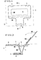
- Figure 1 is a schematic top view of a toner supply section in an apparatus which is one embodiment of the present invention
- Figure 2 is a cross-sectional view taken along a line II-II in Figure 1, showing positional relationship among various components such as cover, hopper and others
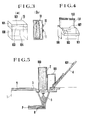
- Figure-3(a) is a schematic view showing the outline of a toner container
- Figure 3(b) is a . schematic view showing the relationship between the toner container and a toner receiving bag
- Figure 4 is a view showing the container in such a state that the lid portion thereof is pivoted and the upper end of the toner receiving bag is cut off
- Figure 5 is a view showing the container in such a state that it is placed on the apparatus of Figure 2 in position.
- Figure 1 is a schematic top view of a supply section to the body of an apparatus
- Figure 2 is a cross-sectional view taken along a line II-II in Figure 1 wherein a cover is shown to be opened.
- reference numeral 1 designates the machine frame of an electrophotographic copying apparatus, 2 the top face thereof, and 3 a T-shaped recess formed in said top face at one end.
- the entire area of the recess is substantially covered by a cover 4 which is pivotably connected to the apparatus by means of two hinges a and b.
- the tip of the cover 4 somewhat extends outwardly from the one end of the apparatus.
- An opening 6 is formed in part of the recess 3 at a position corresponding to a hopper 5 which is mounted within the apparatus.
- the left-hand edge of the opening 6 has a stepped portion 7 formed therein.
- the numer of step in the stepped portion 7 can suitably be selected, for example, to be one or two.
- a stepped portion may not necessarily be provided in the present invention providing a method in which part of the apparatus body co-operates with part of the toner container to simply hold the container stationary, thereby effecting the supply of toner therefrom without any manual operation. Therefore, if only the stepped portion is described with reference to Figure 2 or 5, the left-hand edge of the opening 6 may merely include a flat surface 700 on which the container can be placed at one side edge. Alternatively, the flat surface 700 may be cut out to form a vertical wall 701 which can be used to engage the said wall of the container. Furthermore, a sloped surface may be similarly used in place of the vertical wall 701.
- Reference numeral 8 denotes a toner feeding passage which is provided at the bottom of hopper 5 and includes an apertured feed plate P reciprocable in the passage for carrying the toner from the hopper to a suitable developing device.
- the feed plate 8 is of such dimensions that gaps are formed between the inner walls of the passage and the faces of the feed plate at least at its top and sides (perpendicular to the drawing) so as to smoothly move the feed plate between the inner walls of the passage 8.
- an elastmeric body or sealing member 400 of as polyurethan foam is mounted on that portion of the cover 4 which will engage the perpherical margines of the opening 6 or contact with the flat surface 700.
- This sealing member serves to prevent the floating toner particles from leaking out of the hopper in the normal copying operation.
- the sealing member 400 can be also utilized to be a member for engaging the toner container as well be described hereinafter.
- Reference numeral 401 designates a magnet located on the cover 4 adjacent to the outwardly extending end portion thereof.
- the magnet 401 engages a metal piece 9 disposed on the apparatus in position to lock the cover against the apparatus under the action of magnetic field without any vibration.
- the placement of the above-mentioned magnet and the metal piece may be opposite side.
- Reference numeral 10 designates a box-like container as a whole which comprises a body portion 100 and a lid portion 101.
- the lid portion 101 is adapted to be pivoted about a fold portion 102 which is formed in one face of the container body (sometimes called “back face” or “rearward wall”) at any suitable position.
- the fold portion is perforated to facilitate the movement of the lid portion.
- Reference numeral 103 denotes a tear-off portion which is formed on the front face (sometimes called "forward wall”) of the box-like container.
- the tear-off portion includes one reference side 104 which is actually formed of a perforation and positioned at the same level as that of the fold portion 102 between the top and bottom of the container.
- the tear-off portion also includes the other reference side which is similarly formed of a perforation and spaced away from the first reference side 104 to prevent the other reference side of the tear-off portion from interfering with the top end of a toner receiving container 13 when the lid portion 101 is pivoted.
- the toner receiving container 13 will be described hereinafter and called “toner receiving bag” for avoiding confusion with the toner container 10.
- the side walls of the container and lid 101 are perforated to form stepped portions 105 therein when the tear-off portion 103 is removed.
- Reference numerals 11 and 12 denote fasteners provided on the body portion 100 of the container and the lid portion 101. When the lid portion is pivoted and shifted as shown in Figure 4, these fasteners 11 and 12 engage with each other to hold the container body and lid portions in such a state.
- the fasteners used actually comprise two small pieces 11 and 12 with one of these pieces being constituted of a fabric substrate and a plurality of loop-shaped fiber elements disposed thereon.
- the other small piece is composed of a similar fabric substrate and a plurality of top-hooked fiber elements located thereon which are adapted to engage the loop-shaped fiber elements when the two small pieces are pressed against each other.
- the toner receiving bag 13 is located within the container 10 with the bottom thereof bonded to the bottom and inner face of the container and contains the toner T therein.
- the toner includes hydrohobic silica as one component. When the toner is exposed to air (atmosphere), its flowability is very promoted. The toner particles tend to scatter in air if it is wrongly handled.
- the apparatus has a toner re-supply mechanism of such a construction that includes a hopper and a tonner passage 8 of reduced length as shown in Figures 2 and 5, the toner particles tend to flow out of the passage through the left-hand end thereof on supplying the toner to the hopper.
- Reference numeral 130 designates the heat-sealed end portion.
- Reference numeral 131 denotes so-called "fourchette" portions forming side flaps in the toner receiving bag. The fourchette portions serve to gradually exhaust the toner even if it has its good flowability and ultimately to prevent the scattering or floating of toner particles as far as possible.
- the apparatus body and container thus constructed will be described with the engaging and supplying processes thereof in order.
- a copying apparatus of such a type that includes a movable document platen (not shown) initially positioned above the cover 4 on the top face 2 of the machine frame 1, the platen is first moved to expose the cover area in any suitable manner. Thereafter, the cover 4 is pivoted about the hinges a and b to the position shown in Figure 2 against the magnetic attractive force between the magnet 401 and metal piece 9 by exterting an upward force on the portion of the cover 4 which extends somewhat outwardly from the machine frame. In this pivoted position, the cover 4 is held with an angle by co-operation of said hinges with part of the machine frame as shown in Figure 2. Thus, the toner supply opening 6 and therefore the upper opening of the hopper 5 are exposed.
- the tear-off portion 103 is removed from a new container 10 and the lid portion 101 is pivoted about the fold portion 102.
- the lid and body portions 101, 100 of the container engage with each other at their back faces and are held at this engaged state by means of the fasteners 11 and 12 which engages with each other when these portions 101 and 100 are brought into contact with each other.
- the upper end of the toner receiving bag 13 is exposed and cut off as by scissors to remove the heat-seal portion 130 from the bag. This upper end thus opened is held to provide less opening under the action of the fourchette portion 131 as described hereinbefore.
- the container body opposite to the opened lid portion 101 is then brought into engagement with the flat surface 700 gradually not to cause a relatively large amount of the toner to flow out of the toner receiving bag 10.
- the container will be positioned in its upright position in which the stepped portion of the lid portion 101 is engaged by the sealing member (polyurethan foam) 400 mounted on the inner face of the cover 4.
- the toner container will be maintained stationary by means of the cover 4, vertical wall 701 and flat surface 700. Till this time, the toner gradually falls into the opening 6 spontaneously under the action of gravity. Any scattering and/or floating toner particles are prevented from leaking out of the machine by the container body and lid portions which engage the machine body and cover.
- the amount of scattering and/or floating toner particles is reduced also by the opening of the toner receiving bag 13 which is held at its less opening state under the action of the fourchette portions. After a suitable period of time, the container 10 is removed from the apparatus and then the cover 4 is closed to be ready for copying operation.
- the toner supply method according to the present invention is very simple since the supply of toner can easily be effected without any manual operation by merely positioning the toner container on the apparatus body in position. Therefore, the operator will not feel apprehension about contamination of his hands and garment.
- the container can positively be held and fixed by the engagement of the container with the body of the apparatus.
- the container 10 is made of a thick paper sheet such as cardboard.
- the toner receiving bag is of a double-layer construction made of polyamide sheet and polyethylene sheet which are bonded to each other, in consideration of changes in circumstances, shelf stability and others.
- the toner container and bag may be made of any other suitable material.
- the toner container may be of such a structure that the lid portion 101 is completely cut off from the container body. In such a case, the container may not positively be placed on the apparatus in such a position as shown in the drawings.
- a sloped toner supply passage may be provided between the opening of the hopper 5 and the opening 6 of the machine frame by the use of any suitable sealing material to inert the container which the lid or top thereof is removed into such a sloped passage so that the container can be maintained stationary by engagement of the container with the apparatus.
- the toner supply mechanism for carrying out the method of the present invention may be of course provided within the apparatus.
- the cover 4 is utilized to carry out the method of the present invention in the illustrated embodiment, the cover may not necessarily be used if the object of the present invention can be accomplished without the cover.
Landscapes
- Physics & Mathematics (AREA)
- General Physics & Mathematics (AREA)
- Dry Development In Electrophotography (AREA)
Applications Claiming Priority (2)
| Application Number | Priority Date | Filing Date | Title |
|---|---|---|---|
| JP56115553A JPS5816267A (ja) | 1981-07-22 | 1981-07-22 | 粉体供給方法 |
| JP115553/81 | 1981-07-22 |
Publications (2)
| Publication Number | Publication Date |
|---|---|
| EP0070731A2 true EP0070731A2 (de) | 1983-01-26 |
| EP0070731A3 EP0070731A3 (de) | 1983-06-29 |
Family
ID=14665387
Family Applications (1)
| Application Number | Title | Priority Date | Filing Date |
|---|---|---|---|
| EP82303796A Withdrawn EP0070731A3 (de) | 1981-07-22 | 1982-07-19 | Verfahren zur Zuführung eines feinkörnigen Pulvers |
Country Status (3)
| Country | Link |
|---|---|
| US (1) | US4489765A (de) |
| EP (1) | EP0070731A3 (de) |
| JP (1) | JPS5816267A (de) |
Cited By (2)
| Publication number | Priority date | Publication date | Assignee | Title |
|---|---|---|---|---|
| EP0133901B1 (de) * | 1983-07-18 | 1986-12-17 | International Business Machines Corporation | Tonerauffüllung und Verpackungssystem für Kartuschen |
| EP0627673A3 (de) * | 1993-06-01 | 1996-07-31 | Hewlett Packard Co | Verfahren und Behälter zum Wiedereinfüllen von Toner. |
Families Citing this family (10)
| Publication number | Priority date | Publication date | Assignee | Title |
|---|---|---|---|---|
| DE4013290C1 (de) * | 1990-04-26 | 1991-07-25 | Haver & Boecker, 4740 Oelde, De | |
| US5434655A (en) * | 1994-09-02 | 1995-07-18 | Hewlett-Packard Company | Printer with improved toner loader door |
| JP4157681B2 (ja) * | 2000-02-14 | 2008-10-01 | 株式会社リコー | トナー収納容器 |
| US6484760B1 (en) | 2000-05-11 | 2002-11-26 | Jay Z. Muchin | Container loader ledge |
| JP4299982B2 (ja) * | 2001-06-01 | 2009-07-22 | 株式会社リコー | トナー容器及びこれを用いたトナー補給装置 |
| JP5786210B2 (ja) * | 2010-09-03 | 2015-09-30 | 株式会社タカゾノテクノロジー | ホッパー及びこれを備えた薬剤供給装置 |
| US9494909B1 (en) * | 2015-08-12 | 2016-11-15 | Xerox Corporation | Toner micro-container |
| JP7006094B2 (ja) | 2017-09-28 | 2022-01-24 | ブラザー工業株式会社 | 画像形成装置 |
| KR20190125106A (ko) * | 2018-04-27 | 2019-11-06 | 휴렛-팩커드 디벨롭먼트 컴퍼니, 엘.피. | 장착된 토너 카트리지에 리필 토너 공급 |
| KR20200025336A (ko) * | 2018-08-30 | 2020-03-10 | 휴렛-팩커드 디벨롭먼트 컴퍼니, 엘.피. | 토너 충전부의 유입 셔터를 선택적으로 로킹하는 구조 |
Family Cites Families (9)
| Publication number | Priority date | Publication date | Assignee | Title |
|---|---|---|---|---|
| US2653744A (en) * | 1948-09-01 | 1953-09-29 | Philip W Behr | Feather dispensing unit |
| US3388853A (en) * | 1966-09-19 | 1968-06-18 | Koppers Co Inc | Toner container |
| US3561647A (en) * | 1968-05-01 | 1971-02-09 | Eastman Kodak Co | Apparatus for handling electrographic toner packages |
| US3690544A (en) * | 1971-05-05 | 1972-09-12 | American Can Co | Reducible, reclosable carton |
| US3877499A (en) * | 1973-05-14 | 1975-04-15 | Alfred Fluster | Fluid coupling device |
| US3915208A (en) * | 1973-07-24 | 1975-10-28 | Inforex | Toner supply apparatus with replenishing container |
| US4062385A (en) * | 1975-03-14 | 1977-12-13 | Eastman Kodak Company | Toner handling apparatus |
| FR2428378A7 (fr) * | 1978-04-22 | 1980-01-04 | Agfa Gevaert Ag | Dispositif de developpement pour un appareil de reprographie par voie electrophotographique |
| US4304273A (en) * | 1979-12-31 | 1981-12-08 | International Business Machines Corporation | Toner container and toner dispensing apparatus |
-
1981
- 1981-07-22 JP JP56115553A patent/JPS5816267A/ja active Pending
-
1982
- 1982-07-14 US US06/398,204 patent/US4489765A/en not_active Expired - Lifetime
- 1982-07-19 EP EP82303796A patent/EP0070731A3/de not_active Withdrawn
Cited By (2)
| Publication number | Priority date | Publication date | Assignee | Title |
|---|---|---|---|---|
| EP0133901B1 (de) * | 1983-07-18 | 1986-12-17 | International Business Machines Corporation | Tonerauffüllung und Verpackungssystem für Kartuschen |
| EP0627673A3 (de) * | 1993-06-01 | 1996-07-31 | Hewlett Packard Co | Verfahren und Behälter zum Wiedereinfüllen von Toner. |
Also Published As
| Publication number | Publication date |
|---|---|
| JPS5816267A (ja) | 1983-01-29 |
| EP0070731A3 (de) | 1983-06-29 |
| US4489765A (en) | 1984-12-25 |
Similar Documents
| Publication | Publication Date | Title |
|---|---|---|
| US4523834A (en) | Dry toner replenishing apparatus | |
| EP0070731A2 (de) | Verfahren zur Zuführung eines feinkörnigen Pulvers | |
| EP0992862A3 (de) | Elektrophotographisches Bilderzeugungsgerät, Arbeitseinheit, Entwicklungsvorrichtung, Entwicklerzufuhrbehälter und Messglied dafür | |
| JPH0772725A (ja) | トナー補給装置とそれに使用されるトナーカートリッジ | |
| CA2272984C (en) | Reproduction machine including a developer material cartridge having a non-interfering dual-use sealing device | |
| US4561567A (en) | Toner loading apparatus | |
| EP0470675B1 (de) | Tonerbehälter für Entwicklungsvorrichtung eines latenten elektrostatischen Bildes | |
| US6018637A (en) | Reproduction machine including a developer material cartridge having a label assembly reuseable as a sealing device | |
| EP0106569B1 (de) | Vorrichtung zur Übertragung von teilförmigem Material | |
| JPS63187272A (ja) | 現像器のトナ−補給装置 | |
| GB2103960A (en) | Toner supply device | |
| JPH03267965A (ja) | 現像剤補給装置 | |
| JPS6035062B2 (ja) | 粉体現像剤用カ−トリッジ | |
| JP2006030574A (ja) | トナーカートリッジ及びその脱着機構 | |
| JP2952260B2 (ja) | 容器装置 | |
| JP3354201B2 (ja) | トナー補給装置 | |
| JPH06167882A (ja) | トナー供給装置 | |
| JPS6241324Y2 (de) | ||
| JPS607270B2 (ja) | 現像装置 | |
| JP2921904B2 (ja) | 現像剤容器 | |
| JPH02110584A (ja) | 画像形成装置 | |
| JPS6134566A (ja) | トナ−カ−トリツジ | |
| JPH0256673B2 (de) | ||
| EP1158369A1 (de) | Schnittstelle einer Nachfülleinrichtung | |
| JP3658960B2 (ja) | 粉状体収納容器 |
Legal Events
| Date | Code | Title | Description |
|---|---|---|---|
| PUAI | Public reference made under article 153(3) epc to a published international application that has entered the european phase |
Free format text: ORIGINAL CODE: 0009012 |
|
| AK | Designated contracting states |
Designated state(s): DE FR GB IT NL |
|
| PUAL | Search report despatched |
Free format text: ORIGINAL CODE: 0009013 |
|
| AK | Designated contracting states |
Designated state(s): DE FR GB IT NL |
|
| 17P | Request for examination filed |
Effective date: 19831031 |
|
| STAA | Information on the status of an ep patent application or granted ep patent |
Free format text: STATUS: THE APPLICATION IS DEEMED TO BE WITHDRAWN |
|
| 18D | Application deemed to be withdrawn |
Effective date: 19860429 |
|
| RIN1 | Information on inventor provided before grant (corrected) |
Inventor name: YAMAGUCHI, KEISUKE Inventor name: YAMADA, NOBORU |