EP0070813B1 - Verfahren und Vorrichtung zum Überbringen von Strumpfhosen von einer Nähstelle zu einer Näheinheit zum Anbringen eines Zwickels - Google Patents
Verfahren und Vorrichtung zum Überbringen von Strumpfhosen von einer Nähstelle zu einer Näheinheit zum Anbringen eines Zwickels Download PDFInfo
- Publication number
- EP0070813B1 EP0070813B1 EP82830194A EP82830194A EP0070813B1 EP 0070813 B1 EP0070813 B1 EP 0070813B1 EP 82830194 A EP82830194 A EP 82830194A EP 82830194 A EP82830194 A EP 82830194A EP 0070813 B1 EP0070813 B1 EP 0070813B1
- Authority
- EP
- European Patent Office
- Prior art keywords
- garment
- opening
- machine
- support
- gusset
- Prior art date
- Legal status (The legal status is an assumption and is not a legal conclusion. Google has not performed a legal analysis and makes no representation as to the accuracy of the status listed.)
- Expired
Links
- 238000000034 method Methods 0.000 title claims description 12
- 238000009958 sewing Methods 0.000 title description 21
- 238000000926 separation method Methods 0.000 claims description 5
- 238000004826 seaming Methods 0.000 claims 4
- 208000031968 Cadaver Diseases 0.000 description 4
- 238000006073 displacement reaction Methods 0.000 description 4
- 238000013459 approach Methods 0.000 description 2
- 230000008602 contraction Effects 0.000 description 2
- 230000002093 peripheral effect Effects 0.000 description 2
- 230000015572 biosynthetic process Effects 0.000 description 1
- 210000004027 cell Anatomy 0.000 description 1
- 230000005489 elastic deformation Effects 0.000 description 1
- 239000013013 elastic material Substances 0.000 description 1
- 229940082150 encore Drugs 0.000 description 1
- 239000000463 material Substances 0.000 description 1
- 230000000149 penetrating effect Effects 0.000 description 1
- 230000035515 penetration Effects 0.000 description 1
Images



Classifications
-
- D—TEXTILES; PAPER
- D05—SEWING; EMBROIDERING; TUFTING
- D05B—SEWING
- D05B23/00—Sewing apparatus or machines not otherwise provided for
- D05B23/007—Sewing units for assembling parts of knitted panties or closing the stocking toe part
- D05B23/008—Line closers, i.e. sewing units for forming the body portion of the panty hose
-
- D—TEXTILES; PAPER
- D05—SEWING; EMBROIDERING; TUFTING
- D05D—INDEXING SCHEME ASSOCIATED WITH SUBCLASSES D05B AND D05C, RELATING TO SEWING, EMBROIDERING AND TUFTING
- D05D2207/00—Use of special elements
- D05D2207/02—Pneumatic or hydraulic devices
- D05D2207/04—Suction or blowing devices
-
- D—TEXTILES; PAPER
- D05—SEWING; EMBROIDERING; TUFTING
- D05D—INDEXING SCHEME ASSOCIATED WITH SUBCLASSES D05B AND D05C, RELATING TO SEWING, EMBROIDERING AND TUFTING
- D05D2209/00—Use of special materials
- D05D2209/08—Use of special materials elastic, e.g. rubber spring
-
- D—TEXTILES; PAPER
- D05—SEWING; EMBROIDERING; TUFTING
- D05D—INDEXING SCHEME ASSOCIATED WITH SUBCLASSES D05B AND D05C, RELATING TO SEWING, EMBROIDERING AND TUFTING
- D05D2303/00—Applied objects or articles
- D05D2303/20—Small textile objects e.g., labels, beltloops
Definitions
- the present invention relates to a method and a device for the automatic transfer of tights from a machine for pantyhose with seams to a machine for sewing bellows on tights.
- the present invention has for obtaining the total automation of the operations of removing, transferring and placing the tights, of the machine sewing the tights on that sewing the bellows.
- the invention as characterized in the claims, solves this problem based on a series of operations to be carried out on the garment on which the seams have been previously carried out, anterior and posterior, while leaving the opening sewing center.
- the part (9) is fixed to an axis (10) having in turn a bent shaft (11) fixed to the end of a piston (12) of a cylinder (13); with the displacement of the piston (12) relative to the cylinder (13), the bent shaft (11) describes a circular movement in the direction indicated by the arrow (14) thus causing the rotation of the part (9) in accordance with the Fig. 9 of the attached drawings.
- the part (9) is formed by an outer ring (15) and by another fixed inner ring (16), provided with a number of curved elements (17) having on their free end a rod (19 ) perpendicular to the aforementioned elements and moreover, fixed by rivets (18) themselves fixed to plates (20) provided with buttonholes (21) where in the future the lugs (22) of the movable ring (15) are housed.
- the movable ring (15) is fixed, by a projection (23) of its peripheral part, to the end of a piston (24) placed in a cylinder (25) itself fixed, by the through a tab (26), at the peripheral part of the ring (16).
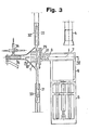
- the ring (15) rotates in the direction indicated by the arrow (27) and, at the same time, the pins (22) rotate in the direction indicated by the arrow (28), which forces the plates (20) with the rivets (18) as well as the rods (19) to rotate in the direction indicated by the arrow (29): consequently, the rods enter the opening ( 12) and cause the widening of its edge as well as the elastic grip of the garment, in accordance with FIG. 3 of the accompanying drawings.
- the ring (16) has, on its inner part, a number of plates (39) of semi-elastic material such as rubber or similar material.
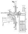
- the device operates as follows: during the first phase, the legs (30-31) of the garment (1) are separated by suction in the pipes (32-33) and the body (35) immobilized on the machine (3) sewing the tights via the presser foot (34); then the carriage (8) is brought closer and the rods (19) are introduced into the opening (2) thus obtaining the elastic grip of the garment (1); then the body (35) is released from the pressure foot (34) and the legs (30-31) are released from the pipes (32-33), which allows the carriage (8) to be moved away, the garment to be removed ( 1) of the machine sewing the tights, as well as retaining it suspended by the rods (19); then the part (9) is rotated, its placement in an aligned position below the support (4) of the machine sewing the bellows; then the part (9) lifts until the ring (16) is around the support (4) and the edge (37) of the garment which will be sewn on the bellows, is placed on the base of said support ( 4) while the support (4) sucks inward the rest of the garment (1);
Landscapes
- Engineering & Computer Science (AREA)
- Textile Engineering (AREA)
- Sewing Machines And Sewing (AREA)
- Treatment Of Fiber Materials (AREA)
Claims (8)
Priority Applications (1)
| Application Number | Priority Date | Filing Date | Title |
|---|---|---|---|
| AT82830194T ATE12408T1 (de) | 1981-07-17 | 1982-06-30 | Verfahren und vorrichtung zum ueberbringen von strumpfhosen von einer naehstelle zu einer naeheinheit zum anbringen eines zwickels. |
Applications Claiming Priority (4)
| Application Number | Priority Date | Filing Date | Title |
|---|---|---|---|
| ES504416A ES504416A0 (es) | 1981-07-17 | 1981-07-17 | Procedimiento para el traslado y posicionado automatico de prendas de vestir desde una maquina cosedora de costuras a una maquina cosedora de refuerzos |
| ES504417A ES504417A0 (es) | 1981-07-17 | 1981-07-17 | Maquina para el traslado y posicionamiento automatico de prendas de vestir desde una maquina cosedora de costuras a una maquina cosedora de refuerzos |
| ES504417 | 1981-07-17 | ||
| ES504416 | 1981-07-17 |
Publications (2)
| Publication Number | Publication Date |
|---|---|
| EP0070813A1 EP0070813A1 (de) | 1983-01-26 |
| EP0070813B1 true EP0070813B1 (de) | 1985-03-27 |
Family
ID=26156018
Family Applications (1)
| Application Number | Title | Priority Date | Filing Date |
|---|---|---|---|
| EP82830194A Expired EP0070813B1 (de) | 1981-07-17 | 1982-06-30 | Verfahren und Vorrichtung zum Überbringen von Strumpfhosen von einer Nähstelle zu einer Näheinheit zum Anbringen eines Zwickels |
Country Status (4)
| Country | Link |
|---|---|
| US (1) | US4485753A (de) |
| EP (1) | EP0070813B1 (de) |
| CA (1) | CA1179303A (de) |
| DE (1) | DE3262781D1 (de) |
Families Citing this family (8)
| Publication number | Priority date | Publication date | Assignee | Title |
|---|---|---|---|---|
| IT1192412B (it) * | 1982-05-03 | 1988-04-13 | Solis Srl | Macchina per cucire tasselli su indumenti a maglia tipo "collant" con alimentazione automatizzata |
| IT1198509B (it) * | 1983-01-21 | 1988-12-21 | Solis Srl | Perfezionamenti relativi ad un procedimento e ad una macchina,per trasferire automaticamente o collants da una macchina che produce collants con cuciture ad una macchina per cucire tasselli |
| IT1212959B (it) * | 1983-08-05 | 1989-12-07 | Solis Srl | Dispositivo per tesare il bordo da cucire al tassello del collant con tassello in macchina cucitasselli con alimentazione automizzata |
| IT1198683B (it) * | 1983-09-19 | 1988-12-21 | Solis Srl | Dispositivo per il caricamento rapido dei collant su macchina di finitura delle calze,specialmente provvista di rovesciatore pneumatico |
| DE3371099D1 (en) * | 1983-09-22 | 1987-05-27 | Solis Srl | Sewing of panty hose on a transfer machine with a plurality of cooperating turrets |
| DE3369862D1 (en) * | 1983-09-22 | 1987-04-02 | Solis Srl | Apparatus for presenting the gore opening of panty hose without wrinkles to a gores sewing machine |
| IT1258180B (it) * | 1992-08-05 | 1996-02-20 | Solis Srl | Metodo per il trasferimento di un collant da una macchina cuci-collants a una macchina cuci-punte e dispositivo per la sua attuazione |
| DE69303716D1 (de) * | 1993-11-18 | 1996-08-22 | Solis Srl | Verfahren und Vorrichtung zum automatischen Beladen einer Nähmaschine zum Anbringen eines Zwickels an gestrickte Kleidungsstücke vom Typ Strumpfhose |
Family Cites Families (4)
| Publication number | Priority date | Publication date | Assignee | Title |
|---|---|---|---|---|
| DE2843169A1 (de) * | 1977-04-04 | 1980-04-17 | Flude & Hinckley | Verfahren und vorrichtung zum einnaehen eines zwickels in ein kleidungsstueck |
| FR2428697A1 (fr) * | 1978-06-13 | 1980-01-11 | Elbetti Meri | Machine a confectionner des collants pourvus d'un soufflet |
| IT1193249B (it) * | 1978-12-12 | 1988-06-15 | Flude & Hinckley | Calze |
| US4364320A (en) * | 1981-02-23 | 1982-12-21 | Consolidated Foods Corporation | Garment toe closing system |
-
1982
- 1982-06-30 EP EP82830194A patent/EP0070813B1/de not_active Expired
- 1982-06-30 DE DE8282830194T patent/DE3262781D1/de not_active Expired
- 1982-07-06 US US06/395,740 patent/US4485753A/en not_active Expired - Fee Related
- 1982-07-16 CA CA000407421A patent/CA1179303A/en not_active Expired
Also Published As
| Publication number | Publication date |
|---|---|
| DE3262781D1 (en) | 1985-05-02 |
| EP0070813A1 (de) | 1983-01-26 |
| CA1179303A (en) | 1984-12-11 |
| US4485753A (en) | 1984-12-04 |
Similar Documents
| Publication | Publication Date | Title |
|---|---|---|
| EP0136391B1 (de) | Nähen von Strumpfhosen auf einer Transfermaschine die aus mehreren, einander folgenden Karussels besteht | |
| JP2580088B2 (ja) | パンティストッキングの自動形成、製造装置及び形成方法 | |
| JP3917639B2 (ja) | 家禽の腹部から内臓物を取り出す内臓物処理装置 | |
| US5419268A (en) | Method and apparatus for assembling garments | |
| CN104937156A (zh) | 用于自动闭合管状产品的轴向端并且用于以内面向外构造卸下管状产品的方法和用于执行该方法的设备 | |
| EP0070813A1 (de) | Verfahren und Vorrichtung zum Überbringen von Strumpfhosen von einer Nähstelle zu einer Näheinheit zum Anbringen eines Zwickels | |
| CN108474150B (zh) | 用于将针织管状物品从里往外翻转的翻转设备 | |
| FR2706796A1 (de) | ||
| US4071924A (en) | Apparatus for removing a fowl from a conveyor | |
| CN114008258B (zh) | 翻转装置、含其的圆形针织机及翻转管状针织物品的方法 | |
| US4622909A (en) | Method and apparatus for applying a gusset to manufactured articles | |
| FR2546380A1 (fr) | Installation pour la fabrication de poignets de chemises | |
| EP0430900A2 (de) | Verfahren und Vorrichtung zum Umwenden von Socken ausserhalb der dazugehörigen Behandlungsmaschine | |
| FR2474816A1 (fr) | Procede et installation pour le demoulage des fromages a pate molle | |
| JP2512466B2 (ja) | ビ―ドをタイヤ組立ドラムに供給する方法及び装置 | |
| EP0306460B1 (de) | Verfahren und Maschine zum automatischen Überführen einer Strumpfhose von einer Zehenschliessenden Nähmaschine zu einer Bügelmaschine | |
| JP2003523895A (ja) | コンパクトディスクを梱包ラインへ移動する方法および装置 | |
| EP0119370B1 (de) | Transfereinrichtung für Strumpfhosen | |
| KR101597164B1 (ko) | 주형 운반용 집게장치 | |
| EP0654554B1 (de) | Verfahren und Vorrichtung zum automatischen Beladen einer Nähmaschine zum Anbringen eines Zwickels an gestrickte Kleidungsstücke vom Typ Strumpfhose | |
| KR101188020B1 (ko) | 양말 편물기용 자동 재봉 장치 | |
| JP3912490B2 (ja) | タイヤ成形機におけるビード自動挿入装置 | |
| JPS62244537A (ja) | 罐巻締方法及びその装置 | |
| JP4213418B2 (ja) | 靴下用型差し装置 | |
| EP0510039A1 (de) | Vorrichtung zum positionieren von strümpfen |
Legal Events
| Date | Code | Title | Description |
|---|---|---|---|
| PUAI | Public reference made under article 153(3) epc to a published international application that has entered the european phase |
Free format text: ORIGINAL CODE: 0009012 |
|
| AK | Designated contracting states |
Designated state(s): AT BE CH DE FR GB IT LI LU NL SE |
|
| ITCL | It: translation for ep claims filed |
Representative=s name: ING. LAZZARO MARTINI |
|
| 17P | Request for examination filed |
Effective date: 19830305 |
|
| ITF | It: translation for a ep patent filed | ||
| GRAA | (expected) grant |
Free format text: ORIGINAL CODE: 0009210 |
|
| AK | Designated contracting states |
Designated state(s): AT BE CH DE FR GB IT LI LU NL SE |
|
| PG25 | Lapsed in a contracting state [announced via postgrant information from national office to epo] |
Ref country code: NL Effective date: 19850327 Ref country code: AT Effective date: 19850327 |
|
| REF | Corresponds to: |
Ref document number: 12408 Country of ref document: AT Date of ref document: 19850415 Kind code of ref document: T |
|
| PG25 | Lapsed in a contracting state [announced via postgrant information from national office to epo] |
Ref country code: SE Effective date: 19850330 |
|
| ITF | It: translation for a ep patent filed | ||
| REF | Corresponds to: |
Ref document number: 3262781 Country of ref document: DE Date of ref document: 19850502 |
|
| PG25 | Lapsed in a contracting state [announced via postgrant information from national office to epo] |
Ref country code: LU Free format text: LAPSE BECAUSE OF NON-PAYMENT OF DUE FEES Effective date: 19850630 Ref country code: LI Effective date: 19850630 Ref country code: CH Effective date: 19850630 Ref country code: BE Effective date: 19850630 |
|
| NLV1 | Nl: lapsed or annulled due to failure to fulfill the requirements of art. 29p and 29m of the patents act | ||
| BERE | Be: lapsed |
Owner name: SOLIS S.R.L. Effective date: 19850630 |
|
| PLBE | No opposition filed within time limit |
Free format text: ORIGINAL CODE: 0009261 |
|
| STAA | Information on the status of an ep patent application or granted ep patent |
Free format text: STATUS: NO OPPOSITION FILED WITHIN TIME LIMIT |
|
| REG | Reference to a national code |
Ref country code: CH Ref legal event code: PL |
|
| 26N | No opposition filed | ||
| ITTA | It: last paid annual fee | ||
| PGFP | Annual fee paid to national office [announced via postgrant information from national office to epo] |
Ref country code: FR Payment date: 19950602 Year of fee payment: 14 |
|
| PGFP | Annual fee paid to national office [announced via postgrant information from national office to epo] |
Ref country code: GB Payment date: 19950609 Year of fee payment: 14 |
|
| PGFP | Annual fee paid to national office [announced via postgrant information from national office to epo] |
Ref country code: DE Payment date: 19950831 Year of fee payment: 14 |
|
| PG25 | Lapsed in a contracting state [announced via postgrant information from national office to epo] |
Ref country code: GB Effective date: 19960630 |
|
| GBPC | Gb: european patent ceased through non-payment of renewal fee |
Effective date: 19960630 |
|
| PG25 | Lapsed in a contracting state [announced via postgrant information from national office to epo] |
Ref country code: FR Effective date: 19970228 |
|
| PG25 | Lapsed in a contracting state [announced via postgrant information from national office to epo] |
Ref country code: DE Effective date: 19970301 |
|
| REG | Reference to a national code |
Ref country code: FR Ref legal event code: ST |