EP0071367B1 - Système autonome d'allocation séquentielle d'un bus de données - Google Patents
Système autonome d'allocation séquentielle d'un bus de données Download PDFInfo
- Publication number
- EP0071367B1 EP0071367B1 EP82303704A EP82303704A EP0071367B1 EP 0071367 B1 EP0071367 B1 EP 0071367B1 EP 82303704 A EP82303704 A EP 82303704A EP 82303704 A EP82303704 A EP 82303704A EP 0071367 B1 EP0071367 B1 EP 0071367B1
- Authority
- EP
- European Patent Office
- Prior art keywords
- data
- line
- supply line
- power
- cable
- Prior art date
- Legal status (The legal status is an assumption and is not a legal conclusion. Google has not performed a legal analysis and makes no representation as to the accuracy of the status listed.)
- Expired
Links
Images

Classifications
-
- H—ELECTRICITY
- H04—ELECTRIC COMMUNICATION TECHNIQUE
- H04Q—SELECTING
- H04Q9/00—Arrangements in telecontrol or telemetry systems for selectively calling a substation from a main station, in which substation desired apparatus is selected for applying a control signal thereto or for obtaining measured values therefrom
Definitions
- the present invention is directed to a simple system for sequentially allocating the use of a data bus to individual members of a series of data communication devices.
- various communication devices such as computer terminals, printers and the like which are capable of transmitting and/or receiving data over a data bus.
- various communications devices for remotely reading such instruments as electrical meters, gas meters, and the like.
- One such device is illustrated and described in United States Patent No. 4,007,454 to Cain et al.
- these devices can be activated or initiated by the receipt of a trigger voltage and can be made to stop drawing current when the data exchange is completed.
- each communication device is equipped with a data bank where data is continuously accumulated and stored in some type of storage member.
- the storage member When the storage member is addressed by a computer, it feeds back the information stored therein. Sequencing of a plurality of such devices is thus accomplished by the computer itself.
- An example of this type of system is shown in United States Patent No. 3,962,545 to Abe and in United States Patent No. 4,059,727 to Kingswell et al. In these systems the data storage and the computer addressing make the systems complicated and expensive, even though the resulting signals may be transmitted over a common telephone line.
- a central computer or addressing device is connected to each data communication device by separate wire leads. Then the central computer or addressing device is pre- set to address each communication device according to a prescribed pattern. This requires an excessive amount of wire and the installation thereof, is very difficult to add instruments once initial wiring is completed, and is relatively slow compared to the present system.
- a polling system includes a plurality of relatively complex transfer members.
- the electrical system includes each device to be read which has alternating conducting and non-conducting areas thereon.
- Each transfer member includes a pair of contacts in engagement with the surface of the device to be read.
- a computer is able to tell the condition (on or off) of each device being scanned. No data is put onto a data bus, bidirectional flow of information cannot take place and each transfer member is activated for a prescribed time interval as preset in the transfer member.
- a relatively simple approach is utilized for sequentially allocating the use of a data bus to individual members of a series of data communication devices.
- the bus used may be parallel (as for communication between microprocessors), or serial (as for example RS-232C as widely used in telephonic data communication) and the data may be analog or serial and may be as complex as desired.
- the receipt of a control signal causes a transfer station to tap a voltage from the supply line, to gate this voltage to its corresponding data communication device so long as current is drawn from the supply line by the data device, and to permit the data device to transmit data onto the bus during the time interval (which may be of arbitrary and/or differing duration) as determined by the device being controlled.
- the present system is directed to the allocation of data transmission opportunity among members of a plurality of data communication devices in accordance with a prescribed sequence. Rather than having the sequencing controlled by a central addressing system, each station on the electrical line activates the next station at the completion of transmission with no appreciable delays.
- a voltage source and a main electrical cable including at least one separate data line.
- the supply line connects the voltage source to a plurality of control means, each of which is electrically connected to a corresponding data communication device by an electrical branch cable having at least a supply line and preferably one data line.
- Each of the control means includes a switch device operable between a normal position and a second position for tapping current from the main cable supply line and gating the current at the same voltage to the supply line of the corresponding branch cable and thus on to the data communication device, thereby activating the same to transmit data onto the branch data line and back onto the main data line or bus.
- the gating of current to a branch line may be so arranged that the supply line current is temporarily withheld from the downstream stations.
- a current sensing means detects the lack of current through the branch cable, returns the switching means to the normal (non-conducting) position, and signals the next-in-line control means to be activated.
- One way, of course, to trigger the entire sequence is to change the voltage on the supply line from zero to a designated high level which will initiate a sequence of readings from the entire line of data communication devices.
- the supply line can substantially be held at a maximum voltage level and the sequence can be triggered when desired with no more than a brief negative pulse on the supply line, whereby the supply line may be used to power other devices when the sequencing is not in progress.
- individual control means may be arranged to respond only to supply voltages above a predetermined threshold, below which voltage level the supply line may be used for other purposes.
- the data commuhication devices are herein assumed to be generally low power devices which can derive all of their operating power from the supply line. This is not a strict requirement, however, as other types of data communication devices might simply sink current or switch current to ground to indicate that they are, or are about to be, putting out data, while deriving their operations power from other sources.
- control devices for future use can be installed during the initial installation or during construction, or they may be installed at any time subsequent to construction or installation of the electrical wiring.
- the system according to the present invention does not require that a central addressing system send out some sort of code over the data lines requesting each control device to respond.
- This "dumb" feature allows the use of simple equipment for requesting and transmitting data, and eliminates the need for a "boss" computer to monitor the system's operation. Moreover, since all data devices may listen to the data bus even while awaiting the opportunity to transmit, communication between devices is enabled without intervention by a central monitoring device.
- the present construction lends itself to additional types of self-sequencing control devices which are responsive to the cessation of power draw by the device controlled. Included for example are such devices as:
- each data communication device is activated in turn to transmit, each can receive data at any time since they are all connected to the common data bus.
- Each data communication device is activated in sequence, transmits data onto a data bus for as long as is necessary, deactivates and causes the system to shift to the next station.
- the sequencing of the system can be initiated by a threshold or trigger voltage, or by such other devices as a computer address or the occurrence of a predetermined event and by monitoring the power drawn by each device, the system is self-sequencing once initiated.
- the system utilizes a power supply line which both provides power to the data communication device being read and produces the self-sequencing results. Power is only supplied to one data communication device at a time, therefore a small amount of power suffices. Should one control station not yet have a data communication device connected thereto or should the communication device draw no current because of a malfunction, the system automatically skips such station because no current is being drawn. As presented herein, a given control means delivers a supply voltage to its data device and continues to do so as long as the device draws current. It will be clear to those skilled in the art that the control means can equally well deliver a supply current to the device so long as a voltage drop associated with the data device indicates to the control means that data are being communicated and the device is still using the bus.
- One of the important features of the invention is that additional data communication devices and/ or control stations therefor may be added to the main circuit after it is initially run merely by cutting the cable and inserting the control station and/or encoder at the appropriate place. Further, the electrical cable may be utilized with the same or other power sources at times when the readings are not being carried out, such as fire alarms, burglar alarms, and the like.
- Another object of the present invention is to provide a self-sequencing data communications network in which the cost and complexity of the equipment required to remote locations and unused time is minimized.
- Yet another object of the present invention is to provide a self-sequencing data acquisition system in which additional stations can easily be added to the existing system with a minimum of effort and at any point so desired.
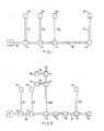
- each of a series of data communicating devices 4a, 4b, 4c, ..., 4n is connected to a corresponding control station 1a, 1b, 1c, ..., 1n by a branch cable 5,-5 " .
- a main electrical cable 3 connects the control stations 1 a, 1 b, 1 c, ..., 1 n, in serial fashion. Initiation of a reading sequence by the impression of a proper voltage and/or current from a power source P onto the cable 3 causes each control station, starting with station 1a, to signal or initiate serial data from its respective data communication device 4a. At the end of its transmission of data, the data communication device 4a will stop drawing current.
- control station 1a This lack of current flow will be immediately sensed at the control station 1a, which then transmits a control signal to the next control station 1 b, thus initiating its data communication device 4b to transmit data onto the cable 3.
- the control station 1b signals the next in-line control station 1c, and so on until all the communication devices have had the opportunity to communicate with the data bus.
- lines a, b, c, and d form the main cable 3.
- a branch cable connects its corresponding data communication device 4 with the main cables.
- the branch cable supply line 5a is connected to the main cable supply line 3a
- the data line or bus 5b is connected to the main cable data bus or line 3b
- the main cable common line 3c is connected to the branch common line 5c.
- the fourth wire 3d of the main cable is utilized in a manner to be described hereinafter.
- the first-in-line control station 1a includes a bi-stable switch 11 (transistor or flip-flop acting as a switch) connected directly to the supply line 3a by means of an auxiliary electrical line 20.
- a bi-stable switch 11 transistor or flip-flop acting as a switch
- This connection between the supply line 3a and the switch component 11 of the control station 1a is the only instance in the entire system that the trigger switch 11 must be connected to the supply line (as in the case of control station 1a by the auxiliary line 20).
- the trigger switch 11 of one station 1 n will be triggered responsive to the cessation of current flow through the previous data communication device 4n-1 as will be explained hereinafter.
- Switch 11 is triggered from its "off” to its "on” position by a prescribed trigger voltage level and/ or current level from the voltage source (for instance 12 volts).
- the corresponding data communication device 4 then feeds data through data line 5b onto the main data bus or line 3b.
- the data communication device 4 stops drawing power through line 5a.
- This cessation of power draw is sensed by the sensing element 10 which detects the power being drawn to be below a prescribed level, at which point the switch 11 is triggered off by a single through line 21 and the next-in-line switch 11 a of the succeeding control station 1b is triggered on.
- the data communication device 4 is selected that operates responsive to the receipt of 9 volts or more.
- the device 4 is of a type which commonly includes or has built therein a silicon controlled rectifier or similar device which determines that the data communication is completed and switches to an alternate state, so that the data communication device 4 no longer draws current.
- This cessation of current flow is detected at each control station 1 by a current sensing technique such as illustrated in element 10, which may be an opto-isolator, Hall effect switch or other similar well-known device.
- element 10 detects that the is of the supply line is below a certain level, the switch 11 is triggered off, and the next switch 11 b of control station 1b is triggered on through the fourth line or the signal line d of the cable 3.
- control station 1a is activated before 1b and control station 1 before 1c c is that control station 1a must pass on a trigger pulse (or a supply voltage in the three wire embodiment referred to hereinbelow) to the next-in-line control station to permit the latter to operate. Therefore the control stations are arranged to operate in their prescribed sequence.
- a failsafe feature it may be necessary or desirable to put in a time-out component (not shown) in the current sensing element so that if a short circuit or device malfunction occurs during the readout and causes the data device to "hang up" while drawing current, after a prescribed time the current sensing element 10 will act as if the current had dropped below the prescribed current level and turn off the corresponding control station, simultaneously turning on the next-in-line control station.
- a timed disconnect feature could be utilized easily and would be within the skill of a person in the art.
- Figure 3 there is illustrated generally the manner in which a system may be set up including branchers 15 which obtain all of the readings from the branch line 22 prior to allowing the current to continue on downstream past the point of brancher 15. Additionally, there may be provided boosters 12 which amplify or reshape the data signals and identifiers 13 which themselves put out data on the data line as if they were data communication devices, yielding, however, no variable reading, merely a pre-set data input consisting of an identifier code. At the end of the entire circuit is shown a terminator 14 in effect a special type of identifier having no pass-through capability which by sending a preset code indicates back along the data bus 3b that the entire sequencing has been completed.
- system described herein can be arranged in a single string of control stations possibly having one or more branches, or alternatively may be arranged in a "ring" or continuous loop which may also have one or more radial branches. In either case, once initiated the sequencing described above will proceed according to the predetermined sequence.
- any data device can selectively address any other device (or all non- selectively if desired) all devices may listen to the bus and take appropriate action responsive to their own individual addresses, but may only transmit to the bus as in reply when the opportunity is provided in sequence by the present invention.
Landscapes
- Engineering & Computer Science (AREA)
- Computer Networks & Wireless Communication (AREA)
- Small-Scale Networks (AREA)
- Traffic Control Systems (AREA)
- Selective Calling Equipment (AREA)
- Electrotherapy Devices (AREA)
- Management, Administration, Business Operations System, And Electronic Commerce (AREA)
Claims (3)
Priority Applications (1)
| Application Number | Priority Date | Filing Date | Title |
|---|---|---|---|
| AT82303704T ATE17979T1 (de) | 1981-07-27 | 1982-07-14 | Datenbuszuweisungssystem mit selbstaendiger folgesteuerung. |
Applications Claiming Priority (2)
| Application Number | Priority Date | Filing Date | Title |
|---|---|---|---|
| US287396 | 1981-07-27 | ||
| US06/287,396 US4438434A (en) | 1981-07-27 | 1981-07-27 | Self-sequencing data bus allocation system |
Publications (3)
| Publication Number | Publication Date |
|---|---|
| EP0071367A2 EP0071367A2 (fr) | 1983-02-09 |
| EP0071367A3 EP0071367A3 (en) | 1983-04-13 |
| EP0071367B1 true EP0071367B1 (fr) | 1986-02-12 |
Family
ID=23102712
Family Applications (1)
| Application Number | Title | Priority Date | Filing Date |
|---|---|---|---|
| EP82303704A Expired EP0071367B1 (fr) | 1981-07-27 | 1982-07-14 | Système autonome d'allocation séquentielle d'un bus de données |
Country Status (9)
| Country | Link |
|---|---|
| US (1) | US4438434A (fr) |
| EP (1) | EP0071367B1 (fr) |
| JP (1) | JPS5827224A (fr) |
| AT (1) | ATE17979T1 (fr) |
| AU (1) | AU550959B2 (fr) |
| BR (1) | BR8204359A (fr) |
| CA (1) | CA1194956A (fr) |
| DE (1) | DE3269062D1 (fr) |
| MX (1) | MX157958A (fr) |
Families Citing this family (15)
| Publication number | Priority date | Publication date | Assignee | Title |
|---|---|---|---|---|
| JPS58107792A (ja) * | 1981-12-22 | 1983-06-27 | Yamatake Honeywell Co Ltd | 空調制御装置におけるデ−タ伝送方式 |
| GB8419641D0 (en) * | 1984-08-01 | 1984-09-05 | Firstquad Ltd | Computer printer scheduler |
| US4833605A (en) * | 1984-08-16 | 1989-05-23 | Mitsubishi Denki Kabushiki Kaisha | Cascaded information processing module having operation unit, parallel port, and serial port for concurrent data transfer and data processing |
| JPS61214702A (ja) * | 1985-03-20 | 1986-09-24 | Mitsubishi Electric Corp | 車両順序選択装置 |
| GB8804340D0 (en) * | 1988-02-24 | 1988-03-23 | Marconi Electronic Devices | Signalling systems |
| JPH0710116B2 (ja) * | 1989-06-14 | 1995-02-01 | 松下電器産業株式会社 | ホームバスシステム及びこのシステムに用いる装置 |
| JPH078071B2 (ja) * | 1990-05-10 | 1995-01-30 | フォッケンフーバー,ペーター | アドレッシング装置 |
| US5450072A (en) * | 1990-05-10 | 1995-09-12 | Vockenhuber; Peter | Addressing device |
| EP0854609A3 (fr) * | 1997-01-21 | 1999-12-22 | Nittan Company, Limited | Système de transmission |
| WO2003094001A1 (fr) * | 2002-05-02 | 2003-11-13 | Elmos Semiconductor Ag | Procede d'adressage de dispositifs utilisateurs d'un systeme a bus au moyen de courants d'identification |
| FR2854627B1 (fr) * | 2003-05-07 | 2006-05-26 | Saint Gobain | Composition de verre silico-sodo-calcique, notamment pour la realisation de substrats |
| CN101219284A (zh) * | 2007-01-08 | 2008-07-16 | 鸿富锦精密工业(深圳)有限公司 | 仿生类装置 |
| DK2927815T3 (en) * | 2008-05-21 | 2017-09-04 | Hewlett Packard Development Co Lp | MULTIDROP SERIAL BUS WITH LOCATION AND PROCEDURE |
| US9454504B2 (en) | 2010-09-30 | 2016-09-27 | Hewlett-Packard Development Company, L.P. | Slave device bit sequence zero driver |
| US8775689B2 (en) | 2011-05-02 | 2014-07-08 | Deere & Company | Electronic modules with automatic configuration |
Family Cites Families (7)
| Publication number | Priority date | Publication date | Assignee | Title |
|---|---|---|---|---|
| US3461445A (en) | 1966-05-09 | 1969-08-12 | Teledyne Exploration Co | Automatic sequencing of data from remote units |
| FR2214385A5 (fr) * | 1973-01-16 | 1974-08-09 | Honeywell Bull Soc Ind | |
| US4148011A (en) | 1977-06-06 | 1979-04-03 | General Automation, Inc. | Asynchronous priority circuit for controlling access to a bus |
| US4245342A (en) | 1979-01-10 | 1981-01-13 | Intech Laboratories, Inc. | One-for-n modem control apparatus |
| US4292623A (en) | 1979-06-29 | 1981-09-29 | International Business Machines Corporation | Port logic for a communication bus system |
| US4313192A (en) | 1979-09-11 | 1982-01-26 | Hydroacoustics, Inc. | Optical transducer array system |
| US4360870A (en) | 1980-07-30 | 1982-11-23 | International Business Machines Corporation | Programmable I/O device identification |
-
1981
- 1981-07-27 US US06/287,396 patent/US4438434A/en not_active Expired - Fee Related
-
1982
- 1982-07-14 DE DE8282303704T patent/DE3269062D1/de not_active Expired
- 1982-07-14 EP EP82303704A patent/EP0071367B1/fr not_active Expired
- 1982-07-14 AT AT82303704T patent/ATE17979T1/de not_active IP Right Cessation
- 1982-07-26 JP JP57130214A patent/JPS5827224A/ja active Pending
- 1982-07-26 BR BR8204359A patent/BR8204359A/pt unknown
- 1982-07-26 MX MX193744A patent/MX157958A/es unknown
- 1982-07-26 AU AU86420/82A patent/AU550959B2/en not_active Ceased
- 1982-07-27 CA CA000408169A patent/CA1194956A/fr not_active Expired
Also Published As
| Publication number | Publication date |
|---|---|
| AU8642082A (en) | 1984-02-02 |
| EP0071367A3 (en) | 1983-04-13 |
| AU550959B2 (en) | 1986-04-10 |
| JPS5827224A (ja) | 1983-02-17 |
| EP0071367A2 (fr) | 1983-02-09 |
| CA1194956A (fr) | 1985-10-08 |
| DE3269062D1 (en) | 1986-03-27 |
| US4438434A (en) | 1984-03-20 |
| BR8204359A (pt) | 1983-07-19 |
| MX157958A (es) | 1988-12-28 |
| ATE17979T1 (de) | 1986-02-15 |
Similar Documents
| Publication | Publication Date | Title |
|---|---|---|
| EP0071367B1 (fr) | Système autonome d'allocation séquentielle d'un bus de données | |
| US3927404A (en) | Time division multiple access communication system for status monitoring | |
| CA1194175A (fr) | Systeme de presentation de donnees autonome insensible aux defaillances | |
| US4097692A (en) | Method and apparatus for the two-way transmission of pulses | |
| US4535401A (en) | Apparatus and method for providing power from master controller to subcontrollers and data communication therebetween | |
| US3891811A (en) | Wire pair identification system | |
| US4476467A (en) | Random entry intercomputer network with collision prevention | |
| US4326289A (en) | Expandable communication system | |
| EP0091290A1 (fr) | Commande d'appareil électrique | |
| EP0201253B1 (fr) | Système de communication dans un réseau de distribution d'énergie | |
| KR830008578A (ko) | 다수의 스테이션(중계국)들을 상호 접속하기 위한 클록와이어와 데이타 와이어를 포함하는 2와이어 버스(Bus) 시스템 | |
| GB2166328A (en) | In-house distribution facility for a broadband communication system | |
| NZ196686A (en) | Remote meter reading control unit | |
| US3728492A (en) | Traffic concentrator for telecommunication system with tree structure | |
| JP2760382B2 (ja) | 制御・監視信号伝送方式 | |
| US4538033A (en) | Data bridge with gating and/or testing | |
| US5583493A (en) | Process and apparatus for the remote polling of measuring points | |
| EP0292226A2 (fr) | Communications d'ordinateurs multiportes et multipoints | |
| AU712697B2 (en) | System for data transmission, remote sensing, remote controls, remote readings and the like, particularly suitable for the electric power distribution lines | |
| WO1982001438A1 (fr) | Unite de supervision par telecommande | |
| US5473308A (en) | Remote supervisory system for network elements | |
| US2796460A (en) | Switching circuit | |
| SU993164A1 (ru) | Устройство дл маркировки многожильного кабел | |
| SU1026148A1 (ru) | Система телемеханики | |
| JPS54116589A (en) | Remote supervisory equipment |
Legal Events
| Date | Code | Title | Description |
|---|---|---|---|
| PUAI | Public reference made under article 153(3) epc to a published international application that has entered the european phase |
Free format text: ORIGINAL CODE: 0009012 |
|
| PUAL | Search report despatched |
Free format text: ORIGINAL CODE: 0009013 |
|
| AK | Designated contracting states |
Designated state(s): AT BE CH DE FR GB IT LI LU NL SE |
|
| AK | Designated contracting states |
Designated state(s): AT BE CH DE FR GB IT LI LU NL SE |
|
| 17P | Request for examination filed |
Effective date: 19830930 |
|
| GRAA | (expected) grant |
Free format text: ORIGINAL CODE: 0009210 |
|
| AK | Designated contracting states |
Designated state(s): AT BE CH DE FR GB IT LI LU NL SE |
|
| PG25 | Lapsed in a contracting state [announced via postgrant information from national office to epo] |
Ref country code: NL Effective date: 19860212 Ref country code: IT Free format text: LAPSE BECAUSE OF FAILURE TO SUBMIT A TRANSLATION OF THE DESCRIPTION OR TO PAY THE FEE WITHIN THE PRESCRIBED TIME-LIMIT;WARNING: LAPSES OF ITALIAN PATENTS WITH EFFECTIVE DATE BEFORE 2007 MAY HAVE OCCURRED AT ANY TIME BEFORE 2007. THE CORRECT EFFECTIVE DATE MAY BE DIFFERENT FROM THE ONE RECORDED. Effective date: 19860212 Ref country code: FR Free format text: THE PATENT HAS BEEN ANNULLED BY A DECISION OF A NATIONAL AUTHORITY Effective date: 19860212 Ref country code: BE Effective date: 19860212 Ref country code: AT Effective date: 19860212 |
|
| REF | Corresponds to: |
Ref document number: 17979 Country of ref document: AT Date of ref document: 19860215 Kind code of ref document: T |
|
| REF | Corresponds to: |
Ref document number: 3269062 Country of ref document: DE Date of ref document: 19860327 |
|
| EN | Fr: translation not filed | ||
| NLV1 | Nl: lapsed or annulled due to failure to fulfill the requirements of art. 29p and 29m of the patents act | ||
| PG25 | Lapsed in a contracting state [announced via postgrant information from national office to epo] |
Ref country code: LU Free format text: LAPSE BECAUSE OF NON-PAYMENT OF DUE FEES Effective date: 19860731 |
|
| PLBE | No opposition filed within time limit |
Free format text: ORIGINAL CODE: 0009261 |
|
| STAA | Information on the status of an ep patent application or granted ep patent |
Free format text: STATUS: NO OPPOSITION FILED WITHIN TIME LIMIT |
|
| 26N | No opposition filed | ||
| PGFP | Annual fee paid to national office [announced via postgrant information from national office to epo] |
Ref country code: SE Payment date: 19890727 Year of fee payment: 8 |
|
| PGFP | Annual fee paid to national office [announced via postgrant information from national office to epo] |
Ref country code: GB Payment date: 19890731 Year of fee payment: 8 |
|
| PGFP | Annual fee paid to national office [announced via postgrant information from national office to epo] |
Ref country code: CH Payment date: 19890804 Year of fee payment: 8 |
|
| PGFP | Annual fee paid to national office [announced via postgrant information from national office to epo] |
Ref country code: DE Payment date: 19890809 Year of fee payment: 8 |
|
| PG25 | Lapsed in a contracting state [announced via postgrant information from national office to epo] |
Ref country code: GB Effective date: 19900714 |
|
| PG25 | Lapsed in a contracting state [announced via postgrant information from national office to epo] |
Ref country code: SE Effective date: 19900715 |
|
| PG25 | Lapsed in a contracting state [announced via postgrant information from national office to epo] |
Ref country code: LI Effective date: 19900731 Ref country code: CH Effective date: 19900731 |
|
| GBPC | Gb: european patent ceased through non-payment of renewal fee | ||
| REG | Reference to a national code |
Ref country code: CH Ref legal event code: PL |
|
| PG25 | Lapsed in a contracting state [announced via postgrant information from national office to epo] |
Ref country code: DE Effective date: 19910403 |
|
| EUG | Se: european patent has lapsed |
Ref document number: 82303704.9 Effective date: 19910402 |