EP0071442A2 - Filtervorrichtung - Google Patents
Filtervorrichtung Download PDFInfo
- Publication number
- EP0071442A2 EP0071442A2 EP82303924A EP82303924A EP0071442A2 EP 0071442 A2 EP0071442 A2 EP 0071442A2 EP 82303924 A EP82303924 A EP 82303924A EP 82303924 A EP82303924 A EP 82303924A EP 0071442 A2 EP0071442 A2 EP 0071442A2
- Authority
- EP
- European Patent Office
- Prior art keywords
- tank
- filtering apparatus
- corrugations
- grid panel
- liquid
- Prior art date
- Legal status (The legal status is an assumption and is not a legal conclusion. Google has not performed a legal analysis and makes no representation as to the accuracy of the status listed.)
- Withdrawn
Links
Images


Classifications
-
- B—PERFORMING OPERATIONS; TRANSPORTING
- B01—PHYSICAL OR CHEMICAL PROCESSES OR APPARATUS IN GENERAL
- B01D—SEPARATION
- B01D29/00—Filters with filtering elements stationary during filtration, e.g. pressure or suction filters, not covered by groups B01D24/00 - B01D27/00; Filtering elements therefor
- B01D29/01—Filters with filtering elements stationary during filtration, e.g. pressure or suction filters, not covered by groups B01D24/00 - B01D27/00; Filtering elements therefor with flat filtering elements
-
- B—PERFORMING OPERATIONS; TRANSPORTING
- B01—PHYSICAL OR CHEMICAL PROCESSES OR APPARATUS IN GENERAL
- B01D—SEPARATION
- B01D29/00—Filters with filtering elements stationary during filtration, e.g. pressure or suction filters, not covered by groups B01D24/00 - B01D27/00; Filtering elements therefor
- B01D29/09—Filters with filtering elements stationary during filtration, e.g. pressure or suction filters, not covered by groups B01D24/00 - B01D27/00; Filtering elements therefor with filtering bands, e.g. movable between filtering operations
-
- B—PERFORMING OPERATIONS; TRANSPORTING
- B01—PHYSICAL OR CHEMICAL PROCESSES OR APPARATUS IN GENERAL
- B01D—SEPARATION
- B01D29/00—Filters with filtering elements stationary during filtration, e.g. pressure or suction filters, not covered by groups B01D24/00 - B01D27/00; Filtering elements therefor
- B01D29/11—Filters with filtering elements stationary during filtration, e.g. pressure or suction filters, not covered by groups B01D24/00 - B01D27/00; Filtering elements therefor with bag, cage, hose, tube, sleeve or like filtering elements
- B01D29/13—Supported filter elements
- B01D29/15—Supported filter elements arranged for inward flow filtration
- B01D29/21—Supported filter elements arranged for inward flow filtration with corrugated, folded or wound sheets
-
- B—PERFORMING OPERATIONS; TRANSPORTING
- B01—PHYSICAL OR CHEMICAL PROCESSES OR APPARATUS IN GENERAL
- B01D—SEPARATION
- B01D29/00—Filters with filtering elements stationary during filtration, e.g. pressure or suction filters, not covered by groups B01D24/00 - B01D27/00; Filtering elements therefor
- B01D29/62—Regenerating the filter material in the filter
- B01D29/64—Regenerating the filter material in the filter by scrapers, brushes, nozzles, or the like, acting on the cake side of the filtering element
- B01D29/6469—Regenerating the filter material in the filter by scrapers, brushes, nozzles, or the like, acting on the cake side of the filtering element scrapers
- B01D29/6484—Regenerating the filter material in the filter by scrapers, brushes, nozzles, or the like, acting on the cake side of the filtering element scrapers with a translatory movement with respect to the filtering element
Definitions
- This invention relates to the art of filtration wherein foreign matter is separated from a liquid flow.
- Liquid filtration wherein foreign matter is separated from a liquid is well known.
- One widely used filter device includes a tank having a pervious bottom which connects with an inclined ramp end wall.
- the tank typically includes a conveyor which comprises a series of transversely positioned flights. Periodically the conveyor is energized so that the flights move across the pervious bottom to remove the foreign material collected thereon. The removed foreign matter is then transported up the ramp by the flights for external disposition.
- the filter media sheet may be either of a permanent or disposable type and interfaces between the conveyor flights and the pervious bottom and inclined ramp.
- Such a liquid filtration device is presently marketed by the applicant hereof under the trademark HYDRO-VAC.
- HYDRO-VAC Such a liquid filtration device is presently marketed by the applicant hereof under the trademark HYDRO-VAC.
- Early examples of this filter type are set forth in U.S. Patent Nos. 3,087,620, 3,091,336 and 3,332,556. Also see U.S. Patent No. 4,250,036 which describes an improved conveyor for use with this type of filter device.
- the filtration apparatus of this invention has several advantages over known filters.
- the corrugated surface of the permeable wall substantially increases the effective area available for liquid flow. Note that while the corrugations are typically vertical, they may also be horizontal. The net result is that the filter may process an increased volume of the foreign material-liquid mixture without being increased in size.
- the corrugations of the wall may be formed to be self-cleaning. Foreign material first retained on upper portions or peaks of the corrugations has a tendency to fall and accumulate in the lower portions or valleys of the corrugations. Thus, a flight conveyor may be operated on a more limited basis. Maintenance costs and energy consumption is thus reduced.
- a secondary benefit of self-cleaning is produced by the foreign material collected in the corrugation valleys.
- the collected foreign material provides further foreign material retention and particularly retention of foreign material having a size sufficiently small to pass through the permeable. wall. Thus foreign material retention efficiency is improved.
- a further advantage is that the configuration of the corrugations can be customized to most efficiently satisfy a particular set of operating parameters.
- the corrugations can be made in a vertical, square tooth, cross sectional configuration. As noted earlier, this area may be further increased by the corrugations having a horizontal as well as a vertically wavy pattern.
- the corrugations may be made in a triangular configuration to promote self-cleaning.
- the corrugations may be made in a vertical sine wave configuration to provide a smoother contact surface between the conveyor flights, the media and the permeable wall. This smoother surface for contact between the flights, the media sheet and the permable wall reduces the possibility of damage to media sheet when flight conveyor is activated.
- the permeable wall is in the form of a permeable grid panel and the apparatus further includes a conveyor operatively carried within the tank with the conveyor having a scraper plate with an edge which complementarily engages the grid panel corrugated surface to remove the foreign material collected thereon.
- the apparatus may conveniently include an inclined ramp carried within the tank and which has a lower end connecting with the grid panel and an upper end interfacing with space external of the tank; the ramp may have an impermeable surface to support the foreign material such that during use the conveyor scraper plate travels over the ramp surface to move the foreign material up the ramp for disposition in the space external of the tank.
- the apparatus may also include a sheet of filter media positioned between the corrugated surface of the grid panel and the conveyor plate; during use the filter media sheet retains the foreign material as the liquid flows through the filter media sheet and grid panel with the sheet being movable relative to the corrugated surface upon activation of the conveying means by the conveyor scraper blade.
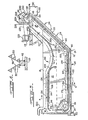
- a filter device of this invention is shown generally and designated 10.
- the filter device 10 includes a holding tank 12 defined by sidewalls 14, 16, a vertical end wall 18, an inclined end wall 20 and a flat bottom 22.
- the inclined end wall 20 extends above the sidewalls 14, 16.
- the bottom 22 and the inclined end wall 20 are reinforced by a series of spaced, laterally positioned channels 24.
- the sidewalls 14, 16 are reinforced by a series of vertical channels 26.
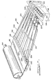
- a permeable grid panel 28 On the bottom 22 is a permeable grid panel 28.
- the panel 28 may be made from a series of spaced, wedge-shaped wires 30, see FIGS. 6 and 9. Alternatively, other perforated materials may be used.
- the wires 30 are longitudinally positioned and formed in a series of vertical, triangular-shaped corrugations 32.
- Each corrugation 32 is defined by an angled sidewall 34.
- Upper ends of adjacent corrugation sidewalls 34 merge at an upper apex and are joined to top round rod 38.
- Lower ends of adjacent corrugation sidewalls 34 merge at a lower apex and are joined respectively to bottom round rods 42.
- each support member 44 Carried longitudinally on the bottom 22 adjacent to each sidewall 14, 16 is a square-shaped support member 44. Projecting inwardly into the tank 12 from each member 44 is a bar 46 which is attached to an inner sidewall 48 of each support member 44. Each outside corrugation 32 of the grid panel 24 has a partial sidewall 50 formed with a horizontal flange 52. The flanges 52 are secured to the support tube bars 46 by bolts 54.
- the vertical cross-sectional configuration of the corrugations 32 can take a number of forms.
- the vertical configuration can be square tooth, triangular, semicircular, and even sine wave.
- the corrugations may be straight as shown in FIG. 1 or shaped in a wavy pattern, for example a sine wave.
- spacing between adjacent wedge wires 30 can be varied depending on relative location on the wedge wires 30 each within the corrugations 32. For example, spaces 56 between the uppermost wedge wires 30 in each corrugation 32 can be decreased in size and the spaces 56 between the lowermost wedge wires 30, as seen in FIG. 6, increased in size. Since a substantial portion of retained foreign matter accumulates in the corrugation valleys, this collected matter also acts to retain further foreign matter.
- Use of varying wedge wire spacing equalizes filtration, i.e. foreign matter retention, across the grid panel 28.
- inner spaces 58 defined by the corrugations 32 and the bottom 22 connect with a discharge header 60.
- the header 60 in turn connects with an outlet fitting 62 carried by the tank vertical end wall 18.
- the header 60 is defined in part by the end wall 18, the bottom 22 and a corner section 64.
- the corner section 64 includes an impervious, radiused, corrugated plate 66.
- the corrugations of the corrugated plate 66 have a similar configuration to the grid panel corrugations 32 so that a lower end of the plate 66 abuts a forward end 68 of the grid panel 28 with the corrugations of the plate 66 and the gird panel 28 aligned.
- An upper end of the corner section 64 is closed by a horizontal plate 70. Attached to the horizontal plate 70 are a series of triangular shaped brackets 72 each having a downwardly inclined guide edge 74. The bracket guide edges 74 align respectively with the top rods 38 of the grid panel 28.
- the ramp section 82 includes flat side portions 84 which align with the inclined end wall 20 and are affixed to the sidewalls 14, 16.
- the corrugations of the ramp 82 are similar in configuration to the grid panel corrugations 32 so that there is alignment between the grid panel 28 and the ramp 82.
- the ramp 82 extends upwardly and terminates at an upper end 86 which is proximately aligned with a top edge 88 of the tank inclined end wall 20.
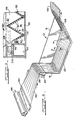
- the filter device 10 further includes a conveyor 90 which is shown in some detail in FIGS. 3, 4 and 5.
- the conveyor 90 includes a pair of spaced chain loops 92, 94.
- the chain loops 92, 94 are carried by four chain sprocket pairs 96, 98, 100, 102.
- Each sprocket pair 96-102 is affixed to a respective shaft 104, 106, 108, 110.
- the shafts 104, 106 and 108 are idle and thus free to rotate.
- Each shaft 104, 106 and 108 has its ends 112 extending through the tank sidewalls 14, 16 and secured in brackets 114 attached to an exterior of the tank sidewalls 14, 16.
- the sprockets 102 are drive sprockets and keyed to the shaft 110 which in turn is a drive shaft.
- the drive shaft 110 is rotatively carried by pillow bearing blocks 116 and is operatively connected to an electric motor 118.
- the electric motor 118 operatively connects with a speed reducer 120 having an output shaft 122.
- Affixed to the output shaft 122 of the speed reducer 120 is a drive sprocket 124.
- the drive sprocket 124 in turn connects to a driven sprocket 126 by a drive chain loop 128.
- the driven sprocket 126 in turn is keyed to the shaft 110.
- the motor 118, speed reducer 120 and drive shaft and sprockets 102, 110 are carried on a raised platform 127 which is attached to the tank sidewalls 14, 16.
- the platform 127 in turn fits over the upper end 86 of the corrugated ramp section 82 and the tank inclined end wall 20.
- the ramp section upper end 86 and the end wall upper end 88 connect with a discharge chute 130 formed with a rectangular opening 132.
- Each flight assembly 134 includes an angle bracket 136. Attached to each end of the bracket 136 is an extension bar 138.
- Each chain loop 92, 94 comprises a series of links 144 alternately joined by a series of side plates 146. Every sixth link 144 has an elongated opening 148 in which the flight assembly extension bars 138 are loosely disposed.
- each flight angle bracket 136 Connected to a vertical leg 156 of each flight angle bracket 136 is a scraper plate 158.
- the scraper plate 158 extends outward from the angle bracket 136 and has a corrugated edge 162 which complementally fits within the corrugations 32 of the grid panel 28, see F IG . 4.
- an upper portion 164 of the chains 92, 94 is supported by chain guides 166, 168. Additionally, the chains 92, 94 are guided in the vertical direction by vertical guides 170 carried by the tank sidewalls 14, 16. The horizontal guides 166, 168 and the vertical guides 170 insure that the chain loops 92, 94 are properly aligned to interact with sprockets 96, 98.
- each chain loop 92, 94 rests on a wear plate 174 carried on a top surface of the support members 44, see FIGS. 4 and 5.
- a bottom surface 176 of a triangular-shaped foreign matter deflection bracket 178 is located immediately above each chain loop lower portion 172.
- a filter media sheet pleating device is shown generally and designated 190.
- the pleating device 190 converts a flat disposable filter media sheet 192 into one having a corrugated or pleated form which may be complementally drawn into the filter 10.
- the sheet 192 is supplied from a roll 194 and moves into an entrance end 196 of the device 190.
- the media sheet 152 could be supplied in a prepleated condition.
- the device 190 comprises an upper guide portion 198 and a lower guide portion 200.
- Each portion 198, 200 has a pair of entrance blocks 202 and exit blocks 204.
- the blocks 202, 204 of each portion 198, 200 are connected by a set of guide wire elements 206, 208 respectively.
- the upper guide wire elements 206 are downwardly sloped between the entrance end 196 and an exit end 210.
- the lower guide wire elements 208 are upwardly sloped so that the sets 206, 208 crisscross in a middle portion of the device 190. As the sheet 192 moves through the device 190, the sheet 192 is transformed to emerge from the device 190 with a pleated configuration.
- the filter media sheet 192 moves over a roller 212 rotatively carried by a platform 214 which may be attached to the end wall 18 of the filter tank 12.
- the roller 212 has a configuration to complementally interact with the sheet 192 and guide the sheet 192 downward to merge with the flight scraper plate 158 and the corner section radiused corrugated guide plate 66.
- the sheet 192 has flat edges 216 to fit under the conveyor chain loops 92, 94, as shown in detail in FIG. 9.
- a flow of liquid containing foreign matter is supplied to the filter tank 12 from an inlet 220 to fill the tank 12 to a level equal to proximately one-half the tank depth.
- the outlet 62 of the tank 12 may be connected to an intake of a pump (not shown) to increase the pressure differential across the grid panel 28 and thus promote the flow of liquid through the grid panel 28.
- the foreign matter is retained by the grid panel 28 where it gradually increases in thickness to form a cake.
- This cake also serves to retain foreign matter so that foreign matter particles of a size which could pass between the spaces 56 between grid panel wedge wires 30 are retained by the cake.
- the filter media sheet 192 is used, the foreign matter is retained by the media 192 and the grid panel 28 functions as a permeable support for the sheet 192. Movement of the filter media sheet 192 is shown schematically in FIG. 8. In FIG. 9 the sheet 192 is shown disposed between the grid panel 28 and flight scraper plate 158.
- the pressure differential across the grid panel 28 also increases indicating a gradual decrease in the flow rate of the liquid through the grid panel 28. Because of the substantial increase in flow area provided by the corrugations 32 of the grid panel 28, the rate of decrease of liquid flow is slowed proportionally.
- the electric motor 118 When the flow rate becomes inefficiently low, the electric motor 118 is energized to activate the conveyor 90.
- the conveyor 90 may operate continuously.
- the chain loops 92, 94 move the flight assemblies 134 in the lower loop portion 172 over the grid panel 28.
- the edges 162 of the scraper plates 158 move over the wedge wire corrugations 32 to remove the foreign matter cake.
- a portion of the grid panel 28 is cleaned.
- the foreign material scraped from the grid panel 28 during previous conveyor activation is pushed up the corrugated ramp section 82 for disposition through the chute 130.
- the flight assemblies 134 move both longitudinally and laterally. In this case the flight assembly bar extensions 138 move in and out of the chain link openings 148 to provide this lateral movement.
- a scraper plate cleaning device 224 is located proximate the pair of drive sprockets 102.
- the device 224 comprises a pair of spaced inverted L-shaped brackets 226 attached at a top of the raised platform 127. Rotatively carried between outer top ends of each bracket 226 is a rod 228. Attached to the rod 228 is a pair of offset shaped straps 230 connected in turn to a horizontal blade 232.
Landscapes
- Chemical & Material Sciences (AREA)
- Chemical Kinetics & Catalysis (AREA)
- Filtration Of Liquid (AREA)
Applications Claiming Priority (2)
| Application Number | Priority Date | Filing Date | Title |
|---|---|---|---|
| US286563 | 1981-07-24 | ||
| US06/286,563 US4389315A (en) | 1981-07-24 | 1981-07-24 | Filter device with permeable corrugated grid panel |
Publications (2)
| Publication Number | Publication Date |
|---|---|
| EP0071442A2 true EP0071442A2 (de) | 1983-02-09 |
| EP0071442A3 EP0071442A3 (de) | 1984-06-13 |
Family
ID=23099170
Family Applications (1)
| Application Number | Title | Priority Date | Filing Date |
|---|---|---|---|
| EP82303924A Withdrawn EP0071442A3 (de) | 1981-07-24 | 1982-07-23 | Filtervorrichtung |
Country Status (2)
| Country | Link |
|---|---|
| US (1) | US4389315A (de) |
| EP (1) | EP0071442A3 (de) |
Cited By (2)
| Publication number | Priority date | Publication date | Assignee | Title |
|---|---|---|---|---|
| GB2160438A (en) * | 1984-06-19 | 1985-12-24 | Coat & Fry Limited | Strainer assembly |
| FR2575397A1 (fr) * | 1984-12-28 | 1986-07-04 | Jackson Philip | Filtre a tablier filtrant mobile ferme en boucle sur lui-meme |
Families Citing this family (19)
| Publication number | Priority date | Publication date | Assignee | Title |
|---|---|---|---|---|
| US4774010A (en) * | 1987-01-05 | 1988-09-27 | Bratten Jack R | Tank filter with conveyor flight driven filter media belt |
| US5024870A (en) * | 1987-02-19 | 1991-06-18 | Donaldson Company, Inc. | Method for potting pleated filter media and filters made thereby |
| US4897206A (en) * | 1988-11-30 | 1990-01-30 | Facet Quantek, Inc. | Bidirectionally corrugated plate separator for fluid mixtures |
| US5165335A (en) * | 1991-09-19 | 1992-11-24 | Stephan Bianchi | Cross-ribbed garlic press |
| US5238584A (en) * | 1992-01-28 | 1993-08-24 | J. R. Schneider Co., Inc. | Apparatus for removing filtrate from filter media |
| US6184510B1 (en) | 1997-11-05 | 2001-02-06 | Rupaco Paper Corporation | Cakeboard and methods of manufacturing and use |
| US5968353A (en) * | 1997-11-14 | 1999-10-19 | Beloit Technologies, Inc. | Clarifier with sludge dewatering |
| DE10027527A1 (de) * | 2000-06-02 | 2001-12-20 | Mega Plast S A | Kunststoffnetz aus Kunststoffstreckfolie sowie Vorrichtung und Verfahren zu seiner Herstellung |
| CN1965019A (zh) * | 2004-05-07 | 2007-05-16 | 株式会社日本触媒 | 一种吸水剂及其制备方法 |
| RU2280618C2 (ru) * | 2004-08-25 | 2006-07-27 | Геннадий Владимирович Шишло | Установка для механической очистки сточных вод |
| WO2008095196A1 (en) | 2007-02-02 | 2008-08-07 | Donaldson Company, Inc. | Air filtration media pack, filter element, air filtration media, and methods |
| US8545589B2 (en) | 2007-06-26 | 2013-10-01 | Donaldson Company, Inc. | Filtration media pack, filter element, and methods |
| MX2010008530A (es) | 2008-02-04 | 2010-08-30 | Donaldson Co Inc | Metodo y aparato para formar uin medio de filtracion acanalado. |
| CN102159296A (zh) * | 2008-07-25 | 2011-08-17 | 唐纳森公司 | 空气过滤介质包装、过滤器元件、空气过滤介质以及方法 |
| JP5711230B2 (ja) | 2009-08-03 | 2015-04-30 | ドナルドソン カンパニー,インコーポレイティド | テーパ付き縦溝流路を有する縦溝流路付き濾過媒体を形成する方法および装置 |
| US9707496B2 (en) * | 2009-09-02 | 2017-07-18 | Terry L. Duperon | Thin plate apparatus for removing debris from water |
| CA2787822A1 (en) | 2010-01-25 | 2011-07-28 | Donaldson Company, Inc. | Pleated filtration media having tapered flutes |
| US11744395B2 (en) | 2021-03-19 | 2023-09-05 | Revise Products Llc | Double-hinged food press device, system and method |
| USD1090200S1 (en) | 2021-03-19 | 2025-08-26 | Revise Products Llc | Garlic press |
Family Cites Families (12)
| Publication number | Priority date | Publication date | Assignee | Title |
|---|---|---|---|---|
| GB743876A (de) * | 1900-01-01 | |||
| US1984891A (en) * | 1931-06-18 | 1934-12-18 | Link Belt Co | Screen |
| US2865509A (en) * | 1955-04-15 | 1958-12-23 | Indiana Commercial Filters Cor | Liquid filtering device |
| US3083831A (en) * | 1959-01-26 | 1963-04-02 | Infilco Inc | Filter for contaminated liquids |
| US3091336A (en) * | 1961-03-27 | 1963-05-28 | Hirs Gene | Filter apparatus |
| US3087620A (en) * | 1961-03-27 | 1963-04-30 | Hirs Gene | Filter apparatus |
| NL301888A (de) * | 1961-12-22 | |||
| GB1085753A (en) * | 1964-10-15 | 1967-10-04 | Gnii Grazhdanskogo Vozdushnogo | Dehydration filter for liquid fuels |
| US3404779A (en) * | 1966-07-26 | 1968-10-08 | Ajem Lab Inc | Filter and sludge conveyor |
| US3385448A (en) * | 1966-12-19 | 1968-05-28 | Monlan Corp | Up-flow self-cleaning filter apparatus |
| US4243527A (en) * | 1979-03-29 | 1981-01-06 | Martin Leonard | Particulate material separator and method |
| US4250036A (en) * | 1979-08-09 | 1981-02-10 | Amsted Industries Incorporated | Conveying means for use in filtering devices |
-
1981
- 1981-07-24 US US06/286,563 patent/US4389315A/en not_active Expired - Fee Related
-
1982
- 1982-07-23 EP EP82303924A patent/EP0071442A3/de not_active Withdrawn
Cited By (3)
| Publication number | Priority date | Publication date | Assignee | Title |
|---|---|---|---|---|
| GB2160438A (en) * | 1984-06-19 | 1985-12-24 | Coat & Fry Limited | Strainer assembly |
| FR2575397A1 (fr) * | 1984-12-28 | 1986-07-04 | Jackson Philip | Filtre a tablier filtrant mobile ferme en boucle sur lui-meme |
| US4692242A (en) * | 1984-12-28 | 1987-09-08 | Philip Jackson | Screen comprising a travelling endless screening band |
Also Published As
| Publication number | Publication date |
|---|---|
| US4389315A (en) | 1983-06-21 |
| EP0071442A3 (de) | 1984-06-13 |
Similar Documents
| Publication | Publication Date | Title |
|---|---|---|
| EP0071442A2 (de) | Filtervorrichtung | |
| EP0760706B1 (de) | Vorrichtung und methode zum filtrieren von flüssigkeit | |
| US6066255A (en) | Belt type filtration apparatus for industrial liquids having multiple sized debris | |
| US4031011A (en) | Magnetic filter apparatus | |
| US4514303A (en) | Sludge traction and desludging system | |
| EP0539467B1 (de) | Entwässerungssystem zum entfernen von schlamm | |
| US6332983B1 (en) | Chip treatment device | |
| US4853116A (en) | Device for collecting and discharging solid matter | |
| CA1123752A (en) | Liquid-solid separator | |
| US4661251A (en) | Filter unit with filter media arrangement for engagement with conveyor flights | |
| EP0024041B1 (de) | Mit Fördervorrichtung für Feststoffe versehene Filtervorrichtung | |
| CA1142451A (en) | Traveling belt filter | |
| US4081375A (en) | Filter belt construction | |
| US3599795A (en) | Apparatus for separating solids from liquids | |
| US3768657A (en) | Sludge tank with self-cleaning screen and screen for use therein | |
| GB2045634A (en) | Screening apparatus | |
| CA1176576A (en) | Filter apparatus | |
| GB2290985A (en) | An Apparatus and method for purifying water | |
| US4842749A (en) | Inversion tube press | |
| EP0244151B1 (de) | Filteranlage | |
| US3757949A (en) | Liquid filter device | |
| CA1124041A (en) | Liquid-solids separator | |
| EP1075865B1 (de) | Vorrichtung zur Verwendung in einer Abwasserbehandlungsanlage | |
| US8136673B2 (en) | Grit elevator | |
| CN213132134U (zh) | 一种污水处理除杂预处理系统 |
Legal Events
| Date | Code | Title | Description |
|---|---|---|---|
| PUAI | Public reference made under article 153(3) epc to a published international application that has entered the european phase |
Free format text: ORIGINAL CODE: 0009012 |
|
| AK | Designated contracting states |
Designated state(s): BE DE FR GB IT |
|
| PUAL | Search report despatched |
Free format text: ORIGINAL CODE: 0009013 |
|
| AK | Designated contracting states |
Designated state(s): BE DE FR GB IT |
|
| STAA | Information on the status of an ep patent application or granted ep patent |
Free format text: STATUS: THE APPLICATION IS DEEMED TO BE WITHDRAWN |
|
| 18D | Application deemed to be withdrawn |
Effective date: 19850201 |
|
| RIN1 | Information on inventor provided before grant (corrected) |
Inventor name: CROKET, FRANK M. |