EP0071496A1 - Gerät zum Zubereiten von Mayonnaisen oder ähnlichen Emulsionen - Google Patents
Gerät zum Zubereiten von Mayonnaisen oder ähnlichen Emulsionen Download PDFInfo
- Publication number
- EP0071496A1 EP0071496A1 EP82401220A EP82401220A EP0071496A1 EP 0071496 A1 EP0071496 A1 EP 0071496A1 EP 82401220 A EP82401220 A EP 82401220A EP 82401220 A EP82401220 A EP 82401220A EP 0071496 A1 EP0071496 A1 EP 0071496A1
- Authority
- EP
- European Patent Office
- Prior art keywords
- oil
- separator
- mixer
- well
- tank
- Prior art date
- Legal status (The legal status is an assumption and is not a legal conclusion. Google has not performed a legal analysis and makes no representation as to the accuracy of the status listed.)
- Granted
Links
- 235000010746 mayonnaise Nutrition 0.000 title claims description 28
- 239000000839 emulsion Substances 0.000 title claims description 7
- 239000008268 mayonnaise Substances 0.000 claims description 24
- 239000004615 ingredient Substances 0.000 claims description 13
- 238000003756 stirring Methods 0.000 claims description 9
- 239000000203 mixture Substances 0.000 claims description 8
- 230000000694 effects Effects 0.000 claims description 5
- 238000005119 centrifugation Methods 0.000 claims description 3
- 238000006243 chemical reaction Methods 0.000 claims 1
- 230000008878 coupling Effects 0.000 description 4
- 238000010168 coupling process Methods 0.000 description 4
- 238000005859 coupling reaction Methods 0.000 description 4
- 241000219198 Brassica Species 0.000 description 3
- 235000003351 Brassica cretica Nutrition 0.000 description 3
- 235000003343 Brassica rupestris Nutrition 0.000 description 3
- 102000002322 Egg Proteins Human genes 0.000 description 3
- 108010000912 Egg Proteins Proteins 0.000 description 3
- QKSKPIVNLNLAAV-UHFFFAOYSA-N bis(2-chloroethyl) sulfide Chemical compound ClCCSCCCl QKSKPIVNLNLAAV-UHFFFAOYSA-N 0.000 description 3
- 235000013345 egg yolk Nutrition 0.000 description 3
- 210000002969 egg yolk Anatomy 0.000 description 3
- 235000010460 mustard Nutrition 0.000 description 3
- 238000002360 preparation method Methods 0.000 description 3
- 238000007789 sealing Methods 0.000 description 3
- 230000002349 favourable effect Effects 0.000 description 2
- 230000005484 gravity Effects 0.000 description 2
- 238000004519 manufacturing process Methods 0.000 description 2
- 235000013599 spices Nutrition 0.000 description 2
- 239000012258 stirred mixture Substances 0.000 description 2
- 235000021419 vinegar Nutrition 0.000 description 2
- 239000000052 vinegar Substances 0.000 description 2
- 240000002234 Allium sativum Species 0.000 description 1
- 241000219193 Brassicaceae Species 0.000 description 1
- 235000002566 Capsicum Nutrition 0.000 description 1
- 239000006002 Pepper Substances 0.000 description 1
- 235000016761 Piper aduncum Nutrition 0.000 description 1
- 235000017804 Piper guineense Nutrition 0.000 description 1
- 244000203593 Piper nigrum Species 0.000 description 1
- 235000008184 Piper nigrum Nutrition 0.000 description 1
- 240000008042 Zea mays Species 0.000 description 1
- 238000010521 absorption reaction Methods 0.000 description 1
- 230000015572 biosynthetic process Effects 0.000 description 1
- 230000003247 decreasing effect Effects 0.000 description 1
- 235000013305 food Nutrition 0.000 description 1
- 235000004611 garlic Nutrition 0.000 description 1
- 238000012986 modification Methods 0.000 description 1
- 230000004048 modification Effects 0.000 description 1
- 230000000284 resting effect Effects 0.000 description 1
- 150000003839 salts Chemical class 0.000 description 1
- 238000000926 separation method Methods 0.000 description 1
- 235000002639 sodium chloride Nutrition 0.000 description 1
Images
Classifications
-
- B—PERFORMING OPERATIONS; TRANSPORTING
- B01—PHYSICAL OR CHEMICAL PROCESSES OR APPARATUS IN GENERAL
- B01F—MIXING, e.g. DISSOLVING, EMULSIFYING OR DISPERSING
- B01F27/00—Mixers with rotary stirring devices in fixed receptacles; Kneaders
- B01F27/80—Mixers with rotary stirring devices in fixed receptacles; Kneaders with stirrers rotating about a substantially vertical axis
-
- A—HUMAN NECESSITIES
- A47—FURNITURE; DOMESTIC ARTICLES OR APPLIANCES; COFFEE MILLS; SPICE MILLS; SUCTION CLEANERS IN GENERAL
- A47J—KITCHEN EQUIPMENT; COFFEE MILLS; SPICE MILLS; APPARATUS FOR MAKING BEVERAGES
- A47J43/00—Implements for preparing or holding food, not provided for in other groups of this subclass
- A47J43/04—Machines for domestic use not covered elsewhere, e.g. for grinding, mixing, stirring, kneading, emulsifying, whipping or beating foodstuffs, e.g. power-driven
- A47J43/044—Machines for domestic use not covered elsewhere, e.g. for grinding, mixing, stirring, kneading, emulsifying, whipping or beating foodstuffs, e.g. power-driven with tools driven from the top side
Definitions
- the present invention relates to a household appliance for making mayonnaise or similar food emulsions.
- the aforementioned emulsions can be prepared using a manual or mechanical whisk intended to beat and stir the ingredients.
- French patent 1,089,420 has proposed an apparatus comprising a brewing chamber surmounted by an oil reservoir connected to the brewing chamber by a calibrated communication.
- the oil flows if not evenly, at least slowly in the brewing chamber and is incorporated into the mixture as it flows.
- Such a device certainly reduces the risk of failure in the preparation of mayonnaise.
- it has the drawback of being bulky, the stirring chamber and the oil tank necessarily having both an appreciable volume.
- the object of the present invention is to remedy this drawback by producing a household appliance which is particularly space-saving and makes it possible to make mayonnaises without any particular skill.
- the invention thus relates to a household appliance for making mayonnaises or similar emulsions, which comprises a stirring chamber in which is mounted a rotary mechanical mixer, an oil tank, a calibrated communication between the oil tank and the brewing chamber, and means for during brewing, passing the oil from the tank to the brewing chamber by the calibrated communication.
- this apparatus is characterized in that the reservoir and the chamber are arranged in an apparatus body on either side of a sliding separator.
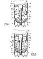
- the separator is in an extreme position in which the brewing chamber is as small as possible while the oil tank is as large as possible.
- the mechanical mixer is started, which begins by mixing the aforementioned ingredients contained in the brewing chamber.
- the means for passing the oil from the reservoir to the brewing chamber by the calibrated communication gradually add the oil to this mixture.
- the stirred mixture the volume of which gradually increases, gradually pushes the sliding separator in the direction of decreasing the volume of the oil tank.
- the separator occupies, or is close to, another extreme position, in which the oil tank is as small as possible while the brewing chamber is as large as possible.
- the invention which is based on the observation that during the preparation of a mayonnaise, it is never necessary to have simultaneously a large brewing chamber and a large oil tank, makes it possible to produce a particularly compact device in which the tank and the brewing chamber have at any time only the volume strictly necessary.
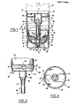
- the apparatus comprises a body 1 of generally cylindrical shape, this body however being slightly flared upward to allow demolding.
- the lower end of the body 1 forms an annular base 2.
- a brewing chamber 3 and above, an oil tank 4.
- the brewing chamber 3 is limited by a bottom 6 which has a concavity directed towards the oil tank 4.
- the bottom 6 is a substantially hemispherical bowl.
- a mechanical mixer 7 is mounted in rotation around the axis X-X of the apparatus, by means of a blind bearing 8 arranged in the center of the bowl 6, and a drive shaft 9 which passes through the oil tank 4 and is connected by means of a removable coupling 11 to an electric motor 12 mounted above the tank 4.
- the mixer 7 carries two blades 13, the lower cut of which follows the profile of the bowl 6. In the vicinity of their end, the blades 13 have an opening 14 favorable to the formation of emulsions.
- the reservoir 4 and the mixing chamber 3 are connected by a calibrated communication 16.
- the communication 16 is carried out by means of an oil flow regulator 15 comprising a well 17 through which the shaft d drive 9 of the mixer 7 with a calibrated radial clearance L.
- the upper end of the well 17 coincides with the maximum oil level 18 in the reservoir 4.
- the well 17 has an axially elongated lumen 21 which extends from the maximum level of oil 18 to a minimum level of oil 22 in the reservoir 4, and which makes the reservoir 4 communicate with the interior of the well 17.
- the well 17 opens into the stirring chamber 3, in the suction zone resulting from the centrifugal effect generated by the mechanical beater 7.
- the well 17 defines with a shoulder 19 carried by a flange 20 of the beater 7, an annular interstice g calibrated (Figure 5).
- the blades 13 of the mixer 7 each carry a fin 25 ( Figure 1) directed upwards to the level of the lower end of the well 17. The inner edge of the fins 25 is located in the immediate vicinity of the gap g .
- the tank 4 and the brewing chamber 3 are arranged on either side of a sliding separator 23.
- the separator 23 is a tank whose bottom 24 is conical so as to be sloping from its periphery towards the axis X-X of the device.
- the tank 23 also has a substantially cylindrical side wall 26, directed towards the tank 4 and adjacent to the body 1.
- the bottom 24 is provided at its center with a bore 27 intended to allow the substantially sealed sliding of the tank 23 relative to the well 17 .
- the bore 27 widens in a curved profile 28 to connect to the bottom 24 of the tank 23.
- the bore 27 is terminated by an annular surface 29 which, before the rotation of the beater 7 is in leaktight contact against the shoulder 19 of the beater 7, and thus closes the gap g.
- the separator 23 is also in substantially sealed abutment against a shoulder 31 formed on the internal wall of the body 1, substantially at a quarter of its height, at the junction of this wall with the bowl 6, and directed towards the reservoir 4 .
- the regulator 15 has a shoulder 32 directed towards the brewing chamber 3 and intended to serve as a stop for the separator 23 at the end of making the mayonnaise (FIG. 5).
- the regulator 15 comprises a sleeve 33 which covers the removable coupling 11.
- the sleeve 33 is integral with a cover 34 intended to protect the engine 12 against oil splashes.
- the cover 34 On its periphery, the cover 34 carries a double rim directed upwards 36, the lower part of which is fitted into the body 1 while the upper part 37 enlarged in steps is fitted around the motor 12.
- the lower part of the rim 36 has a projection 38 intended to cooperate with a recess 39 of corresponding shape of the body 1, so as to immobilize the body 1 in rotation relative to the regulator 15.
- the upper part 37 of the rim 36 has a notch 41 directed towards the motor 12 and intended to receive a push button 42 mounted on the lower edge of the motor 12, and directed towards the body 1.
- the button 42 controls the starting of the motor 12 when pressed.
- the notch 41 has a flat bottom 43 and two symmetrical inclined edges 44 and is deep enough for the button 42 to be in the position of maximum extension when it is opposite the bottom 43.
- the cover 34 is pierced with an oil filling orifice 46.
- the body 1, the regulator 15, and the separator 23 are made of plastic.
- the separator 23 is then placed in the bowl 6, with its bore 27 directed downwards, and it is pushed manually until it bears on the shoulder 19 of the mixer 7 and the shoulder 31 of the body 1 Thus, the basic ingredients are enclosed in the stirring chamber 3 made substantially sealed by the separator 23.
- the regulator 15 is put in place on the bowl 1, engaging the well 17 around the axis 9 and in the bore 27, until the flange 36 is fitted into the upper end of the body 1.
- the oil is poured through the orifice 46, into the reservoir 4, the bottom of which is formed by the conical bottom 24 of the separator 23.
- Some oil leaks may occur between the separator 23 and the shoulder 31 or between the separator 23 and the shoulder 19 taking into account the summary nature of the sealing means provided in these locations
- the air trapped between the bottom 24 of the separator 23 and the ingredients during filling the reservoir 4 considerably reduces the passage of oil to practically cancel it.
- the motor 12 is then fitted into the flange 37 by coupling it to the shaft 9 by means of the removable coupling 11 and taking care that the button 42 is opposite the notch 41.
- the motor 12 is slightly rotated about the axis XX, in one direction or the other with respect to the body 1. Therefore , the button 42 ( Figure 2) meets one of the oblique edges 44 of the notch 41, which pushes it into the body of the motor 12 to the position shown in dotted lines in Figure 2. This causes the setting running the engine safely tee, because if the engine 12 or the body 1 is released, these two members will return to their initial relative angular position, by extension of the button 42 resting on the inclined edge 44 of the notch 41. Furthermore, if the regulator 15 disengages from motor 12, this also causes the extension of button 42, therefore stopping motor 12.
- the ingredients contained in the stirring chamber 3 tend to move away from the axis X-X under the effect of the centrifugal force generated by the blades 13.
- the oil is mixed with the other ingredients by the mixer 7.
- the emulsion which begins to form tends to clump in the openings 14 of the blades 13, which considerably slows down the engine. launched from around 20,000 to 24,000 rpm up to the relatively slow speed of 3,500 to 4,000 rpm suitable for making mayonnaise. Due to the constant supply of oil, the mixture increases in volume and pushes the separator higher and higher.
- the engine 12 is stopped and the parts are dismantled one by one: the engine 12, the regulator 15, the separator 23 and the beater 7.
- the mayonnaise remains contained in the body 1.
- the device according to the invention is particularly compact thanks to its sliding separator, and also makes it possible to make the mayonnaises in a particularly fast and safe manner. Indeed, the mayonnaise during manufacture being confined in a chamber 3 whose volume is just sufficient, it is avoided that a certain amount of the mixture is sprayed on walls where it would escape mixing. As the separator 23 rises, it is less and less subjected to the upward forces originating from the centrifugation of the mixture, but this reduction is compensated by the causes the amount of oil hanging over the separator 23 to also decrease.
- the apparatus according to the invention provides an oil supply whose regularity is remarkable.
- the mayonnaise is prepared very quickly, in 7 to 30 seconds for a mayonnaise of approximately 150 g. It can also be noted - that before the start of stirring the side wall 26 of the separator 23 is very close to the internal wall of the body 1 and this proximity contributes to sealing between the separator 23 and the shoulder 31.
- the wall 26 When the separator 23 has taken off from the shoulder 31, the wall 26 is more and more distant from the internal wall of the body 1, because of the slight flaring of the body 1 necessary to allow the latter to be molded. This effect is very favorable, because once the separator 23 has taken off, the suction through the interstitial space becomes preponderant and the sealing around the separator 23 becomes less important. On the contrary, it is preferable for an oil film to be interposed between the wall 26 and the body 1 to allow it to slide smoothly.
Landscapes
- Engineering & Computer Science (AREA)
- Chemical & Material Sciences (AREA)
- Chemical Kinetics & Catalysis (AREA)
- Mechanical Engineering (AREA)
- Food Science & Technology (AREA)
- Seasonings (AREA)
- Food-Manufacturing Devices (AREA)
- Mixers Of The Rotary Stirring Type (AREA)
- Accessories For Mixers (AREA)
Priority Applications (1)
| Application Number | Priority Date | Filing Date | Title |
|---|---|---|---|
| AT82401220T ATE20817T1 (de) | 1981-07-31 | 1982-06-30 | Geraet zum zubereiten von mayonnaisen oder aehnlichen emulsionen. |
Applications Claiming Priority (2)
| Application Number | Priority Date | Filing Date | Title |
|---|---|---|---|
| FR8114917A FR2510387A1 (fr) | 1981-07-31 | 1981-07-31 | Appareil pour confectionner les mayonnaises ou emulsions analogues |
| FR8114917 | 1981-07-31 |
Publications (2)
| Publication Number | Publication Date |
|---|---|
| EP0071496A1 true EP0071496A1 (de) | 1983-02-09 |
| EP0071496B1 EP0071496B1 (de) | 1986-07-23 |
Family
ID=9261040
Family Applications (1)
| Application Number | Title | Priority Date | Filing Date |
|---|---|---|---|
| EP82401220A Expired EP0071496B1 (de) | 1981-07-31 | 1982-06-30 | Gerät zum Zubereiten von Mayonnaisen oder ähnlichen Emulsionen |
Country Status (8)
| Country | Link |
|---|---|
| US (1) | US4439043A (de) |
| EP (1) | EP0071496B1 (de) |
| JP (1) | JPS5912286B2 (de) |
| AT (1) | ATE20817T1 (de) |
| CA (1) | CA1175666A (de) |
| DE (2) | DE71496T1 (de) |
| ES (1) | ES514556A0 (de) |
| FR (1) | FR2510387A1 (de) |
Cited By (3)
| Publication number | Priority date | Publication date | Assignee | Title |
|---|---|---|---|---|
| FR2593377A1 (fr) * | 1986-01-30 | 1987-07-31 | Moulinex Sa | Appareil de preparation de mayonnaise ou sauce analogue |
| WO1996025079A1 (de) * | 1995-02-13 | 1996-08-22 | Braun Aktiengesellschaft | Stabmixer, zum rühren oder zerkleinern von nahrungsmitteln und behälter für einen stabmixer |
| EP0856273A1 (de) * | 1997-02-03 | 1998-08-05 | Braun Aktiengesellschaft | Deckel zum Verschliessen eines Arbeitsbehälters |
Families Citing this family (6)
| Publication number | Priority date | Publication date | Assignee | Title |
|---|---|---|---|---|
| US4511255A (en) * | 1984-04-30 | 1985-04-16 | Dci, Inc. | Clean-in-place agitator assembly |
| GB2194165B (en) * | 1986-08-21 | 1990-02-14 | Hung Bu Shein | An automatic egg-beater |
| DE10031753A1 (de) * | 2000-06-29 | 2002-01-17 | Braun Gmbh | Arbeitsbehälter zum Aufnehmen und Bearbeiten von Nahrungsmitteln |
| JP5419263B2 (ja) * | 2009-05-27 | 2014-02-19 | 株式会社貝印刃物開発センター | 攪拌具 |
| FR3068587B1 (fr) * | 2017-07-07 | 2020-06-05 | Seb S.A. | Appareil de preparation culinaire pour la realisation d'emulsions |
| US20200353428A1 (en) * | 2019-05-09 | 2020-11-12 | Lifetime Brands, Inc. | Emulsification module for use with a food processor |
Citations (7)
| Publication number | Priority date | Publication date | Assignee | Title |
|---|---|---|---|---|
| DE619780C (de) * | 1935-10-07 | Metallwarenfabrik Robert Koch | Mit Drillspindelantrieb und Speiseoelbehaelter versehenes Geraet zum Anruehren von Mayonnaise | |
| FR1087875A (fr) * | 1953-02-03 | 1955-03-01 | Diviseur-mélangeur | |
| FR1089420A (fr) * | 1953-12-14 | 1955-03-17 | Perfectionnements aux appareils émulsionneurs | |
| FR1092758A (fr) * | 1953-03-04 | 1955-04-27 | Appareil ménager tel que mélangeur-batteur | |
| GB777271A (en) * | 1954-12-08 | 1957-06-19 | Uberto Pinto | An improved mixing and emulsifying apparatus |
| US2932494A (en) * | 1958-10-17 | 1960-04-12 | Nathaniel B Wales | Vibratory whipping device |
| FR2474853A1 (fr) * | 1980-01-31 | 1981-08-07 | Seb Sa | Appareil menager pour emulsionner des produits alimentaires |
Family Cites Families (3)
| Publication number | Priority date | Publication date | Assignee | Title |
|---|---|---|---|---|
| US1253394A (en) * | 1917-09-05 | 1918-01-15 | Robert C Lambie | Churn-dasher. |
| US3164303A (en) * | 1961-12-04 | 1965-01-05 | Semco Res Inc | Storage and mixing cartridge |
| US3289897A (en) * | 1966-03-15 | 1966-12-06 | Royal London Ltd | Combined agitator and fluid mover |
-
1981
- 1981-07-31 FR FR8114917A patent/FR2510387A1/fr active Granted
-
1982
- 1982-06-30 EP EP82401220A patent/EP0071496B1/de not_active Expired
- 1982-06-30 DE DE198282401220T patent/DE71496T1/de active Pending
- 1982-06-30 AT AT82401220T patent/ATE20817T1/de not_active IP Right Cessation
- 1982-06-30 DE DE8282401220T patent/DE3272136D1/de not_active Expired
- 1982-07-01 US US06/394,472 patent/US4439043A/en not_active Expired - Fee Related
- 1982-07-05 CA CA000406606A patent/CA1175666A/en not_active Expired
- 1982-07-30 ES ES514556A patent/ES514556A0/es active Granted
- 1982-07-31 JP JP57133001A patent/JPS5912286B2/ja not_active Expired
Patent Citations (7)
| Publication number | Priority date | Publication date | Assignee | Title |
|---|---|---|---|---|
| DE619780C (de) * | 1935-10-07 | Metallwarenfabrik Robert Koch | Mit Drillspindelantrieb und Speiseoelbehaelter versehenes Geraet zum Anruehren von Mayonnaise | |
| FR1087875A (fr) * | 1953-02-03 | 1955-03-01 | Diviseur-mélangeur | |
| FR1092758A (fr) * | 1953-03-04 | 1955-04-27 | Appareil ménager tel que mélangeur-batteur | |
| FR1089420A (fr) * | 1953-12-14 | 1955-03-17 | Perfectionnements aux appareils émulsionneurs | |
| GB777271A (en) * | 1954-12-08 | 1957-06-19 | Uberto Pinto | An improved mixing and emulsifying apparatus |
| US2932494A (en) * | 1958-10-17 | 1960-04-12 | Nathaniel B Wales | Vibratory whipping device |
| FR2474853A1 (fr) * | 1980-01-31 | 1981-08-07 | Seb Sa | Appareil menager pour emulsionner des produits alimentaires |
Cited By (6)
| Publication number | Priority date | Publication date | Assignee | Title |
|---|---|---|---|---|
| FR2593377A1 (fr) * | 1986-01-30 | 1987-07-31 | Moulinex Sa | Appareil de preparation de mayonnaise ou sauce analogue |
| EP0233515A1 (de) * | 1986-01-30 | 1987-08-26 | Moulinex S.A. | Gerät zum Zubereiten von Mayonnaisen oder ähnlichen Sossen |
| WO1996025079A1 (de) * | 1995-02-13 | 1996-08-22 | Braun Aktiengesellschaft | Stabmixer, zum rühren oder zerkleinern von nahrungsmitteln und behälter für einen stabmixer |
| US5810472A (en) * | 1995-02-13 | 1998-09-22 | Braun Aktiengesellschaft | Hand blender for mixing or comminuting foodstuffs with an air supply structure |
| EP0856273A1 (de) * | 1997-02-03 | 1998-08-05 | Braun Aktiengesellschaft | Deckel zum Verschliessen eines Arbeitsbehälters |
| US6000650A (en) * | 1997-02-03 | 1999-12-14 | Braun Aktiengesellschaft | Lid for closing a processing container |
Also Published As
| Publication number | Publication date |
|---|---|
| JPS5827532A (ja) | 1983-02-18 |
| JPS5912286B2 (ja) | 1984-03-22 |
| DE71496T1 (de) | 1983-05-11 |
| FR2510387A1 (fr) | 1983-02-04 |
| EP0071496B1 (de) | 1986-07-23 |
| ES8305573A1 (es) | 1983-04-16 |
| US4439043A (en) | 1984-03-27 |
| CA1175666A (en) | 1984-10-09 |
| DE3272136D1 (en) | 1986-08-28 |
| FR2510387B1 (de) | 1983-12-09 |
| ES514556A0 (es) | 1983-04-16 |
| ATE20817T1 (de) | 1986-08-15 |
Similar Documents
| Publication | Publication Date | Title |
|---|---|---|
| EP1978855B1 (de) | Kochvorrichtung mit rührmittel und entsprechendes verfahren | |
| EP2433525B1 (de) | Dampfgarer und mixer | |
| EP1656866A1 (de) | Vorrichtung und Verfahren zur Zubereitung von Schaum aus einem flüssigen Milchprodukt | |
| EP1855542A1 (de) | Doppelwandiger behälter für eiskalte zubereitungen und eismaschine mit einem derartigen behälter | |
| FR2503990A1 (fr) | Procede pour confectionner de la glace comestible allegee, en particulier au moyen d'une sorbetiere de menage et appareil, de preference, appareil menager utilisable a cette fin | |
| EP0324115B1 (de) | Mixstab für Haushaltszwecke | |
| EP2355681A1 (de) | Elektrische vorrichtung zur herstellung und zum kochen von sojamilch, fruchtsäften oder pürees | |
| EP0071496B1 (de) | Gerät zum Zubereiten von Mayonnaisen oder ähnlichen Emulsionen | |
| EP0328590B2 (de) | Zusatzbehälter für küchenmaschinen | |
| FR2487661A1 (fr) | Machine a cafe electrique comportant un filtre en forme de tambour de centrifugation | |
| FR2513104A1 (fr) | Cafetiere electrique comportant un filtre centrifuge | |
| EP1139838B1 (de) | Mehrzweckküchenmaschine | |
| FR2780261A1 (fr) | Dispositif melangeur perfectionne pour distributeur automatique de boissons chaudes | |
| EP1483997B1 (de) | Rotierende Arbeitsvorrichtung zur Zubereitung von Getränken in einem Küchengerät | |
| EP0043773A1 (de) | Gerät zum Behandeln von Nahrungsmitteln, insbesondere von teigförmigen Massen | |
| EP3912526B1 (de) | Rührblatt zum rühren von lebensmitteln für kochgerät und entsprechendes gerät | |
| EP2852305A1 (de) | Haushaltsvorrichtung und verfahren zur herstellung eines konzentrats aus einer flüssigkeit und von extrakten aus inhaltsstoffen pflanzlichen ursprungs | |
| EP2606778A1 (de) | Household appliance for preparing beverages comprising a working container and a filtration device | |
| EP3424382B1 (de) | Emulsion haushaltsgerät zur essenszubereitung | |
| FR2474853A1 (fr) | Appareil menager pour emulsionner des produits alimentaires | |
| FR2486773A1 (fr) | Sorbetiere perfectionnee a usage domestique | |
| FR3132290A1 (fr) | Compacteur domestique de contenants en matière plastique vides | |
| FR2748382A1 (fr) | Pied de mixage | |
| FR2537864A3 (fr) | Cafetiere electrique a filtre centrifuge | |
| BE545398A (de) |
Legal Events
| Date | Code | Title | Description |
|---|---|---|---|
| PUAI | Public reference made under article 153(3) epc to a published international application that has entered the european phase |
Free format text: ORIGINAL CODE: 0009012 |
|
| 17P | Request for examination filed |
Effective date: 19820703 |
|
| AK | Designated contracting states |
Designated state(s): AT BE CH DE GB IT LI NL |
|
| ITCL | It: translation for ep claims filed |
Representative=s name: BARZANO' E ZANARDO ROMA S.P.A. |
|
| TCAT | At: translation of patent claims filed | ||
| TCNL | Nl: translation of patent claims filed | ||
| DET | De: translation of patent claims | ||
| ITF | It: translation for a ep patent filed | ||
| GRAA | (expected) grant |
Free format text: ORIGINAL CODE: 0009210 |
|
| AK | Designated contracting states |
Kind code of ref document: B1 Designated state(s): AT BE CH DE GB IT LI NL |
|
| REF | Corresponds to: |
Ref document number: 20817 Country of ref document: AT Date of ref document: 19860815 Kind code of ref document: T |
|
| REF | Corresponds to: |
Ref document number: 3272136 Country of ref document: DE Date of ref document: 19860828 |
|
| PLBE | No opposition filed within time limit |
Free format text: ORIGINAL CODE: 0009261 |
|
| STAA | Information on the status of an ep patent application or granted ep patent |
Free format text: STATUS: NO OPPOSITION FILED WITHIN TIME LIMIT |
|
| 26N | No opposition filed | ||
| ITTA | It: last paid annual fee | ||
| PGFP | Annual fee paid to national office [announced via postgrant information from national office to epo] |
Ref country code: AT Payment date: 19940614 Year of fee payment: 13 |
|
| PGFP | Annual fee paid to national office [announced via postgrant information from national office to epo] |
Ref country code: GB Payment date: 19940621 Year of fee payment: 13 |
|
| PG25 | Lapsed in a contracting state [announced via postgrant information from national office to epo] |
Ref country code: GB Effective date: 19950630 Ref country code: AT Effective date: 19950630 |
|
| GBPC | Gb: european patent ceased through non-payment of renewal fee |
Effective date: 19950630 |
|
| PGFP | Annual fee paid to national office [announced via postgrant information from national office to epo] |
Ref country code: NL Payment date: 19970630 Year of fee payment: 16 |
|
| PGFP | Annual fee paid to national office [announced via postgrant information from national office to epo] |
Ref country code: CH Payment date: 19970707 Year of fee payment: 16 |
|
| PGFP | Annual fee paid to national office [announced via postgrant information from national office to epo] |
Ref country code: BE Payment date: 19970711 Year of fee payment: 16 |
|
| PGFP | Annual fee paid to national office [announced via postgrant information from national office to epo] |
Ref country code: DE Payment date: 19970826 Year of fee payment: 16 |
|
| PG25 | Lapsed in a contracting state [announced via postgrant information from national office to epo] |
Ref country code: LI Free format text: LAPSE BECAUSE OF NON-PAYMENT OF DUE FEES Effective date: 19980630 Ref country code: CH Free format text: LAPSE BECAUSE OF NON-PAYMENT OF DUE FEES Effective date: 19980630 Ref country code: BE Free format text: LAPSE BECAUSE OF NON-PAYMENT OF DUE FEES Effective date: 19980630 |
|
| BERE | Be: lapsed |
Owner name: SEB S.A. Effective date: 19980630 |
|
| PG25 | Lapsed in a contracting state [announced via postgrant information from national office to epo] |
Ref country code: NL Free format text: LAPSE BECAUSE OF NON-PAYMENT OF DUE FEES Effective date: 19990101 |
|
| REG | Reference to a national code |
Ref country code: CH Ref legal event code: PL |
|
| NLV4 | Nl: lapsed or anulled due to non-payment of the annual fee |
Effective date: 19990101 |
|
| PG25 | Lapsed in a contracting state [announced via postgrant information from national office to epo] |
Ref country code: DE Free format text: LAPSE BECAUSE OF NON-PAYMENT OF DUE FEES Effective date: 19990401 |