EP0071548A2 - Dampfkoch- und -sterilisiergerät - Google Patents
Dampfkoch- und -sterilisiergerät Download PDFInfo
- Publication number
- EP0071548A2 EP0071548A2 EP82420101A EP82420101A EP0071548A2 EP 0071548 A2 EP0071548 A2 EP 0071548A2 EP 82420101 A EP82420101 A EP 82420101A EP 82420101 A EP82420101 A EP 82420101A EP 0071548 A2 EP0071548 A2 EP 0071548A2
- Authority
- EP
- European Patent Office
- Prior art keywords
- steam
- chamber
- cooking chamber
- cooker according
- door
- Prior art date
- Legal status (The legal status is an assumption and is not a legal conclusion. Google has not performed a legal analysis and makes no representation as to the accuracy of the status listed.)
- Withdrawn
Links
Images


Classifications
-
- A—HUMAN NECESSITIES
- A47—FURNITURE; DOMESTIC ARTICLES OR APPLIANCES; COFFEE MILLS; SPICE MILLS; SUCTION CLEANERS IN GENERAL
- A47J—KITCHEN EQUIPMENT; COFFEE MILLS; SPICE MILLS; APPARATUS FOR MAKING BEVERAGES
- A47J27/00—Cooking-vessels
- A47J27/14—Cooking-vessels for use in hotels, restaurants, or canteens
- A47J27/16—Cooking-vessels for use in hotels, restaurants, or canteens heated by steam
-
- A—HUMAN NECESSITIES
- A23—FOODS OR FOODSTUFFS; TREATMENT THEREOF, NOT COVERED BY OTHER CLASSES
- A23B—PRESERVATION OF FOODS, FOODSTUFFS OR NON-ALCOHOLIC BEVERAGES; CHEMICAL RIPENING OF FRUIT OR VEGETABLES
- A23B2/00—Preservation of foods or foodstuffs, in general
- A23B2/30—Preservation of foods or foodstuffs, in general by heating materials in packages which are not progressively transported through the apparatus
Definitions
- the invention relates to a steam cooker-sterilizer of the type comprising a cooking chamber in which the dishes are cooked by steam produced by bringing water to a boil by means of a heat source.
- the cooking chamber also forms a steam production chamber, since the water necessary for this steam production is placed in the bottom of the cooking chamber where it is brought to the boil by a source of heat disposed in this chamber or acting below.
- the steam formed meets the cold wall of the cooking chamber which thus absorbs calories to the detriment of the dishes to be cooked and the speed of cooking.
- the object of the present invention is to provide a steam cooker which overcomes these drawbacks and makes it possible to obtain rapid pressurization of the cooking chamber, both when it is put into operation and to renew the steam, and leads to a reduction heating time, therefore a reduction in the amount of energy required to cook a dish.
- the cooking chamber on the one hand, is delimited by a cylindrical shell provided with a bottom and asso opposite, to this, to a watertight door and, on the other hand, is separated from the steam production chamber which, of annular shape, is delimited by two ferrules, respectively interior and exterior, communicates by its lower part with a water reserve and comprises, at least in its upper part, at least one nozzle capable of injecting steam into the cooking chamber when a heat source, acting at the lower part of the annular chamber , brings the water contained in it to a boil.
- the quantity of water, placed in the annular chamber for producing steam is reduced, which makes it possible to obtain, very quickly, steam under pressure which then penetrates through the nozzles into the cooking chamber.
- the walls of the cooking chamber are brought very quickly to the normal operating temperature, which considerably reduces the steam condensations on these walls on the cooking side, in the phase of operation of the cooker and during cooking.
- the steam injection nozzles consist of orifices of very small diameter, distributed substantially over the upper third of the inner shell and having a substantially radial longitudinal axis, so as to direct the steam directly into the area where the cook is placed.
- the cooker is composed of two ferrules, respectively interior 2 and exterior 3, delimiting between them an annular chamber 4 for producing steam.
- the ferrule 2 itself delimits the cooking chamber provided with means 6 for positioning a gril 7 intended to receive a container 8 containing the dish 2 which must be cooked.
- the cooking chamber 5 is closed by a flat bottom 10 provided with a collar 12 which fits on the end posterior of the ferrule 2.
- This bottom is associated with a convex bottom 13 also provided with a flange 14 coming to cover the flange 12 of the bottom 10.
- the chamber 15, thus produced, constitutes a reserve of water. It communicates with the outside by a water supply duct 16 provided with a tight screw cap 17 serving as a manual filling orifice.
- the chamber 15 communicates with the annular chamber 4 by a bent duct 18 disposed at its lower part. This duct is connected to an 18 'drain tube fitted with a tap and for descaling the cooker.
- the two ferrules 2 and 3 are connected by an annular spacer 11 sealingly sealing the annular chamber 4. Due to this construction, the width of the chamber 4 is very small, since it is equal to the thickness flanges 12 and 14. Its volume is therefore twenty to fifty times smaller than that inside of the cooking chamber 5.
- the source of heat necessary for the operation of this cooker, is constituted by an electrical resistance 19 pressed against the lower and outer part of the shell 3 of the annular chamber 4.
- the supply of this resistance is controlled by pressure switches 20 detecting the pressure prevailing respectively in the cooking 2 and steam production 4 chambers.
- a safety valve 21 protects the two chambers against any overpressure.
- This cooking chamber 2 is closed, at its front end, by a sealed door 22 disposed in a housing 23 of larger diameter than that of the cooking chamber 2 and formed by flaring of the inner shell 2.
- This door is shaped box and is formed by the association of a flat bottom 24, identical to that 10 of the cooking chamber, with a curved bottom 25 identical to that 13, and this so as to reduce the manufacturing cost of the cooker.
- the domed bottom 25 is provided locally with a peripheral groove 26 in which is housed a lip seal 27 ensuring the sealing of the closure by coming into contact with the wall of the housing.
- the operating handle 30 is integral in rotation with a shaft 35 freely mounted for rotation in a bearing 36 integral with the bottom 25.
- the hub 32 in the form of a housing, is mounted freely in rotation in a bearing 37 integral with the bottom 22. It also includes several radial arms 38 on which the locking rods 33 are articulated. in rotation between the shaft 35 and the case 32 is ensured by friction by means of an annular ring 40, of deformable material with a high coefficient of friction, disposed between the hub and the shaft and compressed by a threaded sleeve 42, friction adjustment.
- This friction drive constitutes a safety device against the unexpected opening of the pressurized device by not transmitting the rotational movement of the shaft 35 to the hub 32, when the rods 33 are pressed strongly against their keeper by all of the pressure exerted on the convex inner face of the door.
- the drive torque of the hub 32 is always adjusted to be less than the torque necessary to actuate the rods when the device is under pressure.
- the ends of these rods and the corresponding faces of the keepers are arranged to increase friction under the action of pressure. It is obvious that the rotation of the boot 32 is limited to a fraction of a turn by known stop means and not shown.
- the resistor 12 When the container 8 has been introduced into the cooking chamber 2 and the door 22 is closed, the resistor 12 is energized and immediately transmits its heat energy to the lower part of the inner shell 2. This energy heats the water 50 contained in the annular chamber 4 and very quickly ensures the formation of vapor 52 at the upper part of the annular chamber.
- the wall of the inner shroud 2 being provided with several series of very small orifices 53 constituting steam injection nozzles, the steam thus enters the cooking chamber in the form of jets oriented substantially radially in the direction of the container 8 and food 9.
- the pressure in the cooking chamber 5 exceeds a value considered to be the safety threshold and, for example, exceeds a bar
- the pressure switches 20 cut off the supply of the resistor 19, which leads to the instantaneous stop of the injection of steam, taking into account the small inertia of the bath. In known manner, this results in a drop in pressure in the cooking chamber 2 which is recorded by one of the pressure switches then triggering again the supply of the resistors 19. Under these conditions, and thanks to the large heating surface provided by the resistor 19 and the particular shape of the annular chamber, the vapor is reformed very quickly.
- the cooker thanks to a very short pressurization time and a very low restart inertia, makes it possible to reduce the cooking time and, consequently, the consumption of energy required.
- the safety valve 21 is arranged in the door 22. It is fixed on the bottom 25 and housed between this bottom and that 24. Thus, when the valve operates, the vapor does not escape into the atmosphere, but In the door, the water, obtained by condensation on the internal faces of the door, accumulates at the bottom of the latter, from where it is discharged by a bore 56. In one embodiment, this bore makes opposite the outlet orifice of a conduit 57, terminating in the drain conduit 18 '.
- the time necessary to cook 6 kilograms of potatoes, with a resistance of 2.5 kw, is eight minutes.
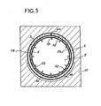
- the steam production chamber 4 is delimited between an external ferrule 2 and an internal ferrule 58 which is distinct from the internal ferrule 2 with which it delimits a diffusion chamber 59.
- the ferrule 58 has at least one transfer nozzle 60 which allows the vapor 52, formed in the chamber 4, to enter the diffusion chamber 59.
- This transfer nozzle has a diameter large enough so as not to create losses load increasing the pressure in the chamber 4.It can be associated with other nozzles of the same type.
- the ferrule 2, constituting the distribution ferrule comprises, over its entire periphery, injection nozzles 53 constituted by orifices of small diameter, so as to create losses load promoting the formation of steam jets as soon as it enters the diffusion chamber 59. Of course, the steam jets are directed radially.
- the steam produced in the chamber 4 is distributed uniformly throughout the cooking chamber, which contributes to accelerating the cooking of the food.
- this cooker can also be used as a sterilizer. It should be noted that, whatever its application, it makes it possible to arrange the products to be cooked or sterilized in almost all of its internal volume by using either to circular baskets, or to tiered racks.
- the different ferrules are represented as being coaxial, but it is obvious that they can be offset from one another.
Landscapes
- Engineering & Computer Science (AREA)
- Life Sciences & Earth Sciences (AREA)
- Food Science & Technology (AREA)
- Wood Science & Technology (AREA)
- Zoology (AREA)
- Chemical & Material Sciences (AREA)
- Polymers & Plastics (AREA)
- Cookers (AREA)
Applications Claiming Priority (2)
| Application Number | Priority Date | Filing Date | Title |
|---|---|---|---|
| FR8115234 | 1981-07-31 | ||
| FR8115234A FR2510359A1 (fr) | 1981-07-31 | 1981-07-31 | Cuiseur-sterilisateur a vapeur |
Publications (2)
| Publication Number | Publication Date |
|---|---|
| EP0071548A2 true EP0071548A2 (de) | 1983-02-09 |
| EP0071548A3 EP0071548A3 (de) | 1983-09-07 |
Family
ID=9261215
Family Applications (1)
| Application Number | Title | Priority Date | Filing Date |
|---|---|---|---|
| EP82420101A Withdrawn EP0071548A3 (de) | 1981-07-31 | 1982-07-13 | Dampfkoch- und -sterilisiergerät |
Country Status (2)
| Country | Link |
|---|---|
| EP (1) | EP0071548A3 (de) |
| FR (1) | FR2510359A1 (de) |
Cited By (4)
| Publication number | Priority date | Publication date | Assignee | Title |
|---|---|---|---|---|
| WO2006034705A1 (de) * | 2004-09-29 | 2006-04-06 | Roehrig Wilfried | Verfahren und vorrichtung zur industriellen herstellung von geschälten kartoffeln oder ähnlichen obst und gemüse mit verlängerter haltbarkeit |
| EP1691135A1 (de) * | 2005-01-20 | 2006-08-16 | Salvis AG | Gerät zum Dampfgaren von Nahrungsmitteln |
| CN115363414A (zh) * | 2022-06-24 | 2022-11-22 | 宁波方太厨具有限公司 | 一种具有锁门功能的蒸制烹饪装置 |
| CN115868783A (zh) * | 2022-12-30 | 2023-03-31 | 华帝股份有限公司 | 高效蒸汽发生器及烹饪设备 |
Family Cites Families (3)
| Publication number | Priority date | Publication date | Assignee | Title |
|---|---|---|---|---|
| FR691170A (fr) * | 1929-05-15 | 1930-10-02 | Perfectionnements aux autoclaves à double enveloppes | |
| US2659805A (en) * | 1949-07-11 | 1953-11-17 | Warren Alfred | Pressure cooker |
| SE332046B (sv) * | 1968-08-02 | 1971-01-25 | Svenska Medimekanik Ab | Dubbelmantlad snabbautoklav |
-
1981
- 1981-07-31 FR FR8115234A patent/FR2510359A1/fr not_active Withdrawn
-
1982
- 1982-07-13 EP EP82420101A patent/EP0071548A3/de not_active Withdrawn
Cited By (5)
| Publication number | Priority date | Publication date | Assignee | Title |
|---|---|---|---|---|
| WO2006034705A1 (de) * | 2004-09-29 | 2006-04-06 | Roehrig Wilfried | Verfahren und vorrichtung zur industriellen herstellung von geschälten kartoffeln oder ähnlichen obst und gemüse mit verlängerter haltbarkeit |
| EP1691135A1 (de) * | 2005-01-20 | 2006-08-16 | Salvis AG | Gerät zum Dampfgaren von Nahrungsmitteln |
| CN115363414A (zh) * | 2022-06-24 | 2022-11-22 | 宁波方太厨具有限公司 | 一种具有锁门功能的蒸制烹饪装置 |
| CN115363414B (zh) * | 2022-06-24 | 2023-06-20 | 宁波方太厨具有限公司 | 一种具有锁门功能的蒸制烹饪装置 |
| CN115868783A (zh) * | 2022-12-30 | 2023-03-31 | 华帝股份有限公司 | 高效蒸汽发生器及烹饪设备 |
Also Published As
| Publication number | Publication date |
|---|---|
| EP0071548A3 (de) | 1983-09-07 |
| FR2510359A1 (fr) | 1983-02-04 |
Similar Documents
| Publication | Publication Date | Title |
|---|---|---|
| EP0165187B1 (de) | Kochvorrichtung mit Dampfzuführung unter atmosphärischem Druck | |
| EP0251947B1 (de) | Dampfkochgerät mit Grillspiess | |
| EP3079530B1 (de) | Elektrische vorrichtung zum dampferwärmen und/oder garen von nahrungsmitteln | |
| EP1854383B1 (de) | Druckkochgerät zum Zubereiten von Nahrungsmitteln | |
| EP0323939B1 (de) | Dampferzeuger für Kochgeräte | |
| EP2433525B1 (de) | Dampfgarer und mixer | |
| EP3079529B1 (de) | Verfahren und vorrichtung zum erwärmen und/oder kochen von lebensmitteln mit dampf | |
| EP1535550A1 (de) | Druckgargerät mit Sicherheitsverriegelung des Deckels | |
| EP2277417B1 (de) | Dampfauslassorgan für Kochgerät, und mit einem solchen Organ ausgestattetes Kochgerät | |
| EP0872201B1 (de) | Elektrisch beheiztes Wassererhitzungsgerät | |
| FR2760619A1 (fr) | Bouilloire electrique avec canal a vapeur menant vers un detecteur de temperature ou de vapeur | |
| EP0071548A2 (de) | Dampfkoch- und -sterilisiergerät | |
| EP0451066B1 (de) | Dampferzeuger für Gargeräte mit Entwässerungseinrichtung | |
| EP1555919A1 (de) | Dampfherstellungsbasis für einen dampfkocher mit einem aromastoffträger | |
| EP1736085B1 (de) | Teigwarenkocher mit einem beweglichen Korb und Kochzustandsdetektor | |
| EP0673615A1 (de) | Dampf-Kochgerät | |
| EP0597748B1 (de) | Schnelldampferzeuger | |
| CH689608A5 (fr) | Machine à café électrique ménagère en particulier pour café expresso équipée d'un dispositif de préchauffage de tasses. | |
| EP0900542B1 (de) | Brühgerät | |
| EP0539299B1 (de) | Gargerät mit einer Kombination von Strahlungs- und Dampfheizung | |
| FR2539434A3 (fr) | Chaudiere pour la production de vapeur utilisable plus particulierement dans les fers a repasser a vapeur | |
| EP1153562A2 (de) | Haushaltsgerät zum automatischen Erhitzen einer in einem Behälter enthaltenen Flüssigkeit oder Produkt zu ihrer Anwendungstemperatur | |
| FR2867669A1 (fr) | Appareil de cuisson a systeme de vidange optimise | |
| FR2775883A1 (fr) | Appareil a infuser |
Legal Events
| Date | Code | Title | Description |
|---|---|---|---|
| PUAI | Public reference made under article 153(3) epc to a published international application that has entered the european phase |
Free format text: ORIGINAL CODE: 0009012 |
|
| AK | Designated contracting states |
Designated state(s): AT BE CH DE GB IT LI NL SE |
|
| PUAL | Search report despatched |
Free format text: ORIGINAL CODE: 0009013 |
|
| AK | Designated contracting states |
Designated state(s): AT BE CH DE GB IT LI NL SE |
|
| 17P | Request for examination filed |
Effective date: 19840306 |
|
| STAA | Information on the status of an ep patent application or granted ep patent |
Free format text: STATUS: THE APPLICATION IS DEEMED TO BE WITHDRAWN |
|
| 18D | Application deemed to be withdrawn |
Effective date: 19860131 |