EP0071686A2 - Frein monté à l'arrière d'un moulinet de pêche - Google Patents
Frein monté à l'arrière d'un moulinet de pêche Download PDFInfo
- Publication number
- EP0071686A2 EP0071686A2 EP81305932A EP81305932A EP0071686A2 EP 0071686 A2 EP0071686 A2 EP 0071686A2 EP 81305932 A EP81305932 A EP 81305932A EP 81305932 A EP81305932 A EP 81305932A EP 0071686 A2 EP0071686 A2 EP 0071686A2
- Authority
- EP
- European Patent Office
- Prior art keywords
- washer
- drag
- shaft
- disc
- housing
- Prior art date
- Legal status (The legal status is an assumption and is not a legal conclusion. Google has not performed a legal analysis and makes no representation as to the accuracy of the status listed.)
- Withdrawn
Links
Images


Classifications
-
- A—HUMAN NECESSITIES
- A01—AGRICULTURE; FORESTRY; ANIMAL HUSBANDRY; HUNTING; TRAPPING; FISHING
- A01K—ANIMAL HUSBANDRY; AVICULTURE; APICULTURE; PISCICULTURE; FISHING; REARING OR BREEDING ANIMALS, NOT OTHERWISE PROVIDED FOR; NEW BREEDS OF ANIMALS
- A01K89/00—Reels
-
- A—HUMAN NECESSITIES
- A01—AGRICULTURE; FORESTRY; ANIMAL HUSBANDRY; HUNTING; TRAPPING; FISHING
- A01K—ANIMAL HUSBANDRY; AVICULTURE; APICULTURE; PISCICULTURE; FISHING; REARING OR BREEDING ANIMALS, NOT OTHERWISE PROVIDED FOR; NEW BREEDS OF ANIMALS
- A01K89/00—Reels
- A01K89/02—Brake devices for reels
Definitions
- This invention relates to spinning reels and more particularly to the drag mechanisms associated therewith.
- the present invention is directed toward overcoming the problems heretofore associated with rear mounted drag mechanisms.
- the present invention sets forth a spinning reel incorporating a rear mounted drag with alternating, radially extending surfaces which rotate with the shaft and surfaces which are fixed within the reel housing against rotation. Selectively exerting a bias causes the aforementioned surfaces to frictionally interfere with one another and thereby exert a braking or dragging effect against rotation of the shaft.
- FIG. 1 an open face style fishing reel 1 is shown in an exploded perspective view.
- the reel 1 having a housing 10 which includes an integral gear case 28, a stem 12 which connects the housing 10 to a mounting foot 11 which is used to attach the reel to a spinning style fishing rod.
- the reel includes a crank assembly 40 rotatable about a crank handle shaft 41 with a rotatable winding handle 44 for use by a fisherman with his left hand for line retrieval while the rod (not shown) is being held by his right hand.
- the handle 44 ' may be disposed on-the other side of the gear case 28 to accommodate the personal desires of the user.
- An axially mounted rotor housing 230 is provided and adapted to rotate about the axis of the central spool shaft 300 as the crank 40 is turned for line retrieval with the line 5 being captured by the bail 270 passing over the line roller 272.
- the bail 270 and the line roller 272 rotate with rotor 230 and the fishing line 5 is thereby wound on the spool 290.
- the screws 281 function as pivot points and are accordingly the centers of rotation of the bail 270 via the bail arms 260 and 280.
- An oscillator mechanism 30 causes the spool 290 to reciprocate axially back and forth as the rotor 230 winds a line 5 about the spool 290; but as in spinning reels generally, the spool 290 does not rotate about the axis of the central shaft 300 except as controllably permitted by the adjustable drag mechanism 50.
- Such limited rotation of the spool may occur during line retrieval when a fish is on the other end of the line 5 fighting for its life while still in the water; and, thus the force of the drag friction is overcome by tension in the line. This is a feature that prevents the internal mechanism from being destroyed when a large fish is on the end of the line 5.
- the bail 270 When the bail 270 is swung to an open position for casting, the line 5 may freely pay out from the spool 290.
- a side cover plate 14 is secured to the housing 10 to cover the gear housing 28 which includes a drag pocket 13 and is accomplished by means of screws 17.
- the drive gear assembly 150 includes a drive gear 153 that is mounted on the drive gear shaft 154 and : is received at one end in the side lip 136 of cam 130.
- Bearing collar 131 is coaxial. with the lip 136 and mounted on the opposite side of the cam surface 133.
- the gear assembly 150 and the oscillator cam 130 each have an internal hold and are coaxially mounted on the crank handle 41 with the drive shaft 154 externally mounted in the side plate bearing 15 and the bearing collar 131 mounted in a bearing 16 that is part of the side of the housing 10 and coaxial with bearing 15 (but now shown in Fig. 1).
- Oscillator slide yoke 140 surrounds cam surface 133 of the cam assembly 130 and is slidably mounted near the bearing 16 in the gear case 28.
- Retainer screw 42 secures the crank handle shaft 41 to the reel 1.
- the crank. assembly 40 can be removed from the reel 1 and reversed so that the reel 1 can be held by a fisherman in his left hand and cranked by his right hand.
- Pinion assembly 60 is mounted in the front hold 29 of the front face 25 and surrounded by bearing 70 which is kept in place by retainer 72.
- Mounted inside the gear case 28 on the pinion assembly 60 is the self-centering ratchet 67.
- a spacer ring 74 and a trip lever retainerf76 are mounted on the pinion 60.
- the rotor 230 is mounted on the pinion assembly 60 in front of retainer 2 76 and is secured thereto by means of washer 61 and nut 62.
- Center spool shaft 300 is rotatably mounted in and supported by the pinion assembly hole 64 with the back end 301 thereof extending past the partition 20 into the drag assembly 50.
- the spool 290 is mounted on the shaft 300 and secured thereto by means of spool cap 292.
- the shaft 300 is secured to the oscillator yoke slide 140 and reciprocates back and forth relative to the rotor when the crank handle shaft 41 rotates.
- Pinion gear 63 mounted at the back of the pinion assembly 60 mates with the drive gear 153 and is rotatable thereby.
- the pinion assembly 60 in turn causes the rotor 230 to rotate about the spool 290. Because the oscillator cam assembly 30 and the gear drive assembly 150 are both operated by the crank assembly 40 at the same time, the spool 290 reciprocates back and forth relative to the rotational motion of the line roller 272 about the spool and by this cooperative movement the line 5 is wound around the spool 290.
- the axis of the rotor 230, shaft 300, pinion assembly 60, and drag assembly 50 is approximately perpendicular to the axis 3 of the crank handle assembly 40, oscillator mechanism 30 and the drive gear assembly 150.
- the axis 2 is located above the axis 3 being nearer to the foot 11.
- the bail 270 is normally stored in the "closed” or “retrieve” position whereby the line roller 272 functions to wind the line 5 about the spool 290 by turning the handle 44 relative to the reel 1.
- the bail 270 is pivoted about the L-shaped bail ears 231 and 232 and locked in place by the trip lever 220 that is received by the cam 261 and trip ramp 264 surfaces located on the underside of the bail arm 260 (not shown in Fig. 1); the underside of bail arm 260 faces into the cavity of the ear 231.
- the line 5 In the casting position, the line 5 is free to pay out from the spool 290. During casting, this pay out of the line is quite rapid, thus, the fisherman using this open faced style fishing reel is obligated to use his finger to snub the line to arrest the pay out since neither the rewind or line retrieval mode (the winding of the line about the spool 90 by the line roller 272) or the drag mechanism 50 is operational.
- the rotor 230 In order to change the bail from the "open" casting position to the "closed” rewind or retrieve position, the rotor 230 is rotated causing the trip lever 220 to disengage from the trip ramp 264 permitting the bail return springs 283 and 284 to pivot the bail 270 back to the retrieve position.
- a self-centering bail mechanism is shown that permits the rotation of the rotor 230 to the same position for opening the bail 270 at the optimum casting position.
- a self-centering lever arm 350 is mounted within the gear case by means of screw 351 and washer 352 with the back end 354 of the arm 350 in operable engagement with the self-centering button 80.
- the lever arm spring 353 mounted on the drive gear shaft 154 urges the pawl end 355 toward the ratchet 67. But, with the button 80 in the back position, the pawl 355 is pivoted out of engagement with the ratchet 67.
- the bottom of the button 80 permits the pawl end 355 of the arm 350 to come into contact with the ratchet 67 so that the rotor 230 can be rotated "backwards" (counter to the direction of rotation for winding the line around the spool) to a preselected position for opening the bail at the casting position.
- the same mechanism acts as an anti- reverse device for the reel so that the rotor can only be rotated "backward” less than one revolution.
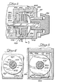
- FIGs. 1 through 5 an embodiment of the rear mounted drag mechanism 50 of this invention is illustrated.
- the reel housing 10 has located therein a partition 400 opposed by a rear wall 401 of the reel housing 10.
- the partition 400 and rear wall 401 are separated by a flat troughed bottom 402, a pair of opposing sidewalls 404 and a top 406 all of which cooperate to form a drag pocket 13 to house the drag mechanism 50.
- the partition 400 has a shaft accommodating center bore 408 larger in diameter than the shaft 300, extending therethrough having a first countersink 410 and a larger diameter second countersink 411 directed toward the drag pocket 13.
- the rear wall 401 of the drag pocket 13 has a threaded bore 412 coaxial with the center bore 408 of the partition 400 to receive a threaded post 414 having attached thereto outer, manually manipulable knob 416.
- the drag mechanism 50 includes a disc-shaped base bushing 418.
- the base bushing 418 is of a diameter to freely rotate within the drag pocket 13 and has a coaxial boss 420 which is received into and piloted by the second countersink 411.
- Axially extending through the base bushing 418 is a bushing bore 422 of a diameter to register with the first countersink 410.
- the face of the base bushing 418 opposing the boss 420 is perpendicular to the axis of the shaft 300 and in cooperation with the bushing bore 422 defines an annular bushing face 423.
- the shaft 300 of the reel 1 extends axially through the center bore 408, through the drag pocket 13 and terminates in the region of the threaded bore 412 in the rear wall 401.
- a cylindrical coupling 424 Keyed to the shaft 300 for relative axial movement therealong and rotation therewith is a cylindrical coupling 424.
- the keying of the coupling 424 to the shaft 300 may be provided by cooperative splining such as the double "D" splines as illustrated in the drawings particularly Figs. 2 and 4.
- the coupling 424 is smaller in diameter than, and is disposed for the most part within, the bushing bore 422 and, in its forwardmost position abuts the bottom of the first countersink 410.
- the end of the coupling 424 opposing the partition 400 has four radially outward extending slots 426. For ease of assembly, the slots 426 are of equal size and are equally spaced about the end of the coupling 424.
- the drag driver 428 Connected to the coupling 424 for rotation therewith is a drag driver 428.
- the drag driver 428 has a cylindrical driver body 430 with four fingers 432 at one end thereof matingly received by the slots 426.
- the driver body 430 has an outer diameter slightly larger than that of the coupling 424 and is closely received and piloted for rotation with the shaft 300 by the bushing bore 422.
- a driver bore 433 axially extends through the driver body to pass the shaft 300 without engagement thereof.
- the drag driver 428 Contiguous to the base bushing 418 the drag driver 428 has a radially outward extending-disc 434.
- the disc 434 is of a diameter similar to that of the base bushing 418 so as not to interferingly engage the boundaries of the drag pocket 13.
- the opposing annular surfaces of the disc 434 define drag faces 436.
- a drag washer 438 Keyed to the end of the drag driver body 430 opposing the fingers 432 for rotation therewith as by cooperative splining is a drag washer 438.
- the drag washer 438 is spaced from the disc 434 of the drag driver 428 and, due to the aforementioned splining rotates with the drag driver 420 while, at .the same time, being movable along the splined portion of the drag driver body 430.
- the forward stationary washer 440 is rectangular or square and has a base 442 to mate with the troughed bottom 402 of the drag pocket 13.
- a washer bore 444 Centrally located in the forward stationary washer 440 is a washer bore 444 to receive the drag driver body 430 for rotation therein. From the foregoing it follows that the forward stationary washer 440 may move axially with respect to the shaft 300 either toward or away from the drag driver disc 434 but is restrained by the bottom 402 against rotation.
- a rear stationary washer 446 Located close to drag washer 438 and to the rear thereof (to right as viewed in Fig. 3) is a rear stationary washer 446.
- the rear stationary washer 446 is identical in structure and function to the forward stationary washer 440 and in cooperation therewith spans the drag washer 438.
- friction washer 448 Interposed between the base bushing 418 and the drag driver disc 434 is a friction washer 448. Likewise similar friction washers 448 are interposed between the drag driver disc 434 and forward stationary washer 440 and between the drag washer 438 and the aforementioned forward and rear stationary washers 440 and 446.
- the friction washers 448 have outer diameters comparable to that of the disc 434 and base bushing 418 and have axial holes to permit free relative rotation between the drag driver body 430 and the friction washers 448.
- the spring washer 450 Abutting the rear stationary washer 446 is a spheroid spring washer 450.
- the spring washer 450 has an axial spring bore 452 to pass the shaft 300 and a plurality of radial apertures 454 directed therefrom subjected to an axial force.
- the threaded post 414 abuts the spring washer 450 in the vicinity of the spring bore 452.
- Manual turning of the knob 416 to reduce or increase the drag forces the post 414 bears against and somewhat deforms the spring washer 450 in the region provided by the apertures 454. This in turn selectively exerts a bias upon the rear stationary washer 446.
- the drag knob 416 In the release, or no drag position, the drag knob 416 is disposed at its outermost position such that the threaded. post 414 does not forcibly bear against the spring washer 450. In this position the coupling 424 and connected drag driver 428 are free to axially move along the shaft 300. The base bushing 418, drag washer 438, friction washers 448 and forward and rear stationary washers 440 and 446 are likewise free to move axially upon the driver body 430. Accordingly, the aforementioned elements, as the shaft 300 rotates : to pay out fishing line, become axially positioned so as to minimize frictional interengagement and freely permit shaft 300 rotation.
- the drag mechanism 50 is actuated by the manual rotation of the knob 416 causing the post 414 to forcibly bear against the spring washer 450.
- the spring washer 450 engages the rear stationary washer 446 and to axially collapse the drag mechanism 50.
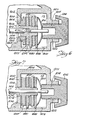
- FIGs. 6 and 7 further embodiments of the rear mounted drag assembly 50 for a fishing reel 1 are shown. Similar parts have the same reference numerals.
- the center bore 408 in the partition 400 is of a size to receive a disc-shaped, stepped base bushing 460.
- a first cylindrical : stepped portion 462.of the base bushing 460 extends into and is piloted by the bore 408 of the partition 400.
- a second stepped portion 464 of the base bushing 460 is received into and piloted by a coaxial countersink 466 formed in the partition 460.
- the remainder of the base bushing 460 extends radially outward of the second stepped portion 464.
- An axial bushing bore 422 in the base bushing 460 larger in diameter than the shaft 300, passes the shaft 300 therethrough.
- a drag driver 468 Keyed to the shaft 300 for rotation therewith and for axial movement, as by double "D" splines, is a drag driver 468 having a cylindrical body 470 of a diameter to axially register with the bushing bore 422 and having a radially extending outward peripheral disc 434. As seen in Fig. 6 the driver body 470 has a cylindrical driver bore 472 the rear portion of which, i.e., opposing the partition 400, is splined to mate with the splined shaft 300. In this manner the frictional resistance to relative axial movement between the shaft 300 and drag driver 428 is minimized.
- FIG. 7 Yet a further embodiment of the drag mechanism 50 depicted in Fig. 7, has the partition 400 provided with a center bore 408 to receive and pilot a drag driver 474 having the disc 434, and more particularly its cylindrical body 476.
- a friction washer 448 separates the drag driver disc 434 from the partition 400 and upon imposition of the drag frictionally engages the partition 400 and the disc 434 to, in cooperation with the remainder of the drag mechanism 50, exert a braking or drag : effect upon the shaft 300.
- frictionally engaging elements may be incorporated in the drag mechanism for lighter or heavier duty reels.
Landscapes
- Life Sciences & Earth Sciences (AREA)
- Environmental Sciences (AREA)
- Animal Husbandry (AREA)
- Biodiversity & Conservation Biology (AREA)
Applications Claiming Priority (2)
| Application Number | Priority Date | Filing Date | Title |
|---|---|---|---|
| US29006181A | 1981-08-04 | 1981-08-04 | |
| US290061 | 1981-08-04 |
Publications (2)
| Publication Number | Publication Date |
|---|---|
| EP0071686A2 true EP0071686A2 (fr) | 1983-02-16 |
| EP0071686A3 EP0071686A3 (fr) | 1983-07-20 |
Family
ID=23114380
Family Applications (1)
| Application Number | Title | Priority Date | Filing Date |
|---|---|---|---|
| EP81305932A Withdrawn EP0071686A3 (fr) | 1981-08-04 | 1981-12-17 | Frein monté à l'arrière d'un moulinet de pêche |
Country Status (4)
| Country | Link |
|---|---|
| EP (1) | EP0071686A3 (fr) |
| JP (1) | JPS5823734A (fr) |
| KR (1) | KR830006877A (fr) |
| CA (1) | CA1170237A (fr) |
Cited By (2)
| Publication number | Priority date | Publication date | Assignee | Title |
|---|---|---|---|---|
| AU638884B2 (en) * | 1991-02-05 | 1993-07-08 | Shimano Inc. | Drag control structure for baitcasting reel |
| EP1712127A1 (fr) * | 2005-04-15 | 2006-10-18 | Shimano Inc. | Mécanisme de freinage pour moulinet de pêche |
Families Citing this family (2)
| Publication number | Priority date | Publication date | Assignee | Title |
|---|---|---|---|---|
| JPS6046882U (ja) * | 1983-09-08 | 1985-04-02 | 株式会社シマノ | 釣用リ−ルのドラッグ機構 |
| KR870003503Y1 (ko) * | 1985-06-24 | 1987-10-16 | 주식회사 은성사 | 낚시용 릴의 드랙 시스템 |
Family Cites Families (10)
| Publication number | Priority date | Publication date | Assignee | Title |
|---|---|---|---|---|
| US3126167A (en) * | 1964-03-24 | Kiyomi ide | ||
| US2910253A (en) * | 1954-08-31 | 1959-10-27 | Urfabriken Ab | Fishing reels |
| US2863617A (en) * | 1955-07-20 | 1958-12-09 | Sears Roebuck & Co | Spinning type fishing reel |
| US3074664A (en) * | 1960-01-11 | 1963-01-22 | Lionel Corp | Closed face spinning reel |
| US3222009A (en) * | 1963-08-08 | 1965-12-07 | Pflueger Corp | Spinning reel |
| JPS5059294U (fr) * | 1973-10-09 | 1975-06-02 | ||
| JPS5110151U (fr) * | 1974-07-11 | 1976-01-24 | ||
| SE7706721L (sv) * | 1977-06-09 | 1978-12-10 | Abu Ab | Haspelrulle |
| US4200248A (en) * | 1978-08-11 | 1980-04-29 | Brunswick Corporation | Internal disc drag for spinning reel |
| US4371124A (en) * | 1979-10-18 | 1983-02-01 | Brunswick Corporation | Drag system for spinning style fishing reel |
-
1981
- 1981-11-30 CA CA000391209A patent/CA1170237A/fr not_active Expired
- 1981-12-17 EP EP81305932A patent/EP0071686A3/fr not_active Withdrawn
- 1981-12-22 KR KR1019810005054A patent/KR830006877A/ko not_active Abandoned
- 1981-12-28 JP JP56215998A patent/JPS5823734A/ja active Granted
Cited By (3)
| Publication number | Priority date | Publication date | Assignee | Title |
|---|---|---|---|---|
| AU638884B2 (en) * | 1991-02-05 | 1993-07-08 | Shimano Inc. | Drag control structure for baitcasting reel |
| EP1712127A1 (fr) * | 2005-04-15 | 2006-10-18 | Shimano Inc. | Mécanisme de freinage pour moulinet de pêche |
| US7232087B2 (en) | 2005-04-15 | 2007-06-19 | Shimano Inc. | Spinning reel drag mechanism |
Also Published As
| Publication number | Publication date |
|---|---|
| EP0071686A3 (fr) | 1983-07-20 |
| CA1170237A (fr) | 1984-07-03 |
| KR830006877A (ko) | 1983-10-12 |
| JPS5823734A (ja) | 1983-02-12 |
| JPH0220215B2 (fr) | 1990-05-08 |
Similar Documents
| Publication | Publication Date | Title |
|---|---|---|
| US4549702A (en) | Drag for spinning reel | |
| US4323203A (en) | Selective anti-reverse mechanism | |
| US4676450A (en) | Quick bail opening system for fishing reel | |
| US4509705A (en) | Surfcasting spinning reel | |
| EP0429923A1 (fr) | Mécanisme de freinage pour moulinet de pêche | |
| US4426045A (en) | Bail trip mechanism for fishing reel | |
| CA1161012A (fr) | Systeme de freinage pour moulinet de peche | |
| USRE47184E1 (en) | Fishing reel with improved line management and control system and clicker mechanism | |
| US4402469A (en) | Self-aligning drag drive for fishing reels | |
| US5199665A (en) | Electronic bait alert for a fishing reel | |
| US2633307A (en) | Casting reel | |
| US5542619A (en) | Fishing reel of the multiplier type | |
| US3381914A (en) | Spinning reel with brake | |
| US4359197A (en) | Silent-selective anti-reverse mechanism | |
| EP0071686A2 (fr) | Frein monté à l'arrière d'un moulinet de pêche | |
| US4545545A (en) | Drag for spinning reels | |
| US5040743A (en) | Spinning reel with rear-actuated front drag | |
| US4200248A (en) | Internal disc drag for spinning reel | |
| US5358196A (en) | Drag mechanism for a spinning reel | |
| US4522347A (en) | Drag adjustment click spring assembly | |
| US3006573A (en) | Spinning reel | |
| US4824040A (en) | Quick bail opening system for fishing reel | |
| US4523726A (en) | Anti-reverse mechanism | |
| CA1040607A (fr) | Bobines de filature a face aveugle | |
| US3488015A (en) | Fishing reel |
Legal Events
| Date | Code | Title | Description |
|---|---|---|---|
| PUAI | Public reference made under article 153(3) epc to a published international application that has entered the european phase |
Free format text: ORIGINAL CODE: 0009012 |
|
| AK | Designated contracting states |
Designated state(s): DE FR GB IT SE |
|
| PUAL | Search report despatched |
Free format text: ORIGINAL CODE: 0009013 |
|
| AK | Designated contracting states |
Designated state(s): DE FR GB IT SE |
|
| STAA | Information on the status of an ep patent application or granted ep patent |
Free format text: STATUS: THE APPLICATION IS DEEMED TO BE WITHDRAWN |
|
| 18D | Application deemed to be withdrawn |
Effective date: 19840321 |
|
| RIN1 | Information on inventor provided before grant (corrected) |
Inventor name: COUNCILMAN, RICHARD R. |