EP0071726A2 - Dispositif de protection du ruban encreur - Google Patents
Dispositif de protection du ruban encreur Download PDFInfo
- Publication number
- EP0071726A2 EP0071726A2 EP82105480A EP82105480A EP0071726A2 EP 0071726 A2 EP0071726 A2 EP 0071726A2 EP 82105480 A EP82105480 A EP 82105480A EP 82105480 A EP82105480 A EP 82105480A EP 0071726 A2 EP0071726 A2 EP 0071726A2
- Authority
- EP
- European Patent Office
- Prior art keywords
- ribbon
- splice
- movement
- printing
- accordance
- Prior art date
- Legal status (The legal status is an assumption and is not a legal conclusion. Google has not performed a legal analysis and makes no representation as to the accuracy of the status listed.)
- Granted
Links
Images

Classifications
-
- B—PERFORMING OPERATIONS; TRANSPORTING
- B41—PRINTING; LINING MACHINES; TYPEWRITERS; STAMPS
- B41J—TYPEWRITERS; SELECTIVE PRINTING MECHANISMS, i.e. MECHANISMS PRINTING OTHERWISE THAN FROM A FORME; CORRECTION OF TYPOGRAPHICAL ERRORS
- B41J33/00—Apparatus or arrangements for feeding ink ribbons or like character-size impression-transfer material
- B41J33/02—Ribbon arrangements
- B41J33/10—Arrangements of endless ribbons
-
- B—PERFORMING OPERATIONS; TRANSPORTING
- B41—PRINTING; LINING MACHINES; TYPEWRITERS; STAMPS
- B41J—TYPEWRITERS; SELECTIVE PRINTING MECHANISMS, i.e. MECHANISMS PRINTING OTHERWISE THAN FROM A FORME; CORRECTION OF TYPOGRAPHICAL ERRORS
- B41J35/00—Other apparatus or arrangements associated with, or incorporated in, ink-ribbon mechanisms
- B41J35/36—Alarms, indicators, or feed disabling devices responsive to ink ribbon breakage or exhaustion
Definitions
- This invention relates to ribbon protection devices for printers and relates more particularly to a system to detect a s;moce o, e,dmess robbp, as wemm as a ribbon jam.
- an endless ribbon and a stuffer box to provide a low cost ribbon system.
- the stuffer box is used to store the excess ribbon in the ribbon loop, this excess being fed or "stuffed” into the box.
- the ribbon splice area is less able to withstand print forces than the rest of the ribbon, thereby resulting in a high likelihood of ribbon failure at the splice area if printing is attempted on this area.
- U.S. 3,949,856 shows the use of a roller mechanism to detect medium movement to indicate medium jams. However, this reference does not show the detection of ribbon splice and ribbon jam.
- the present invention employs sensing means which engages the moving ribbon and senses a characteristic thereof in the vicinity of the splice, such as an opening in the ribbon near the splice. Sensing of this characteristic is employed to suspend printing while the splice area passes through the print station. As an additional feature of the invention, the duration of time during which the characteristic is sensed is used to determine whether a splice is approaching the print station or whether this duration indicates that the ribbon motion has stopped as a result of a ribbon jam.
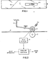
- a portion of an endless ribbon 11 is shown, with a splice therein as indicated at lla joining the ends.
- ribbon 11 is transported past a print station containing one or more print mechanisms which contact ribbon 11 to produce print characters on a suitable medium. It is in the area of this splice that printing is to be avoided because of poor inking properties and the potential for damage to the splice by the print mechanism, as discussed above.
- the present invention provides an opening llb in ribbon 11 spaced slightly from splice lla. Opening llb may be either ahead of or behind splice lla in the direction of ribbon motion, depending on the position of the sensing means relative to the print station.
- the presence or absence of this opening at a predetermined point in the ribbon travel path can be sensed to suspend printing while splice lla and opening llb pass the print station.
- the same sensing means can be employed to detect lack of ribbon motion indicative of a ribbon jam, or to stop the printer.
- sensing wheel 12 may be employed to ride on ribbon 11. Wheel 12 may be urged against ribbon.11 and an underlying idler wheel 13 by a spring means 14 so that wheel 12 rotates with movement of ribbon 11.
- Sensing wheel 12 may be of any suitable type capable of producing some type of output signal in response to its rotation and to provide a different or no output signal when it is not rotating. Examples of suitable types of such wheels are optical disks having slits therein for the passage of light therethrough to produce a train of detectable light pulses as the wheel rotates, as shown in Fig. 2 and as is well known in the art. Alternatively, the wheel may produce magnetic pulses during rotation which can be converted to signals denoting motion of the wheel and hence of ribbon 11, as shown in FIG. 4.
- Fig. 2 the light pulses passing through the slits in wheel 12 as it rotates are sensed by a light pulse detector 16 which produces an output signal indicating that ribbon motion has been detected.
- a light pulse detector 16 which produces an output signal indicating that ribbon motion has been detected.
- circuitry 17 which measures any gaps or missing pulses in the output from detector 12.
- circuitry 17 operates normally.
- circuitry 17 senses the duration of this cessation of pulses, and if the cessation period corresponds to the predetermined length of time required for opening llb in ribbon 11 to pass under sensing wheel 12, circuitry 17 indicates to the printer controls that the ribbon splice is approaching the print station so that printing will be suspended while opening llb and splice lla pass the print station.
- circuitry 17 indicates this condition to cause printing and ribbon drive to be halted and an error condition indicator to be raised.
- FIG. 4 illustrates an alternate embodiment of the invention employing magnetic sensing to detect ribbon motion and opening llb in ribbon 11.
- ribbon 11 includes a splice lla on which it is undesirable to print.
- Ribbon motion is sensed by means including a knurled magnet drive wheel 21 which is rotatably mounted on a shift 22.
- Drive wheel 21 engages ribbon 11 and rotates on shaft 22 as the ribbon moves.
- the lower end of shaft 22 carries a magnet 23 which rotates with shaft 22 and cooperates magnetically with a detector 24, such as a Hall effect detector, which produces an output signal indicative of rotation of magnet 23 and hence of motion of ribbon 11.
- a detector 24 such as a Hall effect detector
- the output from detector 24 is supplied to circuitry which is operable to determine if a gap appears in the detector output and if this gap exceeds a predetermined length of time.
- a gap appears in the detector output and if this gap exceeds a predetermined length of time.
- the predetermined length gap is detected, corresponding to opening llb passing drive wheel 21, printing is suspended while splice lla and opening llb pass the print station. If the gap in the detector signal exceeds the predetermined length, indicating that the ribbon motion has stopped because of a jam, print head motion drive and ribbon motion drive are stopped until the problem is corrected.
- the present invention provides a simple technique for detecting both the ribbon splice and a ribbon jam, to extend the life of the ribbon and to add to the quality and reliability of the printing system.
Landscapes
- Impression-Transfer Materials And Handling Thereof (AREA)
Applications Claiming Priority (2)
| Application Number | Priority Date | Filing Date | Title |
|---|---|---|---|
| US289584 | 1981-08-03 | ||
| US06/289,584 US4376587A (en) | 1981-08-03 | 1981-08-03 | Print ribbon protection |
Publications (3)
| Publication Number | Publication Date |
|---|---|
| EP0071726A2 true EP0071726A2 (fr) | 1983-02-16 |
| EP0071726A3 EP0071726A3 (en) | 1984-01-11 |
| EP0071726B1 EP0071726B1 (fr) | 1987-01-14 |
Family
ID=23112164
Family Applications (1)
| Application Number | Title | Priority Date | Filing Date |
|---|---|---|---|
| EP82105480A Expired EP0071726B1 (fr) | 1981-08-03 | 1982-06-23 | Dispositif de protection du ruban encreur |
Country Status (5)
| Country | Link |
|---|---|
| US (1) | US4376587A (fr) |
| EP (1) | EP0071726B1 (fr) |
| JP (1) | JPS5822193A (fr) |
| CA (1) | CA1182064A (fr) |
| DE (1) | DE3275071D1 (fr) |
Cited By (2)
| Publication number | Priority date | Publication date | Assignee | Title |
|---|---|---|---|---|
| EP0713783A1 (fr) * | 1994-11-25 | 1996-05-29 | BULL HN INFORMATION SYSTEMS ITALIA S.p.A. | Cassette de ruban encreur sans fin avec épissure de ruban protegée et son dispositif de protection |
| DE29701808U1 (de) * | 1997-02-03 | 1997-12-11 | PSi Printer Systems international GmbH, 57080 Siegen | Farbbandkassette für Schreibgeräte, insbesondere für Matrixdrucker |
Families Citing this family (4)
| Publication number | Priority date | Publication date | Assignee | Title |
|---|---|---|---|---|
| JPS61115675U (fr) * | 1984-12-29 | 1986-07-22 | ||
| US4878773A (en) * | 1988-06-08 | 1989-11-07 | Ncr Corporation | Ribbon feed control apparatus and method |
| JPH0741387Y2 (ja) * | 1992-09-08 | 1995-09-27 | 株式会社タニコーテック | ブラケット部可動式棚 |
| JP4278885B2 (ja) * | 2000-05-25 | 2009-06-17 | 富士フイルム株式会社 | インクジェットプリンタ |
Family Cites Families (5)
| Publication number | Priority date | Publication date | Assignee | Title |
|---|---|---|---|---|
| DE2258546C2 (de) * | 1972-11-29 | 1982-10-21 | Siemens AG, 1000 Berlin und 8000 München | Einrichtung zur Papiervorschubüberwachung bei Druckern |
| GB1499152A (en) * | 1975-02-05 | 1978-01-25 | Xerox Corp | Typewriter ribbon cassette |
| DE2512259A1 (de) * | 1975-03-20 | 1976-09-30 | Siemens Ag | Vorrichtung zur richtungsumschaltung der farbbandbewegung in mechanischen druckeinrichtungen |
| US4268182A (en) * | 1976-09-28 | 1981-05-19 | Citizen Watch Co., Ltd. | Device for detecting travel condition of inkribbon for printers |
| DE2646336C3 (de) * | 1976-10-14 | 1979-06-28 | Triumph Werke Nuernberg Ag, 8500 Nuernberg | Farbbandtransportvorrichtung |
-
1981
- 1981-08-03 US US06/289,584 patent/US4376587A/en not_active Expired - Fee Related
-
1982
- 1982-05-20 JP JP57084102A patent/JPS5822193A/ja active Granted
- 1982-06-17 CA CA000405398A patent/CA1182064A/fr not_active Expired
- 1982-06-23 EP EP82105480A patent/EP0071726B1/fr not_active Expired
- 1982-06-23 DE DE8282105480T patent/DE3275071D1/de not_active Expired
Cited By (3)
| Publication number | Priority date | Publication date | Assignee | Title |
|---|---|---|---|---|
| EP0713783A1 (fr) * | 1994-11-25 | 1996-05-29 | BULL HN INFORMATION SYSTEMS ITALIA S.p.A. | Cassette de ruban encreur sans fin avec épissure de ruban protegée et son dispositif de protection |
| US5601374A (en) * | 1994-11-25 | 1997-02-11 | Bull Hn Information Systems Italia S.P.A. | Endless ink ribbon cartridge with protected ribbon splice, and a protection arrangement therefor |
| DE29701808U1 (de) * | 1997-02-03 | 1997-12-11 | PSi Printer Systems international GmbH, 57080 Siegen | Farbbandkassette für Schreibgeräte, insbesondere für Matrixdrucker |
Also Published As
| Publication number | Publication date |
|---|---|
| EP0071726A3 (en) | 1984-01-11 |
| US4376587A (en) | 1983-03-15 |
| JPS5822193A (ja) | 1983-02-09 |
| JPS6363394B2 (fr) | 1988-12-07 |
| EP0071726B1 (fr) | 1987-01-14 |
| CA1182064A (fr) | 1985-02-05 |
| DE3275071D1 (en) | 1987-02-19 |
Similar Documents
| Publication | Publication Date | Title |
|---|---|---|
| US4177731A (en) | Printer system ribbon drive having constant ribbon speed and tension | |
| EP0875392A1 (fr) | Imprimantes de type navette et méthodes pour sa mise en oeuvre | |
| CA1249172A (fr) | Commande pour imprimantes matricielles utilisees dans des conditions ambiantes rigoureuses | |
| EP0071726B1 (fr) | Dispositif de protection du ruban encreur | |
| US5105363A (en) | Servo means for document-transport | |
| US4537125A (en) | Endless drive belt apparatus for processing card tickets with magnetic track | |
| US5405069A (en) | Paper motion detection system | |
| CA1116724A (fr) | Entrainement de ruban a vitesse et tension constantes pour imprimante | |
| US5230573A (en) | Printer with upstream sensor used to determine paper empty condition | |
| US5515088A (en) | Method and device for controlling the paper feed in a processor-driven printer | |
| US4878773A (en) | Ribbon feed control apparatus and method | |
| US4268182A (en) | Device for detecting travel condition of inkribbon for printers | |
| US5900639A (en) | Apparatus for detecting the presence and speed of a record medium | |
| US5682039A (en) | Media position sensing system having a plurality of apertures in the media edge margin | |
| EP1423712B1 (fr) | Systeme de detection de mouvement de ruban d'imprimante | |
| JPS5859096A (ja) | 無端帯状物体の寿命検出装置 | |
| US5084626A (en) | Servo for controlling document transport | |
| US20070229569A1 (en) | Printer carriage jam or stall detection | |
| US6961118B2 (en) | Continuous paper feed system | |
| JPS56137484A (en) | Printer | |
| JPS5957784A (ja) | プリンタのリボンフイ−ド検出装置 | |
| US5404425A (en) | Pen operability checking system for vector plotters | |
| US5027702A (en) | Print drum with alignment marks | |
| JPS6192874A (ja) | プリンタのキヤリツジ位置検出機構 | |
| JP2578920B2 (ja) | プリンタの印字位置決め機構 |
Legal Events
| Date | Code | Title | Description |
|---|---|---|---|
| PUAI | Public reference made under article 153(3) epc to a published international application that has entered the european phase |
Free format text: ORIGINAL CODE: 0009012 |
|
| AK | Designated contracting states |
Designated state(s): DE FR GB IT |
|
| 17P | Request for examination filed |
Effective date: 19830621 |
|
| PUAL | Search report despatched |
Free format text: ORIGINAL CODE: 0009013 |
|
| AK | Designated contracting states |
Designated state(s): DE FR GB IT |
|
| GRAA | (expected) grant |
Free format text: ORIGINAL CODE: 0009210 |
|
| AK | Designated contracting states |
Kind code of ref document: B1 Designated state(s): DE FR GB IT |
|
| PG25 | Lapsed in a contracting state [announced via postgrant information from national office to epo] |
Ref country code: IT Free format text: LAPSE BECAUSE OF FAILURE TO SUBMIT A TRANSLATION OF THE DESCRIPTION OR TO PAY THE FEE WITHIN THE PRESCRIBED TIME-LIMIT;WARNING: LAPSES OF ITALIAN PATENTS WITH EFFECTIVE DATE BEFORE 2007 MAY HAVE OCCURRED AT ANY TIME BEFORE 2007. THE CORRECT EFFECTIVE DATE MAY BE DIFFERENT FROM THE ONE RECORDED. Effective date: 19870114 |
|
| REF | Corresponds to: |
Ref document number: 3275071 Country of ref document: DE Date of ref document: 19870219 |
|
| ET | Fr: translation filed | ||
| PLBE | No opposition filed within time limit |
Free format text: ORIGINAL CODE: 0009261 |
|
| STAA | Information on the status of an ep patent application or granted ep patent |
Free format text: STATUS: NO OPPOSITION FILED WITHIN TIME LIMIT |
|
| 26N | No opposition filed | ||
| PGFP | Annual fee paid to national office [announced via postgrant information from national office to epo] |
Ref country code: GB Payment date: 19920506 Year of fee payment: 11 |
|
| PGFP | Annual fee paid to national office [announced via postgrant information from national office to epo] |
Ref country code: FR Payment date: 19920601 Year of fee payment: 11 |
|
| PGFP | Annual fee paid to national office [announced via postgrant information from national office to epo] |
Ref country code: DE Payment date: 19920619 Year of fee payment: 11 |
|
| PG25 | Lapsed in a contracting state [announced via postgrant information from national office to epo] |
Ref country code: GB Effective date: 19930623 |
|
| GBPC | Gb: european patent ceased through non-payment of renewal fee |
Effective date: 19930623 |
|
| PG25 | Lapsed in a contracting state [announced via postgrant information from national office to epo] |
Ref country code: FR Effective date: 19940228 |
|
| PG25 | Lapsed in a contracting state [announced via postgrant information from national office to epo] |
Ref country code: DE Effective date: 19940301 |
|
| REG | Reference to a national code |
Ref country code: FR Ref legal event code: ST |