EP0071753A2 - Gerät zum scharfen Abbilden von Information auf einem Film mittels eines geladenen Teilchenstrahles - Google Patents
Gerät zum scharfen Abbilden von Information auf einem Film mittels eines geladenen Teilchenstrahles Download PDFInfo
- Publication number
- EP0071753A2 EP0071753A2 EP82105891A EP82105891A EP0071753A2 EP 0071753 A2 EP0071753 A2 EP 0071753A2 EP 82105891 A EP82105891 A EP 82105891A EP 82105891 A EP82105891 A EP 82105891A EP 0071753 A2 EP0071753 A2 EP 0071753A2
- Authority
- EP
- European Patent Office
- Prior art keywords
- film
- platen
- gate
- volume
- predetermined
- Prior art date
- Legal status (The legal status is an assumption and is not a legal conclusion. Google has not performed a legal analysis and makes no representation as to the accuracy of the status listed.)
- Granted
Links
Images


Classifications
-
- G—PHYSICS
- G11—INFORMATION STORAGE
- G11B—INFORMATION STORAGE BASED ON RELATIVE MOVEMENT BETWEEN RECORD CARRIER AND TRANSDUCER
- G11B23/00—Record carriers not specific to the method of recording or reproducing; Accessories, e.g. containers, specially adapted for co-operation with the recording or reproducing apparatus ; Intermediate mediums; Apparatus or processes specially adapted for their manufacture
- G11B23/50—Reconditioning of record carriers; Cleaning of record carriers ; Carrying-off electrostatic charges
- G11B23/502—Reconditioning of record carriers; Cleaning of record carriers ; Carrying-off electrostatic charges of tape carriers
-
- G—PHYSICS
- G01—MEASURING; TESTING
- G01D—MEASURING NOT SPECIALLY ADAPTED FOR A SPECIFIC VARIABLE; ARRANGEMENTS FOR MEASURING TWO OR MORE VARIABLES NOT COVERED IN A SINGLE OTHER SUBCLASS; TARIFF METERING APPARATUS; MEASURING OR TESTING NOT OTHERWISE PROVIDED FOR
- G01D15/00—Component parts of recorders for measuring arrangements not specially adapted for a specific variable
- G01D15/14—Optical recording elements; Recording elements using X-or nuclear radiation
-
- G—PHYSICS
- G11—INFORMATION STORAGE
- G11B—INFORMATION STORAGE BASED ON RELATIVE MOVEMENT BETWEEN RECORD CARRIER AND TRANSDUCER
- G11B9/00—Recording or reproducing using a method not covered by one of the main groups G11B3/00 - G11B7/00; Record carriers therefor
- G11B9/10—Recording or reproducing using a method not covered by one of the main groups G11B3/00 - G11B7/00; Record carriers therefor using electron beam; Record carriers therefor
-
- H—ELECTRICITY
- H04—ELECTRIC COMMUNICATION TECHNIQUE
- H04N—PICTORIAL COMMUNICATION, e.g. TELEVISION
- H04N1/00—Scanning, transmission or reproduction of documents or the like, e.g. facsimile transmission; Details thereof
- H04N1/23—Reproducing arrangements
Definitions
- This invention relates to charged particle beam recording on a film as disclosed in U.S. Application Serial No. 023,548 and more specifically to an improved system and film gate for more accurately producing an image on an electron sensitive film with an electron beam.
- Such systems find particular utility in the graphic recording industry and provide accurate andn high resolution imaging.
- electron beam recording is especially useful for, producing computer output microfilms (COM), mass data storage, wide bandwidth signal recording, satellite photography, automated cartography as well as computer micrographic and seismic re- ording.
- COM computer output microfilms
- mass data storage wide bandwidth signal recording
- satellite photography automated cartography as well as computer micrographic and seismic re- ording.
- Essential elements of an electron beam.recorder include an electron gun, an electromagnetic focusing and deflection system, an electron sensitive film and a film gate.
- the electron beam traces or plots an image in the recording area on the emulsion side of a stationary electron sensitive film accurately positioned in ; the film gate.
- Electron beam recording is conducted in a vacuum atmosphere because air can scatter or attenuate the electron beam.
- a three stage vacuum system is used in an electron beam recorder system with the volume with highest vacuum containing the electron gun, a lower vacuum volume containing a beam path to the emulsion side of the recording film and the lowest vacuum in the-volume containing the film dispenser and transport mechanisms.
- This three stage vacuum system provides for rapid access to the film for the easy changing or replacement thereof.
- these distortions limit its value.
- the differential pressure exerted on the film by the three stage vacuum can adversely affect the shape of the film because it creates variable and unpredictable buckling of the film in the film gate.
- the film may be further distorted by air entrapped behind the film that may originate from the outgassing of water vapor or other atmospheric con- stitutents contained in the film or by. air which is transported by the film from the lower vacuum volume into the film gate as the film is-advanced to provide freshfilm for exposure.
- an EBR film gate can be made having a film receiving surface shaped to a predetermined configuration, so as to precisely positon a recording film along a predetermined continuous curvature.
- the continuously curved film gate may also include a means for continuously and uniformly tensioning the recording film to confom the film to the predetermined continuous curvature of the film gate.
- the distortions which have heretofor caused instabilities and uncertainties in the position of the recording film have been eliminated and the film is controlled so that these distortions conform to a known geometric form and are thereby made predictable.
- the electron beam is electronically controlled to compensate for these predictable and known geometric distortions to create an essentially geometrically distortionless image on the recording film.
- the present invention overcomes the buble like distortion problems associated with films employed in prior EBR film gates by ventilating the volume behind the film as it lies on the film receiving surface of the film gate platen to prevent the trapping of air between the film and the film receiving surface. More particularly, in a preferred embodiment, the portion of the film gate platen receiving the rear surface of the film is ventilated to the higher vacuum that is present on the forward side of the film to equalize the pressure applied to the front and rear film surfaces and eliminate the pressure differential across the film which can otherwise trap air or gas between the film and the platen and cause unpredictable and irregular film distortion.
- the present invention thus provides an improved vented and pressure equalizing film gate which more precisely locates a film therein and more accurately positions a film relative to a charged particle beam.
- the invention also provides for an improved EBR recording system which uses an improved vented and pressure equalized film gate to provide for the more accurate imaging of information on a charged particle sensitive film.
- the present invention is useable in combination with platens which impart various predetermined curvatures to the film, which curvatures can be simple or compound, of fixed or variable radii, concave or convex, along the length or width of the film or any other continuous configuration.
- the film gate of the present invention provides a ventilated platen of predetermined curvature along a prespecified length of film and a predetermined force to hold the film in contact with the ventilated film platen.
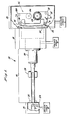
- Fig.1 illustrate a preferred embodiment of a complete charged particle beam recorder system generally designated 10.
- the complete electron beam recorder (EBR) includes a vacuum housing which can be divided into four volumes 14, 16, 18 and 20. Section 14 is reduced to a high vacuum atmosphere by vacuum stage A (for instance 10 -7 Torr) volumes 16 and 18 are reduced to lesser vacuum atmospheres by vacuum stage B -(for instance 10 -5 Torr) and volume 20 is reduced to a still lesser vacuum atmosphere by vacuum stage C (for instance 10 -1 Torr).
- the vacuum atmosphere produced by vaccum stages A, B and C can be established by. for instance conventional vacuum pumps.
- a charged particle recording beam is produced in the high vacuum-volume 14 by a charged particle emitter 22 such as a conventional high resolution triode electron gun 22 having a directly heated-thermionic emitter contained therein.
- High vacuum volume 14 is separated from the lesser vacuum volume 16 by for instance a partition wall 24 having a beam aperture therethrough.
- the vacuum section 16 provides for electromagnetic control of the beam by for instance three electromagnetic coils 26, 28, and 30 which in a preferred embodiment at least partially surround the beam path through the vacuum volume 16.
- the electromagnetic coils 26 and 28 center and focus the beam while the electromagnetic coil 30 for instance deflects the beam to effect for instance image plotting or tracing by the beam.
- Conventional electronic methods can be used to alter control signals applied to coil 30 to correct the beam deflection to compensate for known geometric distortions of a recording surface such as a curved electron sensitive film 32 to thereby produce the desired information image on the film.
- the vacuum volume 18 provided by stage B provides additional vacuum space in which to accomodate the deflected particle beam produced by the gun 22.
- the vacuum volume 20 provided by stage C contains a film transport gate mechanism generally indicated at 31 and a film gate indicated generally at 34, illustrated in more detail in Figs.2 and 5.
- the film gate 34 is between the higher and lower vacuum volumes 18, 20 respectively and is constructed and arranged to accurately position a charged particle sensitive recording means such as an electron sensitive emulsion coated film 32 in predetermined relation to the particle gun 22.
- the film 32 can be a conventional type such as that available from Eastman Kodak under the designation SO 219.
- the film gate transport means 31, advances the film from the lower vacuum volume 20 into the film gate 34 and the higher vacuum volume 18 as will be described hereinafter.
- Al electron.beam striking the film 32 causes a chemical change in the film, which, with further conventional treatment, can be developed to produce a desired information image.
- EBR recording is particularly suited to high resolution photography such as satellite or scanner data displays where a large number of high quality pictures are produced at electronic speeds.
- Computer controlled EBR recording systems offer particular advantages for the study and investigation of hydrology, geology, ecology, agriculture, meteorology, cartography, and land use.
- Particular EBR systems can provide data handling capacities for (1) high image throughout (2) on-line corrections of geometric and radiometric errors caused by the sensor-and satellite position (3) on-line annotating and framing of the continuous stream sensor date; (4) high image resolution and dynamic range; and (5) dramatic time and cost-reductions associated with eliminating the need to reformat and computer process, off-line, the raw sensor data for each image to obtain a radiometrically and geometrically corrected image.
- the EBR system is also useful for automated cartography to produce map products by the various recording techniques such as vector plotting, names and text compositions, or rester scanning.
- Image formats can be varied depending upon the film size and film transport used.
- EBR recording provides total composition and plotting capabilities compatible with any one or a mixture of sources to enable the production of high energy quality graphics such as line work, alphanumerics, symbols/trade- marks, or graphic arts quality type.
- Any film format can be utilized with a micrographics EBR for such film recording applications as micropublishing, business data computer output micrographics (COM), engineering drawings and seismic-data display.
- the various recording and production capabilities of the EBR system 10 depend heavily on the accurate, stable and defined.positioning of the film 32 in a known relationship with the film gate 34 and the charged particle beam produced by-the gun 22.
- the charged particle beam is sensitive to molecular particle scattering and hence it is highly desirable to dispose the beam impact face of the recording film 32 within a vacuum atmosphere to avoid such scattering.
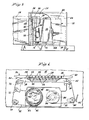
- FIG.2 an elevational perspective view of a preferred embodiment of the vented, pressure equalizing film gate 34 of the present invention is shown to be comprised of a film frame 36 and film platen 38.
- the film frame 36 has a forward reference surface 40 for positioning the frame 36, the gate 34 and the film 32 carried therein relative to the charged particle gun 22.
- the frame 36 has also a rear surface 42 for defining a film path between the frame 36 and platen 38.
- the frame 36 further includes an exposure aperture 44 therethrough from the forward reference surface 40 through the rear surface 42.
- the platen 38 has a film receiving surface generally designated at 46 boardered by a non film receiving surface 48.
- the surface 48 acts as the principal barrier between the higher pressure volume 18 due to stage C and the lower pressure volume 20 from stage B.
- the film receiving surface 46 of the platen 38 is separated from the rear surface 42 of the frame 36 by approximately two film thicknesses thus defining a film path therebetween having a means for film ingress 50 and means film egress 52.
- the means for ingress 50 is defined by the lead edges of the film palten.38 and the frame 36 while the means for egress 52 is defined by the trailing surface of the platen 38 and frame 36. Accordingly, as new film 32 is advanced through the film gate 34 it is exposed to a high vacuum applied from vacuum volume 18 within the film gate 34 through the frame aperture 44. Therefore there is a higher vacuum applied to the face surface of the film 32 within the film gate 34 than is applied to the film in the vacuum 20.
- the effect of the condition is that as new film is advanced into the gate 34 and stopped at the imaging position, air, from vacuum volume 20, is carried behind the film 32 into the film gate 34 between the receiving surface 46 and the barrier surface 48. This air behind the film 32 in the film gate 34, unless otherwise vented, can cause a bubble like bulge in the film toward the beam.
- the platen 38 of the present invention is provided with a means for pressure relieving the platen film receiving surface 46 whereby the pressure across the film 32 is equalized and the platen 38 has less surface area against which air or gas, can be trapped between the back of the film 32 and the platen 38.
- the means for pressure relieving the platen 38 should neither detract from nor interfere with the ability.of the platen 38 to impart a predetermined continuous curvature to a film 32 carried thereon.
- the film gate 34 is provided with a means 54 for venting the film receiving surface 46 which is recessed in the surface of-the platen 38 and is connected in pressure relieving relation to an atmosphere applied to the forward film surface.
- the means 54 for venting comprises a plurality of grooves disposed in the film receiving surface 46 of the platen 38 which extends into the non film receiving surface 48 of the platen 38 and an orifice 58 through the frame 36 adjacent the extended portions 56 of the grooves 54 disposed-in the non film receiving surface 48 of the platen 38 to thereby provide a through connection between the pressure atmosphere applied to the forward.film surface and the rear surface of the film residing on the platen 38.
- the plurality of parallel grooves 54 are disposed in the film receiving surface 46 of the platen 38 in a direction perpendicular to the direction of film travel through the film gate 34.
- the film platen 38 has two, 0,635 cm (one quarter inch) wide grooves per 2,54 cm (inch).
- the venting of the film receiving surface 46 of the platen 38 reduces the surface area of the overall film receiving surface 46 of the platen 38.
- the present invention gate 34 positions the film 32 in a pressure equalized manner to eliminate a pressure gradient across the film. Accordingly, it is preferred that theplaten film receiving surface 46 be vented to the atmosphere applied to the beam face of the film 32.
- Gases present on the emulsion face of the film are easily dissipated by the higher vacuum volume 18 in contact with the emulsion face of the film 32.
- gases carried on the rear surface of the film 32 can-often become trapped between the film 32 and the platen 38 as a bubble which introduce distortions in the disposition of the film 32 and thereby impair the accuracy of the beam imaging. It is therefore desirable to vent the film receiving surface 46 of the platen 38 to the high vacuum volume 18 continguous with the film face.
- Fig.3 film 32 enters the film gate 34 through passage between the curved frame 36 and the juxtaposed curved platen 38.
- the opposed film surfaces 42 and 46 of the curved frame 36 and curved platen 38 respectively are spaced such that the electron sensitive film 32 is relatively free to move along its length but is prevented from substantial motion towards or away from the electron gun 22.
- the electron sensitive film 32 is supplied by film supply reel 64 which is mounted on film supply shaft 68.
- the electron sensitive film 32 passes over a roller 70, over out of film sensor 72 and over roller 74 before entering the film gate 34.
- a spacing of approximately twice the thickness of the electron sensitive film 32 is considered appropriate.
- the film gate 34 is also provided with a transport means 31 for moving the film 32 through the ingress means 50 and the egress means 52 from the volume 20 to the volume 18.
- This transport means applies.tension to the-film 32 to hold the film 32 against the-film receiving surface 46 to thereby impart the predetermined curvature-of platen 38 to the electron sensitive film 32 while in the film gate 34.
- Application of a predetermined level.of tension to the electron sensitive film 32 further assures that.the electron sensitive film 32 will maintain contact with the film receiving surface 46 of the curved platen 38 to assure that the predetermined curvature of surface 46 will be imparted to the electron sensitive film 32.
- the position of the electron beam is readily corrected by-for instance--the electromagnetic deflection coil 30 to ompensate for the predictable distortions in the recording film 32 established by the predetermined curvature of the film gate 34 and predetermined film-tension.
- the film 32 is stationary in the film gate 34 and electron gun 22, plots.or traces a prespecified image, either continuously or intermittently on the film 32.
- conventional electron sensitive film 32 it has been found appropriate to use a radius of curvature of approximately 330,2 cm (130 inches) for the film receiving surfaces 46 of curved platen 38.
- the film 32 leaving the film gate 34 exits through the means for egress 52 from the volume 18 back into the volume 20, passes over roller 78 passes between metering roller 80 and roller 82 and winds onto take up spool 84.
- Take up spool 84 is mounted on take up spindle 86.
- a conventional torque motor 88 is connected to film supply shaft 90 and causes a predetermined torque to be imparted to the film supply spool 92.
- This predetermined torque acting on the film fixed by a conventional locked advance motor 94 coupled to take up spool 96, results in a predetermined tension on the electron sensitive film 32 which varies inversely with the radius 98 of the film on supply spool 92..As indicated previously, this predetermined tension assures that the electron sensitive film 32 will maintain good contact with- the film receiving surface 46 of the curved platen 38. It has been found that when 13,97 cm (5 1/2 inch) size, 0,102 mm (4 mil) thick conventional film is used, a tension-of approximately 567 g (20 ounces) is appropriate.
- the conventional advance gear motor with brake 94 is connected to-take up shaft 100 and operates in an intermittent manner to draw a fresh area of electron sensitive film 32 through the film gate 34. During exposure to the electron beam the recording film 32 is stationary.
- the frame orifice 58 can be comprised of a single opening through the frame 36, connecting the platen vents 54 in parallel to the vacuum volume 18 applied to the forward or beam face of the film 32.
- the present invention provides an improved and practical charged particle beam recording system and an improved film gate therefore.
- the system has been described with particular reference to electron beam recording, it is readily apparent that the improved gate and system of the present invention may be used in combination with a variety of different charged particle producing devices including those which produce protons and ions.
- the curvature of the film gate may be of any continuous type and that the invention may be practiced with or without any specific tensioning of the film.
Landscapes
- Engineering & Computer Science (AREA)
- Physics & Mathematics (AREA)
- Multimedia (AREA)
- Signal Processing (AREA)
- Plasma & Fusion (AREA)
- General Physics & Mathematics (AREA)
- Exposure And Positioning Against Photoresist Photosensitive Materials (AREA)
- Silver Salt Photography Or Processing Solution Therefor (AREA)
- Photosensitive Polymer And Photoresist Processing (AREA)
Applications Claiming Priority (2)
| Application Number | Priority Date | Filing Date | Title |
|---|---|---|---|
| US279834 | 1981-07-02 | ||
| US06/279,834 US4455563A (en) | 1981-07-02 | 1981-07-02 | System and film gate for accurately imaging information on a film by a charged particle beam |
Publications (3)
| Publication Number | Publication Date |
|---|---|
| EP0071753A2 true EP0071753A2 (de) | 1983-02-16 |
| EP0071753A3 EP0071753A3 (en) | 1986-06-11 |
| EP0071753B1 EP0071753B1 (de) | 1990-10-24 |
Family
ID=23070588
Family Applications (1)
| Application Number | Title | Priority Date | Filing Date |
|---|---|---|---|
| EP82105891A Expired EP0071753B1 (de) | 1981-07-02 | 1982-07-01 | Gerät zum scharfen Abbilden von Information auf einem Film mittels eines geladenen Teilchenstrahles |
Country Status (5)
| Country | Link |
|---|---|
| US (1) | US4455563A (de) |
| EP (1) | EP0071753B1 (de) |
| JP (1) | JPS5859549A (de) |
| CA (1) | CA1185648A (de) |
| DE (1) | DE3280263D1 (de) |
Families Citing this family (2)
| Publication number | Priority date | Publication date | Assignee | Title |
|---|---|---|---|---|
| GB2173634A (en) * | 1985-02-21 | 1986-10-15 | Spence Bate | Data recording device |
| JPS6331671U (de) * | 1986-08-18 | 1988-03-01 |
Family Cites Families (4)
| Publication number | Priority date | Publication date | Assignee | Title |
|---|---|---|---|---|
| US1736456A (en) * | 1927-04-13 | 1929-11-19 | Matthias Adolf | Cathode-ray oscillograph |
| US3504371A (en) * | 1967-12-18 | 1970-03-31 | Minnesota Mining & Mfg | Evacuatable chamber seal |
| US3553709A (en) * | 1968-06-13 | 1971-01-05 | Minnesota Mining & Mfg | Method and apparatus for treating wide webs in the presence of a high vacuum |
| US4300147A (en) * | 1979-03-26 | 1981-11-10 | Image Graphics, Inc. | System for accurately tracing with a charged particle beam on film |
-
1981
- 1981-07-02 US US06/279,834 patent/US4455563A/en not_active Expired - Lifetime
-
1982
- 1982-06-23 CA CA000405812A patent/CA1185648A/en not_active Expired
- 1982-07-01 DE DE8282105891T patent/DE3280263D1/de not_active Expired - Fee Related
- 1982-07-01 EP EP82105891A patent/EP0071753B1/de not_active Expired
- 1982-07-02 JP JP57114130A patent/JPS5859549A/ja active Granted
Also Published As
| Publication number | Publication date |
|---|---|
| EP0071753B1 (de) | 1990-10-24 |
| JPH0346945B2 (de) | 1991-07-17 |
| EP0071753A3 (en) | 1986-06-11 |
| US4455563A (en) | 1984-06-19 |
| JPS5859549A (ja) | 1983-04-08 |
| DE3280263D1 (de) | 1990-11-29 |
| CA1185648A (en) | 1985-04-16 |
Similar Documents
| Publication | Publication Date | Title |
|---|---|---|
| US2716048A (en) | Electrostatic facsimile receiver | |
| US2923781A (en) | System for continuously recording sound on film photographically | |
| GB1246557A (en) | Improvements in integral photographs | |
| US4102578A (en) | Method of and apparatus for recording surface irregularity of object | |
| US4455563A (en) | System and film gate for accurately imaging information on a film by a charged particle beam | |
| US4300147A (en) | System for accurately tracing with a charged particle beam on film | |
| US4310234A (en) | Supplementary amount of developing solution determining method for a film developer | |
| Edge et al. | Crystal structure of thaumasite, a mineral containing [Si (OH) 6] 2− groups | |
| US3982255A (en) | Image stabilization system | |
| US4996542A (en) | Apparatus for scanning sheet-shaped recording medium between edge rollers | |
| US3774225A (en) | Method for producing a visible record of gas flow patterns | |
| US3504371A (en) | Evacuatable chamber seal | |
| US4486761A (en) | Particle beam recorder system having a referencing means for establishing registration holes in a film substrate | |
| Okamoto et al. | Dependence of Columnar Structure on Film Thickness in Iron Film Evaporated at Oblique Incidence | |
| US1840351A (en) | Sound record and method of producing the same | |
| GB1530184A (en) | Colour printing method | |
| US3345639A (en) | Evacuatable chamber seal for electron beam recorder | |
| GB894079A (en) | Improvements in or relating to printing systems | |
| US4178471A (en) | Laser computer output microfilmer with electrical misalignment correction | |
| US3409906A (en) | Electron beam recorder with vacuum seal system | |
| GB1048559A (en) | Improvements in or relating to electrical recording | |
| US3854005A (en) | Film stabilizing system for electron beam recorder | |
| US3587419A (en) | Device for recording data on film | |
| US3589899A (en) | Photographic image reduction method | |
| US4642462A (en) | Method of correcting radiation image read-out error |
Legal Events
| Date | Code | Title | Description |
|---|---|---|---|
| PUAI | Public reference made under article 153(3) epc to a published international application that has entered the european phase |
Free format text: ORIGINAL CODE: 0009012 |
|
| 17P | Request for examination filed |
Effective date: 19820903 |
|
| AK | Designated contracting states |
Designated state(s): BE CH DE FR GB IT LI NL SE |
|
| PUAL | Search report despatched |
Free format text: ORIGINAL CODE: 0009013 |
|
| AK | Designated contracting states |
Kind code of ref document: A3 Designated state(s): BE CH DE FR GB IT LI NL SE |
|
| RAP3 | Party data changed (applicant data changed or rights of an application transferred) |
Owner name: IMAGE GRAPHICS, INC. |
|
| 17Q | First examination report despatched |
Effective date: 19890502 |
|
| GRAA | (expected) grant |
Free format text: ORIGINAL CODE: 0009210 |
|
| AK | Designated contracting states |
Kind code of ref document: B1 Designated state(s): BE CH DE FR GB IT LI NL SE |
|
| REF | Corresponds to: |
Ref document number: 3280263 Country of ref document: DE Date of ref document: 19901129 |
|
| ET | Fr: translation filed | ||
| ITF | It: translation for a ep patent filed | ||
| ITTA | It: last paid annual fee | ||
| PLBE | No opposition filed within time limit |
Free format text: ORIGINAL CODE: 0009261 |
|
| STAA | Information on the status of an ep patent application or granted ep patent |
Free format text: STATUS: NO OPPOSITION FILED WITHIN TIME LIMIT |
|
| 26N | No opposition filed | ||
| PGFP | Annual fee paid to national office [announced via postgrant information from national office to epo] |
Ref country code: GB Payment date: 19940613 Year of fee payment: 13 |
|
| PGFP | Annual fee paid to national office [announced via postgrant information from national office to epo] |
Ref country code: FR Payment date: 19940718 Year of fee payment: 13 |
|
| PGFP | Annual fee paid to national office [announced via postgrant information from national office to epo] |
Ref country code: SE Payment date: 19940731 Year of fee payment: 13 Ref country code: NL Payment date: 19940731 Year of fee payment: 13 |
|
| PGFP | Annual fee paid to national office [announced via postgrant information from national office to epo] |
Ref country code: BE Payment date: 19940804 Year of fee payment: 13 |
|
| PGFP | Annual fee paid to national office [announced via postgrant information from national office to epo] |
Ref country code: CH Payment date: 19940819 Year of fee payment: 13 |
|
| PGFP | Annual fee paid to national office [announced via postgrant information from national office to epo] |
Ref country code: DE Payment date: 19940829 Year of fee payment: 13 |
|
| EAL | Se: european patent in force in sweden |
Ref document number: 82105891.4 |
|
| PG25 | Lapsed in a contracting state [announced via postgrant information from national office to epo] |
Ref country code: GB Effective date: 19950701 |
|
| PG25 | Lapsed in a contracting state [announced via postgrant information from national office to epo] |
Ref country code: SE Effective date: 19950702 |
|
| PG25 | Lapsed in a contracting state [announced via postgrant information from national office to epo] |
Ref country code: LI Effective date: 19950731 Ref country code: CH Effective date: 19950731 Ref country code: BE Effective date: 19950731 |
|
| BERE | Be: lapsed |
Owner name: IMAGE GRAPHICS INC. Effective date: 19950731 |
|
| PG25 | Lapsed in a contracting state [announced via postgrant information from national office to epo] |
Ref country code: NL Effective date: 19960201 |
|
| GBPC | Gb: european patent ceased through non-payment of renewal fee |
Effective date: 19950701 |
|
| REG | Reference to a national code |
Ref country code: CH Ref legal event code: PL |
|
| NLV4 | Nl: lapsed or anulled due to non-payment of the annual fee |
Effective date: 19960201 |
|
| PG25 | Lapsed in a contracting state [announced via postgrant information from national office to epo] |
Ref country code: DE Effective date: 19960402 |
|
| EUG | Se: european patent has lapsed |
Ref document number: 82105891.4 |
|
| PG25 | Lapsed in a contracting state [announced via postgrant information from national office to epo] |
Ref country code: FR Effective date: 19960430 |
|
| REG | Reference to a national code |
Ref country code: FR Ref legal event code: ST |
|
| REG | Reference to a national code |
Ref country code: FR Ref legal event code: ST |
|
| REG | Reference to a national code |
Ref country code: FR Ref legal event code: ST |