EP0071817B1 - Einrichtung zur schwenkbaren Anordnung einer Tischplatte an der Rückenlehne eines Fahrgastsitzes - Google Patents
Einrichtung zur schwenkbaren Anordnung einer Tischplatte an der Rückenlehne eines Fahrgastsitzes Download PDFInfo
- Publication number
- EP0071817B1 EP0071817B1 EP82106526A EP82106526A EP0071817B1 EP 0071817 B1 EP0071817 B1 EP 0071817B1 EP 82106526 A EP82106526 A EP 82106526A EP 82106526 A EP82106526 A EP 82106526A EP 0071817 B1 EP0071817 B1 EP 0071817B1
- Authority
- EP
- European Patent Office
- Prior art keywords
- table plate
- back rest
- pawl
- turned
- table top
- Prior art date
- Legal status (The legal status is an assumption and is not a legal conclusion. Google has not performed a legal analysis and makes no representation as to the accuracy of the status listed.)
- Expired
Links
- 230000005540 biological transmission Effects 0.000 claims description 8
- 230000000295 complement effect Effects 0.000 claims 1
- 238000010276 construction Methods 0.000 description 2
- 208000027418 Wounds and injury Diseases 0.000 description 1
- 230000006378 damage Effects 0.000 description 1
- 208000014674 injury Diseases 0.000 description 1
- 238000000034 method Methods 0.000 description 1
Images

Classifications
-
- B—PERFORMING OPERATIONS; TRANSPORTING
- B60—VEHICLES IN GENERAL
- B60N—SEATS SPECIALLY ADAPTED FOR VEHICLES; VEHICLE PASSENGER ACCOMMODATION NOT OTHERWISE PROVIDED FOR
- B60N3/00—Arrangements or adaptations of other passenger fittings, not otherwise provided for
- B60N3/001—Arrangements or adaptations of other passenger fittings, not otherwise provided for of tables or trays
- B60N3/002—Arrangements or adaptations of other passenger fittings, not otherwise provided for of tables or trays of trays
- B60N3/004—Arrangements or adaptations of other passenger fittings, not otherwise provided for of tables or trays of trays of foldable trays mounted on the back-rest
-
- Y—GENERAL TAGGING OF NEW TECHNOLOGICAL DEVELOPMENTS; GENERAL TAGGING OF CROSS-SECTIONAL TECHNOLOGIES SPANNING OVER SEVERAL SECTIONS OF THE IPC; TECHNICAL SUBJECTS COVERED BY FORMER USPC CROSS-REFERENCE ART COLLECTIONS [XRACs] AND DIGESTS
- Y10—TECHNICAL SUBJECTS COVERED BY FORMER USPC
- Y10T—TECHNICAL SUBJECTS COVERED BY FORMER US CLASSIFICATION
- Y10T403/00—Joints and connections
- Y10T403/32—Articulated members
- Y10T403/32254—Lockable at fixed position
- Y10T403/32262—At selected angle
- Y10T403/32319—At selected angle including pivot stud
- Y10T403/32327—At selected angle including pivot stud including radially spaced detent or latch component
Definitions
- the invention relates to a device for the pivotable arrangement of a table top on the backrest of a passenger seat, in particular a motor vehicle seat.
- the inclination of the table top swiveled into the horizontal position of use can generally not be adjusted or only with difficulty. Such adjustment is desirable, however, because the inclination of the table top depends on the position of the backrest. On the other hand, depending on the purpose of the table top, a different inclination may be required.
- US-A-2 619 395 shows a motor vehicle seat, on the back of which a folding table in question is arranged.
- the table top has fixed pins in the area of its front edge, which are guided in longitudinal grooves of an opening made in the backrest.
- the table top has latching means in the region of the pins, with which it can be fixed in its height.
- an extendable support strut is articulated in the lower area of the opening, which supports the table top pivoted in the position of use. The strut itself can in turn be fixed in different lengths.
- the object of the invention is therefore to form a generic device to the extent that it is simple in construction and operation can be followed without difficulty.
- the table top can be adjusted to any angle of inclination within a wide range.
- the vehicle seats are usually equipped with folding tables only on special request.
- the device is designed in such a way that the tabletop is seated in a dimensionally stable panel, for example made of plastic.
- the cover can then be attached to the back of the back without having to change the design of the vehicle seat.
- the table top in its stowed position together with the back forms an essentially uniform surface without protruding edges or corners. This reduces the risk of injury to the passenger in the event of an accident.
- the panel 2 has an opening 3 (FIG. 3a), in which a table top 4 is inserted so that it serves as a cover for the opening 3. Furthermore, the panel 2 is screwed onto the backrest; the screw holes required for this in the panel can be seen from FIGS. 3a and b and are designated by 5 there. Since the table top 4 is often used as a writing and reading base, a reading lamp 27 is provided on the panel 2 in the upper region of its opening 3.
- the table top 4 can be pivoted into a horizontal position of use by pulling up and folding down.
- it has on each of its longitudinal sides a guide element 6a, 6b with which it is guided in longitudinal grooves 7 in the panel 2.
- the longitudinal grooves 7 are arranged in the panel 2 on both sides of the opening 3 and extend in the vertical direction substantially over the entire length of the opening 3.
- the guide elements 6a, b are formed by the projecting ends of a dimensionally stable rod 6, which extends over the whole Length of a through hole 8 extends in the table top 4.
- the through hole 8 runs parallel to the front edge 4a of the table top 4 at a distance.
- the front edge 4a is the edge which lies on the backrest 1 when the table top 4 is folded down.
- each pocket 9 receives a pawl 10.
- the pawls 10 (Fig. 4a, b) are designed as a double arm lever and rotatably mounted in the pocket 9 with its central portion 11.
- the first lever arm has a mouth-shaped incision 12 at its end.
- At the end of the two ten lever arms engages a spring 13 which holds the pawl 10 in the pretensioned position in the pocket 9.
- a projection 14 is formed in the pocket 9. It serves as a stop for the pawl 10, which has an inner shoulder 15 for this purpose.
- the table top 4 If the table top 4 is pulled up and folded down, its guide elements 6a, b snap into the jaw-shaped incisions 12 of the pawls 10. The table top 4 is thereby fixed, it can no longer slide down.
- the mouth-shaped incisions 12 serve as bearing points for the rotatable mounting of the table top 4 via the guide elements 6a, b.
- the pawls 10 In order to be able to stow the table top 4 from its position of use into its rest position, the pawls 10 must be released.
- the pawls 10 have a tab 16 at the end of their first lever arm, above the mouth-shaped incision 12, which is bent so that it lies on the surface of the table top 4 when it is folded down.
- the pawls 10 When stowing the table top 4 is first pivoted upwards. As a result, the pawls 10 are rotated backwards via the tabs 16 until they release the guide elements 6a, b.
- the table top 4 can then be lowered into its rest position.
- the through hole 8 has an elongated cross-sectional shape and is aligned with this cross-sectional shape in the longitudinal direction of the table top 4 (Fig. 5a, b).
- a leaf spring 17 arranged in the through-bore 8 presses the dimensionally stable rod 6 against the wall of the through-bore 8, which lies away from the front edge 4a of the table top 4.
- the dimensionally stable rod 6 and its ends serving as guide elements 6a, b can be displaced in the longitudinal direction relative to the table top against the force of the leaf spring 17.
- the table top 4 On its long sides and in the area of the front edge 4a, the table top 4 carries a toothed segment 18, which grips around the table top 4 with a U-shaped fastening section and is fastened there with it.
- the attachment can be done with screws or in any other way.
- the tooth segments have openings for the passage of the guide elements 6a, b.
- the teeth of the toothed segments 18 protrude beyond the front edge 4a and engage in the teeth of corresponding toothed segments 19 (FIG. 2) which are fixed in the diaphragm 2.
- the toothed segments 19 are arranged in the immediate vicinity of the pawls 10.
- the passenger wants to swivel the table top 4 into its position of use, he first pulls it up from its rest position shown in FIG. 1 by means of a recessed grip 20 and then folds it into the desired position by simultaneously pulling it towards him. Then he releases the tabletop.
- the leaf spring 17 now pushes it forward until the toothed segments 18, 19 engage in one another.
- FIGS. 6-8 A second exemplary embodiment is shown in FIGS. 6-8.
- two set screws 21 are arranged in the panel 2 above their opening 3 (only one set screw is shown in the drawing for reasons of symmetry), against which the folded-over tabletop rests with its corners in the region of the front edge.
- the set screws 21 consist of a nut 22 and a threaded bolt 23 which presses with a support surface 24 on the table top 4.
- the nut 22 is rotatable in the diaphragm 2, otherwise fixed in its position immovable.
- the threaded bolt 23 can be adjusted in the axial direction by turning the nut 22.
- Fig. 7 - it shows only the panel 2, without table top 4 and backrest 1 - a transmission belt 25 can be seen, which is wrapped around the nuts 22.
- the transmission belt 25 serves for the simultaneous actuation of the two nuts 22. It is designed for this purpose as a perforated belt, in whose holes pins 26 of the nuts 22 engage.
- the pins 23 protrude radially at equal intervals on the circumference of each nut 22. Their distances from one another correspond to the hole sequence of the transmission belt 25.
- the passenger wants to adjust the tilted table top 4, he moves the transmission belt to the left or right, depending on the situation. As a result, the nuts 22 rotate and the threaded bolts 23 move axially. Since the threaded bolts 23 act with their contact surfaces 24 on the table top 4, they pivot into the desired position.
- an opening can be provided in the diaphragm 2 through which the belt can be moved directly by hand. It is more appropriate to have an actuator that acts on the transmission belt.
- the table top 4 is arranged directly on the backrest without a cover. In this case, however, the backrest would have to be designed accordingly.
Landscapes
- Engineering & Computer Science (AREA)
- Transportation (AREA)
- Mechanical Engineering (AREA)
- Passenger Equipment (AREA)
- Chair Legs, Seat Parts, And Backrests (AREA)
- Seats For Vehicles (AREA)
Description
- Die Erfindung bezieht sich auf eine Einrichtung zur schwenkbaren Anordnung einer Tischplatte an der Rückenlehne eines Fahrgastsitzes, insbesondere eines Kraftfahrzeugsitzes.
- Bei den Klapptischen, die in der Praxis verwendet werden, lässt sich die Neigung der in die horizontale Gebrauchslage geschwenkten Tischplatte in der Regel nicht oder nur umständlich verstellen. Eine solche Verstellung ist aber wünschenswert, weil einmal die Neigung der Tischplatte abhängt von der Stellung der Rückenlehne. Zum anderen kann je nach Gebrauchszweck der Tischplatte eine andere Neigung erforderlich sein.
- Die US-A-2 619 395 zeigt einen Kraftfahrzeugsitz, an dessen Rückenlehne ein in Rede stehender Klapptisch angeordnet ist. Die Tischplatte weist hier im Bereich ihrer vorderen Kante feststehende Zapfen auf, die in Längsnuten einer in der Rückenlehne eingelassenen Öffnung geführt sind. Ausserdem weist die Tischplatte im Bereich der Zapfen Rastmittel auf, mit denen sie sich in ihrer Höhenlage festlegen lässt. Schliesslich ist im unteren Bereich der Öffnung eine ausziehbare Stützstrebe angelenkt, die die in Gebrauchslage geschwenkte Tischplatte stützt. Die Strebe selbst ist wiederum in verschiedenen Längen festlegbar.
- Diese bekannte Konstruktion ist verhältnismässig aufwendig. Ausserdem lässt sich die Tischplatte nur mit einiger Übung in die gewünschte Gebrauchslage schwenken bzw. neigen. Denn zunächst einmal muss der Benützer die verstaute Tischplatte hochziehen und umklappen und sie in der gewünschten Höhenlage über die Rastmittel fixieren. Sodann muss er die Stützstrebe, die unterhalb der Tischplatte in der Öffnung durch eine Klemmspange gehalten ist, herausschwenken und in die für die gewünschte Neigung der Tischplatte richtigen Länge ausziehen, arretieren und in Stützstellung zur Tischplatte bringen. Dabei ist dem Fahrgast die Sicht durch die Tischplatte versperrt, so dass er den Einstellvorgang weitgehend tastend vornehmen muss, will er sich nicht übermässig verrenken.
- Aufgabe der Erfindung ist es daher, eine gattungsgemässe Einrichtung soweit zu bilden, dass sie einfach aufgebaut ist und die Bedienung ohne Mühe folgen kann.
- Die Aufgabe wird erfindungsgemäss mit den kennzeichnenden Merkmalen der beiden unabhängigen Ansprüche gelöst.
- Weitere vorteilhafte Ausgestaltungen der Erfindung ergeben sich aus den Unteransprüchen.
- Durch die erfindungsgemässe Einrichtung lässt sich die Tischplatte innerhalb eines weiten Bereichs in jeden beliebigen Neigungswinkel verstellen. Bei Kraftfahrzeugen werden normalerweise die Fahrzeugsitze nur auf Sonderwunsch mit Klapptischen ausgestattet. In diesem Fall ist es vorteilhaft, wenn die Einrichtung so ausgelegt ist, dass in einer formstabilen Blende, beispielsweise aus Kunststoff, die Tischplatte sitzt. Die Blende kann dann als Rückseite an der Rückenlehne befestigt werden, ohne dass der Fahrzeugsitz in seiner Konstruktion geändert werden muss.
- In seiner vorteilhaften Ausführung bildet die Tischplatte in ihrer verstauten Lage zusammen mit der Rückseite eine im wesentlichen einheitliche Fläche ohne vorstehende Kanten oder Ecken. Dadurch wird das Verletzungsrisiko des Fahrgastes bei einem Unfall herabgesetzt.
- Weitere Vorteile der Erfindung ergeben sich aus der nachfolgenden Beschreibung zweier Ausführungsbeispiele und der dazugehörigen Zeichnung.
- Die Zeichnung zeigt in
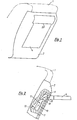
- - Fig. 1 die Rückenlehne eines Fahrgastsitzes mit verstauter Tischplatte,
- - Fig. 2 einen Ausschnitt der Rückenlehne nach Fig. 1, die Tischplatte jedoch in Gebrauchslage geschwenkt,
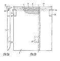
- - Fig. 3a,b eine Blende in Vorder- und Seitenansicht,
- - Fig. 3c eine Schnittdarstellung nach der Schnittlinie 111-111 in Fig. 3b,
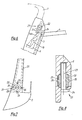
- - Fig. 4a,b eine Sperrklinke in Vorder- und Seitenansicht, in vergrössertem Massstab,
- - Fig. 5a,b eine Tischplatte in Vorder- und Seitenansicht,
- - Fig. 6 ein zweites Ausführungsbeispiel der Erfindung,
- - Fig. 7 eine Draufsicht nach Fig. 6 und
- - Fig. 8 eine Einzelheit nach Fig. 6, in vergrössertem Massstab.
- Eine Rückenlehne 1 einen nicht weiter dargestellten Fahrzeugsitzes eines Kraftfahrzeuges trägt eine formstabile Blende 2, die vorzugsweise aus Kunststoff hergestellt ist. Die Blende 2 weist eine Öffnung 3 (Fig. 3a) auf, in der eine Tischplatte 4 so eingesetzt ist, dass sie als Abdeckung der Öffnung 3 dient. Ferner ist die Blende 2 an der Rückenlehne festgeschraubt; die hierfür notwendigen Schraubenlöcher in der Blende sind aus den Fig. 3a und b erkennbar und dort mit 5 bezeichnet. Da die Tischplatte 4 oft als Schreib- und Leseunterlage verwendet wird, ist an der Blende 2 im oberen Bereich ihrer Öffnung 3 eine Leselampe 27 vorgesehen.
- Die Tischplatte 4 lässt sich durch Hochziehen und Umklappen in eine horizontale Gebrauchslage schwenken. Zu diesem Zweck weist sie an ihren Längsseiten je ein Führungselement 6a, 6b auf, mit denen sie in Längsnuten 7 in der Blende 2 geführt ist. Die Längsnuten 7 sind in der Blende 2 beidseitig der Öffnung 3 angebracht und erstrecken sich in vertikaler Richtung im wesentlichen über die ganze Länge der Öffnung 3. Die Führungselemente 6a, b werden gebildet von den überstehenden Enden eines formstabilen Stabes 6, der sich über die ganze Länge einer Durchgangsbohrung 8 in der Tischplatte 4 erstreckt. Die Durchgangsbohrung 8 verläuft mit Abstand parallel zur vorderen Kante 4a der Tischplatte 4.
- Als Vorderkante 4a ist die Kante bezeichnet, die bei umgeklappter Tischplatte 4 an der Rückenlehne 1 liegt.
- Die Längsnuten 7 gehen in ihrem oberen Teil jeweils in eine Tasche 9 über, jede Tasche 9 nimmt eine Sperrklinke 10 auf. Die Sperrklinken 10 (Fig. 4a, b) sind als Doppelarmhebel ausgelegt und mit ihrem Mittelabschnitt 11 drehbar in der Tasche 9 gelagert. Der erste Hebelarm weist an seinem Ende einen maulförmigen Einschnitt 12 auf. Am Ende des zweiten Hebelarms greift eine Feder 13 an, die die Sperrklinke 10 in vorgespannter Stellung in der Tasche 9 hält. In der Tasche 9 ist ein Vorsprung 14 ausgebildet. Er dient als Anschlag für die Sperrklinke 10, die hierfür eine Innenschulter 15 aufweist.
- Wird die Tischplatte 4 hochgezogen und umgeklappt, rasten ihre Führungselemente 6a, b in die maulförmigen Einschnitte 12 der Sperrklinken 10 ein. Die Tischplatte 4 ist dadurch festgelegt, sie kann nach unten nicht mehr wegrutschen. Darüber hinaus dienen die maulförmigen Einschnitte 12 als Lagerstellen für die drehbare Lagerung der Tischplatte 4 über die Führungselemente 6a, b.
- Um die Tischplatte 4 von ihrer Gebrauchslage in ihre Ruhelage verstauen zu können, müssen die Sperrklinken 10 gelöst werden. Die Sperrklinken 10 weisen hierfür am Ende ihres ersten Hebelarmes, oberhalb des maulförmigen Einschnittes 12 eine Lasche 16 auf, die so abgebogen ist, dass sie bei umgeklappter Tischplatte 4 auf deren Oberfläche liegt. Beim Verstauen wird die Tischplatte 4 zunächst nach oben geschwenkt. Dadurch werden die Sperrklinken 10 über die Laschen 16 nach hinten gedreht, bis sie die Führungselemente 6a, b freigeben.
- Sodann lässt sich die Tischplatte 4 in ihre Ruhelage absenken.
- Die Durchgangsbohrung 8 weist eine längliche Querschnittsform auf und ist mit dieser Querschnittsform in Längsrichtung der Tischplatte 4 ausgerichtet (Fig. 5a, b). Eine in der Durchgangsbohrung 8 angeordnete Blattfeder 17 drückt den formstabilen Stab 6 an die Wandung der Durchgangsbohrung 8, die von der vorderen Kante 4a der Tischplatte 4 entfernt liegt. Durch diese Anordnung ist der formstabile Stab 6 und seine als Führungselemente 6a, b dienenden Enden relativ zur Tischplatte in deren Längsrichtung verschiebbar gegen die Kraft der Blattfeder 17.
- An ihren Längsseiten und im Bereich der vorderen Kante 4a trägt die Tischplatte 4 je ein Zahnsegment 18, die mit einem U-förmigen Befestigungsabschnitt die Tischplatte 4 umgreifen und dort mit ihr befestigt sind. Die Befestigung kann mit Schrauben oder in sonstiger Weise vorgenommen werden. Ausserdem weisen die Zahnsegmente Durchbrüche auf für den Durchtritt der Führungselemente 6a, b. Die Zähne der Zahnsegmente 18 stehen über die vordere Kante 4a hinaus und greifen in die Zähne entsprechender Zahnsegmente 19 (Fig. 2), die in der Blende 2 festgelegt sind. Die Zahnsegmente 19 sind dabei in unmittelbarer Nachbarschaft der Sperrklinken 10 angeordnet.
- Will der Fahrgast die Tischplatte 4 in ihre Gebrauchslage schwenken, zieht er sie zunächst aus ihrer in Fig. 1 dargestellten Ruhelage an einer Griffmulde 20 nach oben und klappt sie dann, in dem er sie gleichzeitig zu sich herzieht, in die gewünschte Lage. Danach lässt er die Tischplatte los. Die Blattfeder 17 drückt sie nun nach vorn bis die Zahnsegmente 18, 19 ineinander greifen.
- Die Zahnform der Zahnsegmente 18, 19 ist dabei so gewählt, dass ein ungewolltes Weiterrasten vermieden wird bei einer Belastung der Tischplatte. Möchte der Fahrgast die Neigung der Tischplatte 4 verstellen, zieht er sie lediglich zu sich her, schwenkt sie in die gewünschte Lage und lässt sie wieder los:
- Beim Verstauen der Tischplatte 4 erfolgt die Handhabung umgekehrt. Der Fahrgast zieht die Tischplatte 4 zu sich her, klappt sie nach oben und lässt sie hinuntergleiten in ihre Ruhelage.
- In den Figuren 6-8 ist ein zweites Ausführungsbeispiel dargestellt. Hier sind in der Blende 2 oberhalb ihrer Öffnung 3 zwei Stellschrauben 21 angeordnet (in der Zeichnung ist aus Symmetriegründen nur eine Stellschraube dargestellt), an denen die umgeklappte Tischplatte mit ihren Ecken im Bereich der vorderen Kante anliegt. Die Stellschrauben 21 bestehen aus einer Mutter 22 und einem Gewindebolzen 23, der mit einer Auflagefläche 24 auf die Tischplatte 4 drückt. Die Mutter 22 ist in der Blende 2 drehbeweglich, ansonsten in ihrer Lage unverrückbar festgelegt. Der Gewindebolzen 23 lässt sich durch Drehen der Mutter 22 in axialer Richtung verstellen. In Fig. 7 - sie zeigt nur die Blende 2, ohne Tischplatte 4 und Rückenlehne 1 - ist ein Transmissionsband 25 erkennbar, das um die Muttern 22 geschlungen ist. Das Transmissionsband 25 dient zur gleichzeitigen Betätigung der beiden Muttern 22. Es ist für diesen Zweck als Lochband ausgeführt, in deren Löcher Zapfen 26 der Muttern 22 eingreifen. Die Zapfen 23 stehen in gleichmässigen Abständen am Umfang jeder Mutter 22 radial ab. Ihre Abstände zueinander entsprechen der Lochfolge des Transmissionsbandes 25.
- Will der Fahrgast die umgeklappte Tischplatte 4 in ihrer Neigung verstellen, bewegt er das Transmissionsband je nachdem nach links oder rechts. Dadurch drehen sich die Muttern 22 und die Gewindebolzen 23 verschieben sich axial. Da die Gewindebolzen 23 mit ihren Auflageflächen 24 auf die Tischplatte 4 wirken, schwenkt sie in die gewünschte Lage. Für die Betätigung des Transmissionsbandes 25 kann in der Blende 2 eine Öffnung vorgesehen sein, durch die das Band direkt mit der Hand bewegt werden kann. Zweckmässigeristaberein Stellorgan, das auf das Transmissionsband wirkt.
- Es ist ohne weiteres denkbar, dass die Tischplatte 4 ohne Blende direkt an der Rückenlehne angeordnet ist. In diesem Fall aber müsste die Rückenlehne entsprechend konstruktiv ausgestaltet sein.
Claims (13)
Applications Claiming Priority (2)
| Application Number | Priority Date | Filing Date | Title |
|---|---|---|---|
| DE3130566 | 1981-08-01 | ||
| DE3130566 | 1981-08-01 |
Publications (2)
| Publication Number | Publication Date |
|---|---|
| EP0071817A1 EP0071817A1 (de) | 1983-02-16 |
| EP0071817B1 true EP0071817B1 (de) | 1985-09-25 |
Family
ID=6138400
Family Applications (1)
| Application Number | Title | Priority Date | Filing Date |
|---|---|---|---|
| EP82106526A Expired EP0071817B1 (de) | 1981-08-01 | 1982-07-20 | Einrichtung zur schwenkbaren Anordnung einer Tischplatte an der Rückenlehne eines Fahrgastsitzes |
Country Status (4)
| Country | Link |
|---|---|
| US (1) | US4519648A (de) |
| EP (1) | EP0071817B1 (de) |
| DE (1) | DE3266555D1 (de) |
| ZA (1) | ZA825126B (de) |
Families Citing this family (28)
| Publication number | Priority date | Publication date | Assignee | Title |
|---|---|---|---|---|
| DE3421547C1 (de) * | 1984-06-08 | 1985-09-05 | Bayerische Motoren Werke AG, 8000 München | Kraftfahrzeugsitz mit einer an seiner Rückenlehne schwenkbar gelagerten Tischplatte |
| DE4125783A1 (de) * | 1991-08-03 | 1993-02-04 | Askon Aldenhoff & Schnell Kons | Tischanordnung zur montage an einem fahrzeugteil |
| DE4126427C1 (de) * | 1991-08-09 | 1992-11-26 | Mercedes-Benz Aktiengesellschaft, 7000 Stuttgart, De | |
| US5267775A (en) * | 1991-10-03 | 1993-12-07 | B/E Avionics, Inc. | System for mounting a monitor |
| US5863092A (en) * | 1996-06-24 | 1999-01-26 | Chrysler Corporation | Bucket seat mounted apparatus for hanging articles |
| FR2770183B1 (fr) * | 1997-10-24 | 2001-04-06 | Magaplast Sa | Tablette rabattable, applicable a des sieges de vehicules |
| FR2775639B1 (fr) * | 1998-03-05 | 2000-03-31 | Peugeot | Mecanisme d'articulation pour tablette rabattable, notamment pour vehicule automobile |
| JP3991461B2 (ja) * | 1998-08-11 | 2007-10-17 | 日産自動車株式会社 | テーブル装置 |
| US6994401B1 (en) * | 2000-09-14 | 2006-02-07 | Lear Corporation | Seat backrest cover module |
| US6761398B2 (en) | 2001-05-25 | 2004-07-13 | Weber Aircraft Lp | Stowable tables |
| FR2829976B1 (fr) * | 2001-09-26 | 2004-01-09 | Peugeot Citroen Automobiles Sa | Dispositif a tablette rabattable pour vehicule automobile et siege comportant un tel dispositif |
| FR2831496B1 (fr) * | 2001-10-26 | 2005-01-07 | Peugeot Citroen Automobiles Sa | Siege pour vehicule automobile avec tablette articulee |
| US6619733B2 (en) | 2001-11-19 | 2003-09-16 | The Boeing Company | Passenger seat headrest platform |
| US20080208694A1 (en) * | 2003-08-08 | 2008-08-28 | Baggott David I | Concession tray |
| US7341005B2 (en) * | 2003-08-08 | 2008-03-11 | Baggott David I | Concession tray |
| KR100770985B1 (ko) * | 2003-08-20 | 2007-10-30 | 삼성전자주식회사 | 디스플레이 장치 |
| US20050205507A1 (en) * | 2004-03-19 | 2005-09-22 | Heidel Lena L | Garment drying rack |
| FR2877289B1 (fr) * | 2004-11-04 | 2006-12-22 | Renault Sas | Table modulable de vehicule automobile |
| FR2883529B1 (fr) * | 2005-03-25 | 2008-02-15 | Faurecia Sieges Automobile | Siege de vehicule a tablette reglable et adaptable |
| JP4906082B2 (ja) * | 2006-09-11 | 2012-03-28 | 株式会社リコー | 角度調整装置及び画像形成装置 |
| KR100962145B1 (ko) * | 2008-11-28 | 2010-06-10 | 현대자동차주식회사 | 시트백 테이블 로킹장치 |
| US20110109114A1 (en) * | 2009-11-09 | 2011-05-12 | Gm Global Technology Operations, Inc. | Seat for a vehicle |
| GB2488801A (en) * | 2011-03-09 | 2012-09-12 | William Gniadek | Utility tray for use with motor vehicle |
| DE102012004342B4 (de) * | 2012-03-07 | 2014-09-18 | Johnson Controls Gmbh | Ausstattungsteil für einen Fahrzeugsitz und Fahrzeugsitz |
| DE102012012850B4 (de) * | 2012-06-26 | 2015-01-08 | Johnson Controls Gmbh | Fahrzeugsitz |
| KR101704267B1 (ko) * | 2015-10-06 | 2017-02-08 | 현대자동차주식회사 | 워머가 구비된 시트 |
| US11401037B2 (en) * | 2018-11-01 | 2022-08-02 | Safran Seats Usa Llc | Seat having an auxiliary tablet |
| US12030415B2 (en) * | 2019-07-31 | 2024-07-09 | Safran Seats Usa Llc | Vertically adjustable tray table |
Family Cites Families (10)
| Publication number | Priority date | Publication date | Assignee | Title |
|---|---|---|---|---|
| GB515558A (en) * | 1938-06-22 | 1939-12-07 | Brexton Ltd | Improved occasional table |
| US2383125A (en) * | 1942-05-13 | 1945-08-21 | Hill Joanna | Railroad seat |
| US2619395A (en) * | 1949-05-09 | 1952-11-25 | Thomas A Kent | Adjustable folding table for automobile seats |
| DE898860C (de) * | 1951-07-05 | 1953-12-03 | Daimler Benz Ag | Personenkraftwagen mit Einrichtungen zum Anbringen eines Tisches |
| US2653036A (en) * | 1951-08-01 | 1953-09-22 | James E Creel | Swingable vehicle step |
| FR1209207A (fr) * | 1958-07-25 | 1960-02-29 | & Commerciale R Marechal Soc I | Siège notamment pour véhicules |
| US2963078A (en) * | 1959-11-19 | 1960-12-06 | Charles H Ferrelle | Folding table for motor vehicles |
| DE1909998A1 (de) * | 1968-02-29 | 1969-09-18 | Hardman Aerospace | Klapptisch fuer einen Fahrzeugsitz,insbesondere einen Flugzeugsitz |
| US3550891A (en) * | 1968-12-04 | 1970-12-29 | Charles F Scott | Adjustable shelf bracket |
| JPS55164533A (en) * | 1979-06-12 | 1980-12-22 | Nhk Spring Co Ltd | Seat for automobile |
-
1982
- 1982-07-19 ZA ZA825126A patent/ZA825126B/xx unknown
- 1982-07-20 DE DE8282106526T patent/DE3266555D1/de not_active Expired
- 1982-07-20 EP EP82106526A patent/EP0071817B1/de not_active Expired
- 1982-07-21 US US06/400,256 patent/US4519648A/en not_active Expired - Fee Related
Also Published As
| Publication number | Publication date |
|---|---|
| DE3266555D1 (en) | 1985-10-31 |
| ZA825126B (en) | 1983-05-25 |
| US4519648A (en) | 1985-05-28 |
| EP0071817A1 (de) | 1983-02-16 |
Similar Documents
| Publication | Publication Date | Title |
|---|---|---|
| EP0071817B1 (de) | Einrichtung zur schwenkbaren Anordnung einer Tischplatte an der Rückenlehne eines Fahrgastsitzes | |
| DE2326223C3 (de) | Gelenkbeschlag für Sitze mit verstellbarer Lehne, insbesondere Kraftfahrzeugsitze | |
| DE2941303C2 (de) | Vorrichtung zum Einstellen des Neigungswinkels der Lenksäule einer Kraftfahrzeuglenkung | |
| DE7927079U1 (de) | Sitz mit einer am sitzrahmen angelenkten, neigungsverstellbaren rueckenlehne | |
| DE69811782T2 (de) | Neigungsverstellmechanismus für Fahrzeugsitz | |
| DE2927377A1 (de) | Sitzmoebel, insbesondere buerodrehstuhl | |
| DE69526015T2 (de) | Verriegelungsmechanismus zur Ausrüstung einer Landmaschine | |
| CH642423A5 (de) | Traggelenk fuer gelenkarme an markisen. | |
| DE2910448C2 (de) | ||
| DE10142081A1 (de) | Stuhl | |
| DE2721539A1 (de) | Fahrzeugsitz | |
| DE3223528A1 (de) | Einrichtung zur schwenkbaren anordnung einer tischplatte an der rueckenlehne eines fahrgastsitzes | |
| DE1555490B1 (de) | Einstellbare Lenksaeule fuer Kraftfahrzeuge | |
| DE2045359C3 (de) | Neigungsverstellbarer Fahrzeugsitz | |
| DE69408206T2 (de) | Gelenkbeschlag für Fahrzeugsitz | |
| DE4102312C2 (de) | Sitzschiene für Fahrzeugsitze, insbesondere für Kraftfahrzeugsitze | |
| DE2206884B2 (de) | Höhen- und Neigungsverstelleinrichtung für Fahrzeugsitze | |
| DE4419407C2 (de) | Armlehne für Fahrzeugsitze | |
| DE2265374C2 (de) | Höhen- und Neigungsverstelleinrichtung für Fahrzeugsitze | |
| DE2018766A1 (de) | Gelenkbeschlag, insbesondere für Fahrzeugsitze | |
| DE9005572U1 (de) | Wagenheber | |
| DE19649339B4 (de) | Außenrückblickspiegel für Fahrzeuge, vorzugsweise für Kraftfahrzeuge | |
| DE4113538A1 (de) | Verstellbare haltevorrichtung fuer die sitzrueckenlehne eines kinderwagens | |
| DE2919715C2 (de) | Beinstütze | |
| DE2731332C2 (de) | Schwenkvorrichtung für Fahrzeugscheinwerfer |
Legal Events
| Date | Code | Title | Description |
|---|---|---|---|
| PUAI | Public reference made under article 153(3) epc to a published international application that has entered the european phase |
Free format text: ORIGINAL CODE: 0009012 |
|
| AK | Designated contracting states |
Designated state(s): DE FR GB IT SE |
|
| 17P | Request for examination filed |
Effective date: 19830111 |
|
| ITF | It: translation for a ep patent filed | ||
| GRAA | (expected) grant |
Free format text: ORIGINAL CODE: 0009210 |
|
| AK | Designated contracting states |
Designated state(s): DE FR GB IT SE |
|
| REF | Corresponds to: |
Ref document number: 3266555 Country of ref document: DE Date of ref document: 19851031 |
|
| ET | Fr: translation filed | ||
| PLBE | No opposition filed within time limit |
Free format text: ORIGINAL CODE: 0009261 |
|
| STAA | Information on the status of an ep patent application or granted ep patent |
Free format text: STATUS: NO OPPOSITION FILED WITHIN TIME LIMIT |
|
| 26N | No opposition filed | ||
| REG | Reference to a national code |
Ref country code: GB Ref legal event code: 746 |
|
| REG | Reference to a national code |
Ref country code: FR Ref legal event code: DL |
|
| PGFP | Annual fee paid to national office [announced via postgrant information from national office to epo] |
Ref country code: SE Payment date: 19910704 Year of fee payment: 10 |
|
| PGFP | Annual fee paid to national office [announced via postgrant information from national office to epo] |
Ref country code: DE Payment date: 19910712 Year of fee payment: 10 |
|
| PGFP | Annual fee paid to national office [announced via postgrant information from national office to epo] |
Ref country code: GB Payment date: 19910719 Year of fee payment: 10 |
|
| PGFP | Annual fee paid to national office [announced via postgrant information from national office to epo] |
Ref country code: FR Payment date: 19910730 Year of fee payment: 10 |
|
| ITTA | It: last paid annual fee | ||
| PG25 | Lapsed in a contracting state [announced via postgrant information from national office to epo] |
Ref country code: GB Effective date: 19920720 |
|
| PG25 | Lapsed in a contracting state [announced via postgrant information from national office to epo] |
Ref country code: SE Effective date: 19920721 |
|
| GBPC | Gb: european patent ceased through non-payment of renewal fee |
Effective date: 19920720 |
|
| PG25 | Lapsed in a contracting state [announced via postgrant information from national office to epo] |
Ref country code: FR Effective date: 19930331 |
|
| PG25 | Lapsed in a contracting state [announced via postgrant information from national office to epo] |
Ref country code: DE Effective date: 19930401 |
|
| REG | Reference to a national code |
Ref country code: FR Ref legal event code: ST |
|
| EUG | Se: european patent has lapsed |
Ref document number: 82106526.5 Effective date: 19930204 |