EP0071868A2 - Tour frontal - Google Patents
Tour frontal Download PDFInfo
- Publication number
- EP0071868A2 EP0071868A2 EP82106757A EP82106757A EP0071868A2 EP 0071868 A2 EP0071868 A2 EP 0071868A2 EP 82106757 A EP82106757 A EP 82106757A EP 82106757 A EP82106757 A EP 82106757A EP 0071868 A2 EP0071868 A2 EP 0071868A2
- Authority
- EP
- European Patent Office
- Prior art keywords
- tailstock
- lathe
- headstock
- bracket
- spindle
- Prior art date
- Legal status (The legal status is an assumption and is not a legal conclusion. Google has not performed a legal analysis and makes no representation as to the accuracy of the status listed.)
- Withdrawn
Links
Images
Classifications
-
- B—PERFORMING OPERATIONS; TRANSPORTING
- B23—MACHINE TOOLS; METAL-WORKING NOT OTHERWISE PROVIDED FOR
- B23B—TURNING; BORING
- B23B3/00—General-purpose turning-machines or devices, e.g. centre lathes with feed rod and lead screw; Sets of turning-machines
- B23B3/06—Turning-machines or devices characterised only by the special arrangement of constructional units
Definitions
- the invention relates to a lathe with a headstock and a tailstock.
- the tailstock is slidably and lockably arranged on a bed, the guideways of which run axially parallel to the spindle of the lathe.
- This bed has a certain length, which is so great that the machine is no longer accessible from the front.
- the object of the invention is to provide a tailstock arrangement which allows access from the front to the spindle of the lathe or to the chuck of the spindle.
- This configuration ensures that the long bed guide previously required for the tailstock is eliminated, so that accessibility from the front is made possible.
- This not only makes loading the machine easier by hand, it also enables connection to an automatic loading device, e.g. B. a loading portal, an automatic workpiece handling in a simple manner.
- This automatic workpiece handling is particularly simplified if, in a further embodiment of the invention, the console is guided displaceably on the headstock. In this way, accessibility from both sides is possible over a very large area, which is restricted only by the console, which can be kept relatively narrow.
- all tailstocks assigned to the spindles can be arranged on a common console.
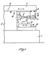
- a headstock 2 On a machine frame 1, a headstock 2 is arranged, the spindle 3 carries a chuck 4, in which a workpiece 5 is clamped, which projects so far out of the chuck 4 that it must be supported at its free end by a tailstock.
- a tailstock 6 is fixed to a bracket 7 by means of clamping screws 8.
- the console 7 is slidably guided on a guide 9 on the headstock 2, for which purpose an adjusting spindle 10 is provided.
- the tailstock 6 carries a quill 11 which can be actuated hydraulically and, for this purpose, has a piston 12 which can be acted on from both sides and which can be acted upon via corresponding supply and discharge lines (not shown) such that the quill 11 with its tip 13 is against the workpiece 5 Support the same driven and can be withdrawn after the final processing of the same.
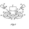
- a tool holder 15 is provided on a slide 14 which can be displaced transversely to the axis of the spindle 3 in order to be able to machine the workpiece 5.
- two such slides 14 are provided with two tool holders 15, each of which carries a tool 16 for simultaneous machining of the workpiece.
Landscapes
- Engineering & Computer Science (AREA)
- Mechanical Engineering (AREA)
- Turning (AREA)
Applications Claiming Priority (2)
| Application Number | Priority Date | Filing Date | Title |
|---|---|---|---|
| DE3130701 | 1981-08-03 | ||
| DE19813130701 DE3130701A1 (de) | 1981-08-03 | 1981-08-03 | Frontdrehmaschine |
Publications (2)
| Publication Number | Publication Date |
|---|---|
| EP0071868A2 true EP0071868A2 (fr) | 1983-02-16 |
| EP0071868A3 EP0071868A3 (fr) | 1984-02-08 |
Family
ID=6138487
Family Applications (1)
| Application Number | Title | Priority Date | Filing Date |
|---|---|---|---|
| EP82106757A Withdrawn EP0071868A3 (fr) | 1981-08-03 | 1982-07-27 | Tour frontal |
Country Status (4)
| Country | Link |
|---|---|
| EP (1) | EP0071868A3 (fr) |
| JP (1) | JPS5828401A (fr) |
| DE (1) | DE3130701A1 (fr) |
| ES (1) | ES266765Y (fr) |
Families Citing this family (1)
| Publication number | Priority date | Publication date | Assignee | Title |
|---|---|---|---|---|
| DE19651474C2 (de) * | 1995-12-20 | 2000-05-18 | Ilg Gmbh | Werkzeugmaschine |
Family Cites Families (6)
| Publication number | Priority date | Publication date | Assignee | Title |
|---|---|---|---|---|
| US1845478A (en) * | 1929-08-03 | 1932-02-16 | Bullard Co | Automatic multiple spindle center turning machine |
| DE649097C (de) * | 1935-08-08 | 1937-08-16 | Franz Emil Oskar Hoppe | Drehbank mit Starr-Rahmen |
| FR1095496A (fr) * | 1953-12-07 | 1955-06-03 | Tour vertical | |
| FR1195400A (fr) * | 1958-04-24 | 1959-11-17 | Dispositif électrique de sécurité pour exécution de travaux entre pointes sur machines-outils | |
| DE1263453B (de) * | 1958-08-12 | 1968-03-14 | Menziken Ag Maschf | Senkrecht-Drehmaschine |
| GB1459187A (en) * | 1973-01-10 | 1976-12-22 | Centrax Ltd | Machine tools |
-
1981
- 1981-08-03 DE DE19813130701 patent/DE3130701A1/de not_active Withdrawn
-
1982
- 1982-07-27 EP EP82106757A patent/EP0071868A3/fr not_active Withdrawn
- 1982-07-30 JP JP13232782A patent/JPS5828401A/ja active Pending
- 1982-08-02 ES ES1982266765U patent/ES266765Y/es not_active Expired
Also Published As
| Publication number | Publication date |
|---|---|
| JPS5828401A (ja) | 1983-02-19 |
| ES266765U (es) | 1983-02-16 |
| EP0071868A3 (fr) | 1984-02-08 |
| ES266765Y (es) | 1983-08-16 |
| DE3130701A1 (de) | 1983-02-10 |
Similar Documents
| Publication | Publication Date | Title |
|---|---|---|
| DE68922189T2 (de) | Drehautomat mit verschiebbarem Spindelstock und Bearbeitungsverfahren zum Anwenden desselben. | |
| EP0334298B1 (fr) | Méthode et dispositif d'usinage de pièces à symétrie rotative | |
| DE2739534C2 (de) | Werkzeugwechselvorrichtung | |
| DE3035451C3 (de) | Drehmaschine mit zwei sich axial gegenüberliegenden Werkstückspindeln | |
| EP0123956B1 (fr) | Rectifieuse cylindrique pour rectification intérieure et extérieure avec commande numérique | |
| DE3320940C2 (fr) | ||
| EP3784432B1 (fr) | Machine-outil avec une broche de travail montee sur une surface inclinee | |
| DE2033026B2 (de) | NC-gesteueites Bearbeitungszentrum für durch Drehen von beiden Seiten her sowie durch Fräsen und/oder Bohren zu bearbeitende Werkstücke | |
| EP1413395A1 (fr) | Machine-outil | |
| EP0260692B1 (fr) | Machine-outil avec un porte-broche à forer et à fraiser à déplacement dans la direction Z sur un châssis de machine | |
| EP0064766A2 (fr) | Méthode et dispositif pour le travail de pièces ayant une symétrie de rotation | |
| DE69102511T2 (de) | Werkzeugmaschine, insbesondere für dekolletieren. | |
| EP0573678A1 (fr) | Tour multibroche | |
| DE936176C (de) | Selbsttaetige Drehbank | |
| DE20104030U1 (de) | Bearbeitungsmaschine, insbesondere zum Schleifen von Werkzeugen | |
| DE19844243A1 (de) | Universalschleifmaschine | |
| DE60007777T2 (de) | Bearbeitungsanlage mit rundschleifstationen | |
| DE10111098A1 (de) | Bearbeitungsmaschine, insbesondere zum Schleifen von Werkzeugen | |
| DE3028685A1 (de) | Einrichtung zum bearbeiten von werkstuecken, wie bohren, fraesen o.a., insbesondere in form eines mehrspindeligen bearbeitungszentrum | |
| DE3826985C1 (fr) | ||
| DE3901888A1 (de) | Werkzeugbestueckte drehraeummaschine | |
| EP0239714A1 (fr) | Machine pour l'usinage des extrémités de pièces | |
| EP0071868A2 (fr) | Tour frontal | |
| DE202006016020U1 (de) | 2-fach nutzbare Werkbank | |
| DE19860867B4 (de) | Werkzeugmaschine mit automatischem Werkzeugwechsel |
Legal Events
| Date | Code | Title | Description |
|---|---|---|---|
| PUAI | Public reference made under article 153(3) epc to a published international application that has entered the european phase |
Free format text: ORIGINAL CODE: 0009012 |
|
| 17P | Request for examination filed |
Effective date: 19821123 |
|
| AK | Designated contracting states |
Designated state(s): AT CH DE FR GB IT LI |
|
| PUAL | Search report despatched |
Free format text: ORIGINAL CODE: 0009013 |
|
| AK | Designated contracting states |
Designated state(s): AT CH DE FR GB IT LI |
|
| STAA | Information on the status of an ep patent application or granted ep patent |
Free format text: STATUS: THE APPLICATION HAS BEEN WITHDRAWN |
|
| 18W | Application withdrawn |
Withdrawal date: 19840723 |
|
| RIN1 | Information on inventor provided before grant (corrected) |
Inventor name: HESSBRUEGGEN, NORBERT |