EP0071910A2 - Zündsystem für Brennkraft Maschine - Google Patents
Zündsystem für Brennkraft Maschine Download PDFInfo
- Publication number
- EP0071910A2 EP0071910A2 EP82106912A EP82106912A EP0071910A2 EP 0071910 A2 EP0071910 A2 EP 0071910A2 EP 82106912 A EP82106912 A EP 82106912A EP 82106912 A EP82106912 A EP 82106912A EP 0071910 A2 EP0071910 A2 EP 0071910A2
- Authority
- EP
- European Patent Office
- Prior art keywords
- ignition
- voltage
- engine
- signal
- low
- Prior art date
- Legal status (The legal status is an assumption and is not a legal conclusion. Google has not performed a legal analysis and makes no representation as to the accuracy of the status listed.)
- Withdrawn
Links
- 238000002485 combustion reaction Methods 0.000 title claims abstract description 14
- 238000004804 winding Methods 0.000 claims abstract description 51
- 230000004044 response Effects 0.000 claims description 7
- 239000000446 fuel Substances 0.000 abstract description 6
- 230000005540 biological transmission Effects 0.000 abstract description 3
- 230000000875 corresponding effect Effects 0.000 abstract 1
- 239000000203 mixture Substances 0.000 abstract 1
- 239000003990 capacitor Substances 0.000 description 8
- 238000010586 diagram Methods 0.000 description 4
- 238000010276 construction Methods 0.000 description 3
- 230000015654 memory Effects 0.000 description 3
- 230000006835 compression Effects 0.000 description 2
- 238000007906 compression Methods 0.000 description 2
- 239000000498 cooling water Substances 0.000 description 2
- 230000003247 decreasing effect Effects 0.000 description 2
- 230000000712 assembly Effects 0.000 description 1
- 238000000429 assembly Methods 0.000 description 1
- 238000006243 chemical reaction Methods 0.000 description 1
- 230000000694 effects Effects 0.000 description 1
- 230000008030 elimination Effects 0.000 description 1
- 238000003379 elimination reaction Methods 0.000 description 1
- 238000010304 firing Methods 0.000 description 1
- 230000006870 function Effects 0.000 description 1
- 238000000034 method Methods 0.000 description 1
- 238000012986 modification Methods 0.000 description 1
- 230000004048 modification Effects 0.000 description 1
Images




Classifications
-
- F—MECHANICAL ENGINEERING; LIGHTING; HEATING; WEAPONS; BLASTING
- F02—COMBUSTION ENGINES; HOT-GAS OR COMBUSTION-PRODUCT ENGINE PLANTS
- F02P—IGNITION, OTHER THAN COMPRESSION IGNITION, FOR INTERNAL-COMBUSTION ENGINES; TESTING OF IGNITION TIMING IN COMPRESSION-IGNITION ENGINES
- F02P7/00—Arrangements of distributors, circuit-makers or -breakers, e.g. of distributor and circuit-breaker combinations or pick-up devices
- F02P7/02—Arrangements of distributors, circuit-makers or -breakers, e.g. of distributor and circuit-breaker combinations or pick-up devices of distributors
- F02P7/03—Arrangements of distributors, circuit-makers or -breakers, e.g. of distributor and circuit-breaker combinations or pick-up devices of distributors with electrical means
- F02P7/035—Arrangements of distributors, circuit-makers or -breakers, e.g. of distributor and circuit-breaker combinations or pick-up devices of distributors with electrical means without mechanical switching means
-
- F—MECHANICAL ENGINEERING; LIGHTING; HEATING; WEAPONS; BLASTING
- F02—COMBUSTION ENGINES; HOT-GAS OR COMBUSTION-PRODUCT ENGINE PLANTS
- F02P—IGNITION, OTHER THAN COMPRESSION IGNITION, FOR INTERNAL-COMBUSTION ENGINES; TESTING OF IGNITION TIMING IN COMPRESSION-IGNITION ENGINES
- F02P15/00—Electric spark ignition having characteristics not provided for in, or of interest apart from, groups F02P1/00 - F02P13/00 and combined with layout of ignition circuits
- F02P15/12—Electric spark ignition having characteristics not provided for in, or of interest apart from, groups F02P1/00 - F02P13/00 and combined with layout of ignition circuits having means for strengthening spark during starting
-
- F—MECHANICAL ENGINEERING; LIGHTING; HEATING; WEAPONS; BLASTING
- F02—COMBUSTION ENGINES; HOT-GAS OR COMBUSTION-PRODUCT ENGINE PLANTS
- F02P—IGNITION, OTHER THAN COMPRESSION IGNITION, FOR INTERNAL-COMBUSTION ENGINES; TESTING OF IGNITION TIMING IN COMPRESSION-IGNITION ENGINES
- F02P3/00—Other installations
- F02P3/02—Other installations having inductive energy storage, e.g. arrangements of induction coils
- F02P3/04—Layout of circuits
- F02P3/045—Layout of circuits for control of the dwell or anti dwell time
- F02P3/0453—Opening or closing the primary coil circuit with semiconductor devices
- F02P3/0456—Opening or closing the primary coil circuit with semiconductor devices using digital techniques
-
- F—MECHANICAL ENGINEERING; LIGHTING; HEATING; WEAPONS; BLASTING
- F02—COMBUSTION ENGINES; HOT-GAS OR COMBUSTION-PRODUCT ENGINE PLANTS
- F02P—IGNITION, OTHER THAN COMPRESSION IGNITION, FOR INTERNAL-COMBUSTION ENGINES; TESTING OF IGNITION TIMING IN COMPRESSION-IGNITION ENGINES
- F02P3/00—Other installations
- F02P3/02—Other installations having inductive energy storage, e.g. arrangements of induction coils
- F02P3/04—Layout of circuits
- F02P3/05—Layout of circuits for control of the magnitude of the current in the ignition coil
- F02P3/051—Opening or closing the primary coil circuit with semiconductor devices
-
- F—MECHANICAL ENGINEERING; LIGHTING; HEATING; WEAPONS; BLASTING
- F02—COMBUSTION ENGINES; HOT-GAS OR COMBUSTION-PRODUCT ENGINE PLANTS
- F02P—IGNITION, OTHER THAN COMPRESSION IGNITION, FOR INTERNAL-COMBUSTION ENGINES; TESTING OF IGNITION TIMING IN COMPRESSION-IGNITION ENGINES
- F02P9/00—Electric spark ignition control, not otherwise provided for
- F02P9/002—Control of spark intensity, intensifying, lengthening, suppression
- F02P9/007—Control of spark intensity, intensifying, lengthening, suppression by supplementary electrical discharge in the pre-ionised electrode interspace of the sparking plug, e.g. plasma jet ignition
Definitions
- the present invention relates generally to an ignition system for an internal combustion engine, and more specifically to an ignition system for an internal combustion engine, wherein ignition coil and spark plug are integrally incorporated into each engine cylinder to eliminate ignition energy loss caused by conventional high-tension cables and a DC-DC converter for boosting DC voltage is connected to each secondary winding of the ignition coil so as to operatively apply the high DC voltage across each spark plug so as to extend the discharge duration of each spark plug under such an engine operating condition as a low engine speed (engine start, idling speed, etc.) and light engine load condition.
- a conventional ignition system for an internal combustion engine includes:
- the primary winding of the ignition coil provides an alternating current flow so that the secondary winding thereof produces a multiplied high AC voltage.
- the AC voltage generates the spark discharge twice within one .engine cycle at each spark plug, i.e., first in the compression stroke and second in the exhaust stroke.
- the ignition system described hereinabove is a "Haltig" ignition system. In such ignition system, there is an advantage that the efficiency of ignition energy is enhanced with the elimination of transmission energy loss, since there is no conventional mechanical distributor and central cord associated with the distributor.
- the conventional ignition system ignites twice within each engine cycle for each engine cylinder, there is no effect of eliminating the mechanical distributor and a large power consumption of the vehicle battery as the low DC bias supply and wasteful fuel consumption accordingly result.
- the weight of the ignition coil is increased so that more wider space is required.
- an object of the present invention to provide an ignition system for a multi-cylinder internal combustion engine, wherein a cylinder judging circuit provided at a primary winding of an ignition coil discriminates one of the spark plugs to be ignited according to a predetermined ignition order in response to a pulse signal representative of an engine cycle so that one ignition is carried out within each engine cycle for one of the engine cylinders, wherein the ignition coil is integrally assembled with the corresponding spark plug into each engine cylinder for eliminating the wasteful consumption of ignition energy due to a high-tension cable conventionally provided between the ignition coil and corresponding spark plug, and wherein the ignition energy is varied according to engine operating condition by changing the output timing of the ignition pulse signal to be fed into the cylinder judging circuit and by applying a high DC voltage across the secondary winding and corresponding spark plug.
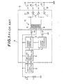
- First Fig. 1 shows a conventional "Haltig" ignition system used for a four-cylinder internal combustion engine.
- numeral 1 denotes a low DC voltage bias supply such as a vehicle battery.
- Numeral 2 denotes an ignition switch.
- Numeral 3 denotes an ignition signal detector, e.g., crank angle detector which produces a first pulse signal, i.e., 720° signal whenever the engine revolves two revolutions, i.e., the engine revolves one engine cycle. It should be noted that the ignition signal detector 3 produces a second pulse signal whenever the engine revolves through an angle predetermined by the number of engine cylinders, e.g., 180° in the case of .tour-cyllnder engine.
- Numeral 4 denotes an ignitor. The internal construction of the ignitor 4 is described hereinafter.
- Numeral 9 denotes an ignition coil section having an ignition coil 10 and plurality of diodes 11. Both ends 8 of a primary winding of the ignition coil 10 are connected to the ignitor 4. Both ends of a secondary winding of the ignition coil 10 are connected to a plurality of spark plugs 13 within the engine cylinders via the diodes 11 having high reverse voltage withstanding characteristics so as to form a current circuit of a couple of the spark plugs 13. One electrode of each spark plug 13 is bundled and grounded and the other electrode of two spark plugs 13 is connected to either end of the secondary winding of the ignition coil 10. The connection between the secondary winding of the ignition coil 10 and each diode 11 is made with a high-tension cable.
- the ignitor 4 comprises: (a) an ignition advance angle controller 5 which controls the actual ignition timing of the spark plugs 13 on a basis of the piston stroke position of each engine cylinder related to a top dead center; (b) a pair of primary winding current flow-angle controllers 6, each connected to the ignition advance angle controller 5 for controlling the current flow through the primary winding of the ignition coil 10 and limiting the peak value of the primary current; and (c) a .pair of power transistors 7, each collector being connected to the corresponding end of the primary winding of the ignition coil 10, each emitter being grounded, and each base being connected to the corresponding primary current controller 6 so that the conduct interval of time of both power transistors 7 is controlled by the pair of primary current flow-angle controllers 6.
- a current that flows in opposite directions is produced at the primary winding of the ignition coil 10 with the intermediate tap as a center whenever the pair of power transistors 7 are alternatingly turned on. Furthermore, the spark plug 13 within each engine cylinder sparks twice at an interval of one engine cycle, i.e., at both compression and exhaust strokes.
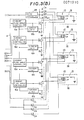
- Figs. 2(A) and 2(B) show in combination a first preferred embodiment of the present invention, particularly applied to the four-cylinder engine.
- the ignition coil 10 is of a closed magnetic circuit type having a high energy conversion efficiency and is built in an insulating housing 16 together with the corresponding spark plug 13 to assemble a pair of the ignition coil 10 and spark plug 13 so as to attach to each engine cylinder.
- each central electrode of the spark plugs 13 is connected to one end of the corresponding secondary winding L 2 with corresponding side electrode thereof being grounded.
- the 'other end of each secondary winding L 2 thereof is connected to an output terminal HD of an DC-DC converter 17 via one of diodes D 1 through D 4 .
- the DC-DC converter 17 is provided for boosting a low DC voltage e.g., 12 volts into a high DC voltage, e.g., in a range from 1000 upto 2000 volts.
- the high DC voltage is operatively applied across the respective spark plugs 13 via the corresponding secondary windings L 2 of the ignition coils 10 (in this embodiment, a negatively high DC voltage having an absolute value in the range described above is applied across each ignition coil 13 and secondary winding L 2 via the corresponding diode D i through D 4 as seen from Figs. 2(A) and 2(B)) for maintaining a continuous discharge within the respective spark plugs 13 in response to the interruption of the primary current to be described hereinbelow.
- an on/off controller 18 is provided at the front stage of the DC-DC converter 17 which turns on in response to an output signal from an ignition advance angle control unit 5 to be described hereinbelow so as to actuate the DC-DC converter 17 depending on a particular engine operating condition.
- the ignition advance angle control unit 5 comprises: (a) a counter 19; (b) comparator 20; (c) register 21; (d) memories 22 and 23; ⁇ and (e) arithmetic operation circuit 24.
- the ignition signal detector 3 produces a third pulse signal whose pulsewidth corresponds to 1° (one degree) of revolutional angle of the engine (engine -crankshaft), second pulse signal whose period corresponds to 180° of revolutional .angle of the engine (engine crankshaft), and first pulse signal whose period corresponds to 720° (two revolutions) of revolutional angle of the engine (engine crankshaft).
- the ignition advance angle control unit 5 receives the third and second pulse signals in such a way that the arithmetic operation circuit 24 and counter 19 receive the second pulse signal as a reset signal.
- the arithmetic operation circuit 24 accepts output signals from a knocking sensor 25 indicating the presence of the engine knocking, engine load sensor 26 indicating engine load e.g., from an fuel intake quantity, and engine speed sensor 27 indicating the current engine speed and reads stored data within the memories 22 and 23 so as to perform the calculation of ignition advance angle with respect to a top dead center (TDC) of each piston.
- the calculated result is temporarily stored in the register 21.
- the comparator 20 outputs the ignition pulse signal into a cylinder judging circuit 14 comprising, e.g., a four-bit ring counter (the bit number corresponds to the number of engine cylinders).
- the cylinder judging circuit 14 designates the engine cylinder which is a turn of the ignition in response to the first 720° pulse signal from the ignition signal detector 3 so as to circularly distribute an ignition start signal having each pulsewidth corresponding to 180° revolutional angle based on the ignition pulse signal from the comparator 20 into the designated engine cylinder via a primary current flow-angle controller 6a and corresponding power transistors 7.
- the ignition start signal is outputted at a timing when the ignition pulse signal is received from the comparator 20 into the current flow-angle controller 6a and current limiting circuit 6b.
- the corresponding power transistor 7 then changes its conductivity so that the primary current of the corresponding ignition coil 10 is controlled and counter electromotive force is generated and a high surge voltage is generated at a secondary winding L 2 of the corresponding ignition coil 10.
- the function of the current flow-angle controllers 6a and current limiters 6b correspond to the primary current controller 6 shown in Fig. 1.
- the arithmetic operation circuit 24 outputs a start command signal into the on/off control circuit 18 to enable the current flow from the low DC voltage supply (battery) 1 to the DC-DC converter 17 so that the DC-DC converter 17 is actuated to produce the high DC voltage.
- the on/off control circuit 18 comprise> e.g., an analog switch.
- the start command signal is outputted when the arithmetic operation circuit 24 judges by not only the output signals of the load sensor 26 and engine speed sensor 27 but also an output signal representative of an engine cooling water temperature from an engine cooling water temperature sensor (not shown in the drawings) that the engine is presently revolving at a low speed during an engine cold start and engine idling and presently under a low engine load condition through a table look-up technique for the memory 23.
- the DC-DC converter 17 produces the high DC voltage at the output terminal HD to apply the negatively high DC voltage to the secondary windings L 2 and spark plugs 13 only when the engine revolves at a low speed or under a light engine load condition. Consequently, a discharge duration of each spark plug 13 is extended by the application of the high DC voltage under such an engine operating condition as described above so that the ignition energy is accordingly increased.
- Figs. 5(A), 5(B), and 5(C) show respective discharge patterns of the ignition system according to the present invention.
- the discharge pattern is shown as Fig. 5(A) wherein a discharge duration is relatively short as denoted by t SD .
- a discharge duration is relatively short as denoted by t SD .
- the discharge duration is remarkably longer as denoted by t SD1 shown in Fig. 5(B). Therefore, the ignition energy increases correspondingly so that a stable combustion of fuel supplied within each engine cylinder can be made without misfire even when the-engine revolves at a low speed or under a light engine load condition and otherwise the ignition energy is saved (minimized) for efficient ignition of fuel as the discharge duration denoted by t SD indicates.
- Figs. 3(A) and 3(B) show a second preferred embodiment of the present invention.
- another DC-DC converter 28 is provided between the battery 1 and each one end of the primary winding L 1 of the ignition coil 10 via each of diodes D 5 through D 8 .
- the DC-DC converter 28 outputs a relatively high DC voltage of about 100 through 300 volts into each primary winding L 1 of the ignition coil 10. Therefore, the primary bias voltage at each primary winding L 1 is considerably higher than in the case of the first preferred embodiment shown in Figs. 2(A) and 2(B) so that the number of turns of both primary and secondary windings L 1 and L 2 of the individual ignition coils 10 are accordingly reduced. Consequently, the dimension of the individual assemblies 16 can remarkably be reduced. Since the other construction and operation are the same as those of the first preferred embodiment, the detailed description thereof is omitted hereinafter.
- the discharge pattern of one of the spark plugs 13 in the case of the second preferred embodiment is shown in Fig. 5(C).
- the discharge duration is minimized as denoted by t SD , in Fig. 5(C) so that the ignition energy is accordingly minimized.
- the discharge-duration is minimized and ignition energy is accordingly reduced, the ignition of the supplied fuel can positively be carried ,out except under such low engine speed and light engine load conditions.
- the discharge duration t SD2 in Fig. 5(C) is remarkably longer in the same manner as shown by t SD1 of Fi g . 5(B).
- Fig. 4 shows an example of the current flow angle controller 6a and current limiting circuit 6b shown in Fig. 2(B) and Fig. 3(B).
- the resistor R 1 connected to an emitter of the power transistor 7 detects the magnitude of the primary current that flows through the primary winding L 1 of the corresponding ignition coil 10.
- the primary current exceeds a predetermined limit value with the power transistor 7 turned on
- the voltage across the resistor R 1 is accordingly increased so that a transistor Q 7 connected to the resistor R1 turns on with its ON resistance reduced accordingly.
- a collector-emitter voltage of a transistor Q 8 is accordingly increased. Therefore, a base current of the power transistor 7 is accordingly reduced so that the primary current is suppressed within the predetermined limit value.
- the primary current flow-angle controller 6a comprises: (a) a trigger signal generator 6a l connected to the corresponding output terminal (2) through (5) of the cylinder judging circuit 14 shown in Fig. 2(A) or Fig. -3(A) for producing a negative-going trigger pulse in response to the ignition command pulse signal fed from the cylinder judging circuit 14; (b) a meta-stable state changeable monostable multivibrator 6a 2 connected to the trigger signal generator 6a l which changes the meta-stable state duration according to the engine speed; and (c) an amplifier 6a3 connected to the monostable multivibrator 6a 2 which amplifies the output signal from the monostable multivibrator 6a 2 and sends the amplified into the power transistor 7.
- a transistor Q 2 When the monostable multivibrator 6a 2 is at a stable state with no ignition start signal received at the trigger signal generator 6a 1 , a transistor Q 2 is turned on, transistor Q 3 is turned off, and power transistor 7 is, therefore, turned on. At this time, a capacitor C 1 charges from the DC voltage supply 1 shown in Fig. 2(A) or Fig. 3(A) with a transistor Q 1 turned off via resistor R 2 and diode D 9 . Simultaneously, during the stable state, a capacitor C 2 charges at a time constant determined by resistance values of resistors R 8 and R 7 and capacitance value of the capacitor C 2 from the DC voltage supply 1 via the turned-on transistor Q 2 .
- the transistor Q 1 is turned on so that the negative-going pulse is produced and outputted into the monostable multivibrator 6a 2 via the diode D 10 . Therefore, the transistor Q 2 is turned off and, in turn, the transistor Q 3 is turned on. Consequently, the power transistor 7 turns off to interrupt the current flow through the corresponding primary winding L 1 . At this time, the charged voltage within the capacitor C 2 is discharged through a resistor R 3 with respect to diode D 11 and turned-on transistor Q 3 since the monostable multivibrator 6a 2 is at the meta-stable state.
- the capacitor C 2 is connected in series with the resistors R 7 and R a to form the charge circuit during the stable state of the monostable circuit while the capacitor C 2 is connected in series with the resistor R 3 and diode D 11 to form the discharge circuit during the meta-stable state thereof, a large charge time constant is provided so that the duration of the meta-stable state becomes longer at a low engine speed range where the capacitor C 2 is sufficiently charged and becomes shorter at a high engine speed range where the capacitor C 2 is not sufficiently charged. Therefore, a time interval of interruption of the primary current is decreased as the engine speed increases.
- the ignition system for a multi-cylinder internal combustion engine supplies the high DC voltage boosted by the DC-DC converter-to- the secondary winding of each ignition coil depending on the particular engine operating condition. Therefore, an ignition can efficiently be performed with a minimum ignition energy under a normal engine operating condition without misfire, the ignition energy being increased by means of the DC-DC converter exceptknally under an engine low-speed revolution such as during the engine start, idling and under a light load condition.
- the ignition coil and spark plug are integrally assembled into each engine cylinder, the mechanical distributor, high-tension cables, and intermediate tap cord can be eliminated which provide sources of energy transmission loss. Consequently, a wasteful consumption of the ignition energy can be minimized, generation of electromagnetic noise can be prevented, and the danger of exposing the high voltage to a human body or other electrical circuitry can be avoided.
- the ignition energy can be minimized as seen from Fig. 5(C) under the normal engine operating condition because of the continuous application of relatively high DC voltage to the primary windings of the individual ignition coils, so that the size of the .individual ignition coil can be reduced and more efficient ignition can be achieved.
Landscapes
- Engineering & Computer Science (AREA)
- Chemical & Material Sciences (AREA)
- Combustion & Propulsion (AREA)
- Mechanical Engineering (AREA)
- General Engineering & Computer Science (AREA)
- Physics & Mathematics (AREA)
- Plasma & Fusion (AREA)
- Ignition Installations For Internal Combustion Engines (AREA)
Applications Claiming Priority (2)
| Application Number | Priority Date | Filing Date | Title |
|---|---|---|---|
| JP120652/81 | 1981-08-03 | ||
| JP56120652A JPS5823279A (ja) | 1981-08-03 | 1981-08-03 | 内燃機関の点火装置 |
Publications (2)
| Publication Number | Publication Date |
|---|---|
| EP0071910A2 true EP0071910A2 (de) | 1983-02-16 |
| EP0071910A3 EP0071910A3 (de) | 1983-08-03 |
Family
ID=14791526
Family Applications (1)
| Application Number | Title | Priority Date | Filing Date |
|---|---|---|---|
| EP82106912A Withdrawn EP0071910A3 (de) | 1981-08-03 | 1982-07-30 | Zündsystem für Brennkraft Maschine |
Country Status (3)
| Country | Link |
|---|---|
| US (1) | US4497306A (de) |
| EP (1) | EP0071910A3 (de) |
| JP (1) | JPS5823279A (de) |
Cited By (5)
| Publication number | Priority date | Publication date | Assignee | Title |
|---|---|---|---|---|
| GB2153923A (en) * | 1984-02-13 | 1985-08-29 | Hartridge Ltd Leslie | A signal generator for use in monitoring a multi-line fuel injection system |
| DE3805594A1 (de) * | 1987-02-23 | 1988-09-01 | Hitachi Ltd | Elektronische zuendvorrichtung |
| DE3816251A1 (de) * | 1987-05-14 | 1988-12-01 | Mitsubishi Electric Corp | Vorrichtung zur ueberwachung des zuendzeitpunkts |
| DE3924985A1 (de) * | 1989-07-28 | 1991-02-07 | Volkswagen Ag | Vollelektronische zuendeinrichtung fuer eine brennkraftmaschine |
| FR2653498A1 (fr) * | 1989-10-24 | 1991-04-26 | Valeo Electronique | Procede et dispositif d'allumage, notamment pour moteur a combustion interne. |
Families Citing this family (12)
| Publication number | Priority date | Publication date | Assignee | Title |
|---|---|---|---|---|
| US4631451A (en) * | 1983-11-18 | 1986-12-23 | Ford Motor Company | Blast gap ignition system |
| JPS60148909U (ja) * | 1984-03-14 | 1985-10-03 | 日産自動車株式会社 | クランク角検出装置 |
| GB8505874D0 (en) * | 1985-03-07 | 1985-04-11 | Ti Crypton Ltd | Engine analysers |
| US5014669A (en) * | 1989-06-16 | 1991-05-14 | Nissan Motor Company, Limited | System and method for controlling ignition timing for internal combustion engine having cylinder banks |
| DE19813993C1 (de) * | 1998-01-30 | 1999-08-19 | Moskhalis | Verfahren zum Betreiben eines Verbrennungsmotors |
| US6147849A (en) * | 1998-12-15 | 2000-11-14 | Daimlerchrysler Corporation | Multichannel ignition circuit |
| US6572250B1 (en) | 1999-03-15 | 2003-06-03 | Britax Wingard Limited | Exterior mirror having an attachment member including an approach light |
| CN106704075A (zh) * | 2015-11-18 | 2017-05-24 | 联合汽车电子有限公司 | 带蓄能与分流装置的高能点火系统 |
| JP6704176B2 (ja) * | 2016-02-01 | 2020-06-03 | パナソニックIpマネジメント株式会社 | 電源装置、点灯システム及び照明器具、並びに照明システム |
| JP6537662B1 (ja) * | 2018-04-06 | 2019-07-03 | 三菱電機株式会社 | 点火装置 |
| CN113167205B (zh) * | 2018-12-07 | 2022-11-18 | 三菱电机株式会社 | 点火装置 |
| DE102021205361A1 (de) * | 2021-05-26 | 2022-12-01 | Rolls-Royce Solutions GmbH | Verfahren zum Betreiben einer Brennkraftmaschine und Brennkraftmaschine, eingerichtet zur Durchführung eines solchen Verfahrens |
Family Cites Families (16)
| Publication number | Priority date | Publication date | Assignee | Title |
|---|---|---|---|---|
| US2975331A (en) * | 1959-12-16 | 1961-03-14 | Engelhard Hanovia Inc | Starting and operating circuit for high pressure arc lamps |
| US3334270A (en) * | 1964-09-04 | 1967-08-01 | Gen Electric | Discharge lamp circuit |
| US3716038A (en) * | 1971-03-31 | 1973-02-13 | Motorola Inc | High voltage coil boot |
| US3874349A (en) * | 1973-05-10 | 1975-04-01 | Brunswick Corp | Ignition system for multiple cylinder internal combustion engines having automatic spark advance |
| US4061116A (en) * | 1974-10-17 | 1977-12-06 | Nissan Motor Co., Ltd. | Knock level control apparatus for an internal combustion engine |
| US4033316A (en) * | 1975-06-03 | 1977-07-05 | The United States Of America As Represented By The Administrator Of The National Aeronautics And Space Administration | Sustained arc ignition system |
| JPS586065B2 (ja) * | 1976-06-21 | 1983-02-02 | 国産電機株式会社 | 多気筒内燃機関用点火装置 |
| JPS5821112B2 (ja) * | 1976-07-26 | 1983-04-27 | 株式会社シグマエレクトロニクスプランニング | スパ−クプラグ点火装置 |
| US4194480A (en) * | 1977-12-21 | 1980-03-25 | Ford Motor Company | Voltage distributor for a spark ignition engine |
| US4208992A (en) * | 1978-03-20 | 1980-06-24 | Benito Polo | Electronic ignition system |
| JPS5838627B2 (ja) * | 1978-06-23 | 1983-08-24 | 株式会社デンソー | 内燃機関用無接点点火装置 |
| US4365186A (en) * | 1978-07-12 | 1982-12-21 | Gerry Martin E | High energy modulation ignition system |
| US4292569A (en) * | 1978-07-12 | 1981-09-29 | Gerry Martin E | High energy modulation ignition system |
| DE3069821D1 (en) * | 1979-05-25 | 1985-01-31 | Hitachi Ltd | Method and apparatus for controlling the ignition timing of internal combustion engines |
| DE2932894C2 (de) * | 1979-08-14 | 1983-07-28 | Hubert 7015 Korntal-Münchingen Schmiga | Elektronische Zündeinrichtung für Brennkraftmaschinen |
| JPS60551B2 (ja) * | 1980-02-29 | 1985-01-08 | 日産自動車株式会社 | プラズマ点火装置 |
-
1981
- 1981-08-03 JP JP56120652A patent/JPS5823279A/ja active Pending
-
1982
- 1982-07-30 US US06/403,858 patent/US4497306A/en not_active Expired - Fee Related
- 1982-07-30 EP EP82106912A patent/EP0071910A3/de not_active Withdrawn
Cited By (7)
| Publication number | Priority date | Publication date | Assignee | Title |
|---|---|---|---|---|
| GB2153923A (en) * | 1984-02-13 | 1985-08-29 | Hartridge Ltd Leslie | A signal generator for use in monitoring a multi-line fuel injection system |
| DE3805594A1 (de) * | 1987-02-23 | 1988-09-01 | Hitachi Ltd | Elektronische zuendvorrichtung |
| DE3816251A1 (de) * | 1987-05-14 | 1988-12-01 | Mitsubishi Electric Corp | Vorrichtung zur ueberwachung des zuendzeitpunkts |
| US4895127A (en) * | 1987-05-14 | 1990-01-23 | Mitsubishi Denki Kabushiki Kaisha | Ignition timing control system |
| DE3924985A1 (de) * | 1989-07-28 | 1991-02-07 | Volkswagen Ag | Vollelektronische zuendeinrichtung fuer eine brennkraftmaschine |
| US5188088A (en) * | 1989-07-28 | 1993-02-23 | Volkswagen Ag | Electronic ignition system for an internal combustion engine |
| FR2653498A1 (fr) * | 1989-10-24 | 1991-04-26 | Valeo Electronique | Procede et dispositif d'allumage, notamment pour moteur a combustion interne. |
Also Published As
| Publication number | Publication date |
|---|---|
| EP0071910A3 (de) | 1983-08-03 |
| JPS5823279A (ja) | 1983-02-10 |
| US4497306A (en) | 1985-02-05 |
Similar Documents
| Publication | Publication Date | Title |
|---|---|---|
| EP0071910A2 (de) | Zündsystem für Brennkraft Maschine | |
| US4502454A (en) | Ignition system for an internal combustion engine | |
| CA2134814C (en) | Engine ignition and control system | |
| US4448181A (en) | Plasma ignition system for an internal combustion engine | |
| US5215066A (en) | Ignition apparatus for an internal combustion engine | |
| US5271268A (en) | Ionic current sensing apparatus | |
| GB2101208A (en) | Ignition systems for internal combustion engines | |
| US4457285A (en) | Sustained arc ignition system for an internal combustion engine | |
| US5239973A (en) | Ignition apparatus for an internal combustion engine | |
| JP3443692B2 (ja) | 制御可能な点火装置 | |
| EP0072477B1 (de) | Zündsystem für einen polyzylindrischen Brennkraftmotor | |
| CA2134817C (en) | Ignition transformer | |
| JPH0925866A (ja) | イオン電流測定用回路装置 | |
| EP0463800B1 (de) | Gleichstrom-Zündungssystem | |
| CA2134815C (en) | Misfire detection method for an internal combustion engine | |
| US4445491A (en) | Ignition system for starting a diesel engine | |
| EP0555851A2 (de) | Zündsteuervorrichtung für eine elektronische Zündeinrichtung einer Brennkraftmaschine | |
| JPH0344228B2 (de) | ||
| US3768455A (en) | Ignition arrangement for internal combustion engine | |
| US7066161B2 (en) | Capacitive discharge ignition system | |
| JP2525979B2 (ja) | ガソリン機関の燃焼状態検出装置 | |
| JPS588268A (ja) | 内燃機関の点火装置 | |
| JPH0295773A (ja) | 点火時期制御装置 | |
| US4421091A (en) | Ignition system for internal combustion engines | |
| EP0080701A1 (de) | Zündsystem für eine Brennkraftmaschine |
Legal Events
| Date | Code | Title | Description |
|---|---|---|---|
| PUAI | Public reference made under article 153(3) epc to a published international application that has entered the european phase |
Free format text: ORIGINAL CODE: 0009012 |
|
| 17P | Request for examination filed |
Effective date: 19820730 |
|
| AK | Designated contracting states |
Designated state(s): DE FR GB |
|
| PUAL | Search report despatched |
Free format text: ORIGINAL CODE: 0009013 |
|
| AK | Designated contracting states |
Designated state(s): DE FR GB |
|
| RAP1 | Party data changed (applicant data changed or rights of an application transferred) |
Owner name: NISSAN MOTOR CO., LTD. |
|
| STAA | Information on the status of an ep patent application or granted ep patent |
Free format text: STATUS: THE APPLICATION IS DEEMED TO BE WITHDRAWN |
|
| 18D | Application deemed to be withdrawn |
Effective date: 19860603 |
|
| RIN1 | Information on inventor provided before grant (corrected) |
Inventor name: NAKAGAWA, YASUHIKO Inventor name: HAMAI, KYUGO Inventor name: INOUE, RYUSABURO Inventor name: NAKAI, MEROJI |