EP0071977A2 - Gerät zum örtlichen Erfassen und Identifizieren eines Körpers in einer Körpermenge - Google Patents
Gerät zum örtlichen Erfassen und Identifizieren eines Körpers in einer Körpermenge Download PDFInfo
- Publication number
- EP0071977A2 EP0071977A2 EP82107051A EP82107051A EP0071977A2 EP 0071977 A2 EP0071977 A2 EP 0071977A2 EP 82107051 A EP82107051 A EP 82107051A EP 82107051 A EP82107051 A EP 82107051A EP 0071977 A2 EP0071977 A2 EP 0071977A2
- Authority
- EP
- European Patent Office
- Prior art keywords
- line
- operator
- sight
- field
- identifying
- Prior art date
- Legal status (The legal status is an assumption and is not a legal conclusion. Google has not performed a legal analysis and makes no representation as to the accuracy of the status listed.)
- Granted
Links
Images


Classifications
-
- G—PHYSICS
- G01—MEASURING; TESTING
- G01B—MEASURING LENGTH, THICKNESS OR SIMILAR LINEAR DIMENSIONS; MEASURING ANGLES; MEASURING AREAS; MEASURING IRREGULARITIES OF SURFACES OR CONTOURS
- G01B5/00—Measuring arrangements characterised by the use of mechanical techniques
-
- F—MECHANICAL ENGINEERING; LIGHTING; HEATING; WEAPONS; BLASTING
- F22—STEAM GENERATION
- F22B—METHODS OF STEAM GENERATION; STEAM BOILERS
- F22B37/00—Component parts or details of steam boilers
- F22B37/002—Component parts or details of steam boilers specially adapted for nuclear steam generators, e.g. maintenance, repairing or inspecting equipment not otherwise provided for
- F22B37/003—Maintenance, repairing or inspecting equipment positioned in or via the headers
Definitions
- This invention relates to apparatus for locating within a spatial field a particular element and for providing an output signal indicative of its relative position, e.g. in terms of its X,Y coordinates within the spatial field. More particularly, the invention relates to appa_ ratus for sighting a tube of a nuclear steam generator, and for providing the coordinates of that tube within an array of a large number of similar tubes.
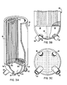
- a nuclear steam generator 60 of the type found in the art is shown in Figures 3A, B and C, of the attached drawings, as comprising an array of a large number of vertically oriented U-shaped tubes 32.
- the tubes 32 are disposed in a cylindrical portion 46 of the generator 60 whose bottom end is associated with a radiation confining housing or channel head 48, typically having a bottom portion or bowl 49 of a hemi-spherical configuration as shown in Figure 3.
- the channel head 48 is divided by a vertical wall 50 into a first quadrant or portion 58 typically known as the hot leg, and a second quadrant or portion 56 typically known as the cold leg.
- a first or input tube 52 supplies hot steam to the hot leg 58
- an output tube 54 is coupled to the cold leg 56.
- the hot steam entering the hot leg 58 passes into the exposed openings of the plurality of U-shaped tubes 32, passing there- through to be introduced into the cold leg 56.
- the steam entry openings of the tubes 32 are supported within openings of a first semicircularly shaped tubesheet portion 38a, whereas the exit openings of the tubes 32 are supported within openings of a second semicircularly shaped tubesheet portion 38b.
- the tubesheet portions 38a and b are termed the tubesheet 38.
- a defective tube i.e., a tube with an opening therein from which radioactive water may escape
- plugging is carried out by entering a first portion of the channel head 48 to seal first one end of its defective tube 32 and then entering the second portion 56 of the channel head 48 to seal the other end of the tube 32.
- a manway or port 62 is provided by which an operator may enter the hot leg 58, and a manway 64 is provided to enter the cold leg 56.
- Plugging is carried out by first identifying the end of the defective tube 32 and then inserting an explosive type plug, having a cylindrical configuration and being tapered from one end to the other.
- each of the manways 52 and 54 are disposed approximately 45° from the vertically disposed wall 50 in a manner as shown in Figure 3C, and approximately 45° from the horizontal plane of the tubesheet 38 as shown in Figure 3B.
- the channel head is in the order of 10 feet in diameter, the manways 16 inches in diameter, and the input and output tubes 52 and 54 three feet in diameter.
- the difficulty in plugging the ends of the tubes 32 arises in that there are a large number of such tubes 32 typically being in the order of 3,500 to 4,500 tubes.
- an observation is made within the cylindrical portion 46 of the steam generator 60 to locate that defective tube noting its position within the array of tubes 32 by its row and column.
- the operator enters the channel head 48 to search for the defective tube 32 by counting the rows and columns to that defective tube 32 of the array known to be defective. Searching for a particular defective tube 32 is tedious under the conditions that exist within the channel head 48.
- the temperature within the channel head 48 is in the order of 120° to 130°F with a 100% humidity.
- a light beam source e.g. a laser
- the laser is steerable by an operator or a computer remote control so that its projected beam falls upon a particular tube, thus identifying that tube to the operator.
- the orientation of the laser is steerable by the operator and can be made to point to a particular tube.
- a video camera is also disposed within the channel head to view the array so that the operator can steer or orient the laser so that its beam falls upon the tube of interest.
- the laser or light source is coupled to appropriate position sensors, which provide output signals indicative of the laser beam orientation; such position signals are in turn used to provide the coordinates of the identified tube.
- position sensors which provide output signals indicative of the laser beam orientation; such position signals are in turn used to provide the coordinates of the identified tube.
- position sensors which provide output signals indicative of the laser beam orientation; such position signals are in turn used to provide the coordinates of the identified tube.
- such systems are subject to error in that the operator may misinterpret which tube the light spot has fallen upon in that the beam cannot be made to be reflected from the center of a tube unless it is plugged solid so that'the tube may reflect light.
- such systems require the operator to not only orientate the light source but also the video camera, unless additional servo controls are applied to the video camera.
- U-S. Patent 4,146,924 discloses a system involving a plurality of video cameras whose output signals are applied to a computer, which in turn calculates a set of coordinates of an object as sighted by the video cameras, within a field. Hence, the operation of this system requires the use of at least two video cameras and the placement of a visual programming device, whereby a computation of the coordinates of the object can be achieved.
- the invention resides in an apparatus for identifying one element of a plurality of elements disposed within a field, said apparatus comprising sighting means defining a line of sight to intersect one element of said plurality of elements and mounted to be operator manipulated so that said line of sight may intersect any one element of said plurality of elements, said sighting means being variably disposed in an unknown position with respect to said field, whereby a reference line is formed between said unknown position and said field; orientation sensing means coupled to said sighting means for providing a signal indicative of the angle between said reference line and said line of sight; and data processing means responsive to said angle signal for identifying the position within said field of said one object sighted by said sighting means.
- the sighting device may take the form of a video camera that is disposed within the environment, and there is further included a display device in the form of a cathode ray tube (CRT) that is disposed externally of the dangerous environment.
- CTR cathode ray tube
- the operator may view upon the CRT the image seen by the video camera and may sight the video camera with the aid of a reticle imposed between the sighted field and the video camera, whereby when the reticle is aligned with the element as viewed upon the CRT, the output of the orientation sensing means identifies with a high degree of accuracy the position of the element.
- the element-identifying apparatus is variably disposed with respect to the array of elements, all of the elements lying within a plane.
- the sighting device is aligned with at least three elements within the known plane, whereby corresponding reference lines between the sighting device and the three elements are defined. Subsequently, the sighting device is aligned with respect to a further element within the plane, whose position is not known, to establish a reference line therebetween.
- the orientation sensing means provides an output signal indicative of the position of the new reference line, whereby the position and in particular the coordinate position of the unknown element within the array plane may be determined.
- the output of the orientation sensing means in the form of resolvers coupled to the video camera is applied to a computer which calculates the X,Y coordinates corresponding to the row and column in which a tube of a nuclear steam generator is disposed within the plane of the tubesheet.
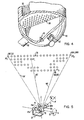
- a mapping and identifying system 10 comprising a video camera 12 that is mounted upon a gimbal, as is well known in the art to be rotatable about a first axis 13 and a second axis 15 disposed perpendicular to the first axis 13, (see Figures 5 and 6) whereby the video camera 12 may be variably disposed to sight any of a plurality of elements or tubes 32, as shown in Figure 3.
- the elements or tubes 32 are a part of a nuclear steam generator 60 (see Figures 3 and 4) and are disposed within a channel head 48, a confined area that is highly radioactive.
- the video camera 12 may be mounted either on a nozzle cover or a fixture referenced to the manway, or placed on the bottom of the bowl 49.
- the video camera 12, as shown in Figures 1 and 5, is associated with gimbal motors identified in Figure 1 by the numeral 18 and more specifically in Figure 5, as a first gimbal motor 18a that serves to pan the video camera 12 about the Y-axis 13, and a second gimbal motor 18b that serves to tilt the video camera 12 about the X-axis 15.
- the gimbal motors 18a and b are illustratively driven by digital type signals of the type that are generated by a systems control 28 and each responds incrementally to the control signals derived from the systems control 28 to an accuracy of at least one part in 1000 resolution over the total angle of rotation about each of the axes 13 and 15. As will be explained later, it is necessary to scan a field or array 38 and to sight with great accuracy the video camera 12 on those elements disposed at the most oblique angle, i.e., a far corner of the field 38, as shown in Figure 5.
- the video camera 12 is associated with a lens 14 having a reticle 16 or cross hairs 16a and b, as illustrated in Figure 2.
- Figure 2 represents a displayed image of the image as seen by the video camera 12.
- the video signal output from the camera 12 is applied to a set of camera controls 26 that outputs a signal to a typical monitor in the form of a CRT 24 to display the image sighted upon by the video camera 12.
- This image 24' is shown in Figure 2 and illustrates the view seen by the video camera 12 as it sights upon the field 38 of tubes 32.
- one of the tubes 32 having the coordinates X,Y is sighted upon, i.e., the video camera 12 is steered or adjustably disposed so that a center point or point of intersection 16c of the cross hairs 16a and 16b is precisely aligned with the tube 32X, Y.
- a set of overlay signals indicating the coordinate position of the sighted tube 32X, Y within the field 38 is also displayed as the CRT image 24'.
- a microprocessor 22 generates and applies such overlay signals to the monitor 24.
- the gimbal motors 18a and 18b are associated with corresponding gimbal angle sensors 20a and 20b to provide output signals to the microprocessor 22, indicative of the angle of rotation of the video camera 12 with respect to the X-axis 15 and the Y-axis 13.
- a gimbal angle sensor 20a is associated with the gimbal motor 18a and measures the pan angle 8 that is formed between a line of sight of the camera 12 as it is rotated about the X-axis 15 with respect to the reference lines.
- a gimbal angle sensor 20b is associated with the gimbal motor 18b and measures the tilt angle as formed between the line of sight of the video camera 12 and the Y-axis 13.
- the output signals or manifestations indicative of the pan angle 8 and the tilt angle are applied to the microprocessor 22, as shown in Figure 1.
- Each of the gimbal angle sensors 20a and 20b may take the form of resolvers that provide an analog output signal in the form of a phase shifted sine wave, the phase shift being equal to the angles of rotation 8 and ⁇ , respectively.
- the output signals of the sensors 20 are applied to a resolver-to-digital converter 19 which provide, illustratively, a 12-bit digital output that is applied to an input/output (I/O) device 21, before being applied to the microprocessor 22.
- I/O input/output
- the microprocessor 22 includes as is well known in the art a programmable memory illustratively comprising a random access memory (RAM) that is loaded with a program for converting the input signals indicative of the pan and tilt angles 8 and ⁇ into an output manifestation indicative of the row/column indices or coordinates of that unknown tube 32 within the field 38 that has been sighted by the video camera 12.
- RAM random access memory
- the microprocessor 22 In order to provide the row/ column coordinates of the sighted tube 32, the microprocessor 22 must first define or locate the plane of the array or tubesheet, i.e., that plane being defined by the ends of the tubes 32 as shown in Figure 5, with respect to the system 10.
- the video camera 12 is sighted upon at least three data reference or known points PT 1 , PT 2 and PT 3 ; these points may be those tubes 34, 36 and 40 that are disposed at the corner locations of the tubesheet plane or array 38 of tubes 32.
- the points PT 1 , PT 2 and PT 3 are fixed or known points, and the distances d 12' d 13 and d 23 therebetween are known.
- the mapping and identifying system 10 may be disposed in any of a variety of positions with respect to the tubesheet plane 38.
- the system 10 is typically disposed within the channel head 48 in a hurried manner in that the operator opens the manway 62, as shown in Figure 4, and hurriedly places the system 10 upon the floor or bottom of the channel head 48, without exercising great care as to its relative position with regard to the tubesheet plane 38.
- the video camera 12 is sighted upon the known points PT I , PT 2 and PT 3 as are formed by the known ends of the tubes 34, 36 and 40, whereby the relative position of the system 10 with respect to the tubesheet plane 38 may be established.
- the video camera 12 is sighted along three reference lines 34', 36' and 40'; these reference lines establishing reference or unit vectors that define with a high degree of precision the relative position of the mapping and identifying system 10 to the tubesheet plane 38.
- the microprocessor 22 utilizes the set of output signals indicative of the ⁇ 1 , ⁇ 1 ; ⁇ 2, ⁇ 2; and ⁇ 3 , ⁇ 3 as derived from the gimbal angle sensors 20a and 20b respectively to define the reference or unit vectors along the reference lines 34', 36' and 40' toward the points PT 1 , PT 2 and PT3, respectively.
- the operator orients the video camera 12 along a sight line 42' to sight an unknown tube at point PT i .
- the 8. and ⁇ i outputs as now derived from the sensors 20a and 20b define a vector along the sight line 42', whereby the microprocessor 22 may calculate the position in terms of the X,Y coordinates of that unknown tube 32 lying at the point PT i . As shown in Figure 2, the microprocessor 22 superimposes the calculated values of these coordinates upon the CRT 24.
- suitable means are provided whereby the video camera 12 may be oriented to sight along the sight line 42' any of the elements or tubes 32 within the field 38.
- a suitable control in the form of a joystick 30 that may be readily grasped by the operator to selectively orient the video camera 12.
- the positioning control signals as provided by the joystick 30 are applied to the systems controls 28 which in turn apply signals to the gimbal motors 18a and 18b to move the camera 12, i.e., to rotate the camera in either direction about its vertical axis 13 and/or about its horizontal axis 15.
- the operator manipulates the joystick 30 while viewing the CRT image 24' until the point of intersection 16c of the reticle 16 is aligned with the element or tube 32 of interest. At that point, the displayed coordinate position indicates to the operator the exact coordinate position of the tube 32. Thereafter, the operator may readily enter the radioactive area within the channel head 48 and proceed directly to the identified tube 32. It is also contemplated within the teachings of this invention that any coordinate system other than the X,Y Cartesian system may be adopted without departing from the teachings of this invention.
- a target having a sighting point may be attached to the tube 32 in a manner that the sighting point may be viewed directly by the video camera 12.
- the sighting point must bear a fixed relationship to the tube 32 to be sighted, and the relationship in terms of an "offset" can be entered into the microprocessor 22, whereby the microprocessor 22 can calculate the coordinate position of the sighted tube 32 based upon a sighting of the tube's sighting point and then adding in the known "offset" whereby the coordinates of the sighted tube 32 may be readily calculated and displayed upon the CRT 24.
- the target may be formed by a cylinder of known radius that is mounted in a concentric manner close to the end of the tube 32.
- the offset would equal the radius so that when the operator sights the video camera 12 upon the edge of the cylinder, the microprocessor 22 "adds" the cylinder radius to the calculated position based upon the cylinder edge sighting to provide a correct coordinate position of the tube 32 itself.
- a hand-held probe or target may be inserted into an end of a tube 32, whereby the operator could sight the video camera 12 on the hand-held probe. It is contemplated that the probe would be aligned with the peripheral surface of the tube 32 so that the offset to be used by the microprocessor 22 would correspond to the tube's radius, whereby the coordinate position of the tube's center may be readily calculated.
- the video camera and the camera control 26 may take the form of a Vidicon type tube as manufactured by Sony Corporation, under their designation AVC 7400
- the gimbal mounting and gimbal motors 18 to permit rotation about the Y-axis 13 and X-axis 15 may take the form of such apparatus as manufactured by Clifton Precision, under their designation No. 08DM-1
- the lens 14 with reticle may take the form of a zoom type lens as manufactured by Vicon Corporation, under their designation No. V11.5-90MS
- the gimbal angle sensors and the resolver-to-digital converter 19 may take the form of the resolver and converter as manufactured by Computer Conversion Company, under their designation Nos.
- the input/output device 19 may take the form of that device as manufactured by Interactive Structures under their designation No. DI09
- the microprocessor 22 may take the form of an Apple II Plus microprocessor as manufactured by Apple Computer under their designation No. A2S1048, and the systems controls 28 and the joystick 30 may take the form of an "Apple" compatible joystick as manufactured by T. G. Products, Inc.
- the reference lines are defined by three sets of camera angles 1) ⁇ 1 , ⁇ 1 , to define the reference line 34'; 2) 8 2 , ⁇ 2, to define the reference line 36'; and 3) ⁇ 3 , ⁇ 3 to define reference line 40'.
- these angles and reference lines 34', 36' and 40' may be translated into unit vectors e l , e 2 and e 3 in accordance with the following transformation: From transformation (1), it is seen that any unit vector e i may be defined in terms of its components along the X, Y, and Z axes as shown in Figure 6.
- the X, Y and Z com- ponents e ix , e iy , and e. iz of the vector e. may be expressed by the following formulas:
- the above-defined unit vectors e 1 , e 2 , e 3 are dimensionless and in order to define the distance from the video camera 12 to each of the points PT 1 , PT 2 and PT 3 , length multipliers or scalers ⁇ 1 , ⁇ 2 and ⁇ 3 are defined as shown in Figure 6, i.e., the vector from the coordinate position 0,00 to PT 1 is ⁇ 1 e 1 .
- the distance d 12 between points PT 1 and PT 2 , the distance d 13 between points PT 1 and PT 3 , and the distance d 23 between point PT 3 and PT 2 are defined by the following equations:
- the ⁇ 1 , ⁇ 2 , and ⁇ 3 are unknown whereas the distances d 12 , d 13 and d 23 may be measured from the known geometry of the tubesheet plane 38 of the tubes 32.
- the set (3) of equations may be solved for the values of ⁇ 1 , ⁇ 2 and ⁇ 3 , whereby the relative position of the tubesheet plane 38 may be defined with respect to the video camera 12, and an arbitrary point PT i corresponding to an unknown tube 32 may be located and defined in accordance with a linear combination of the vectors ⁇ 1 e 1 , ⁇ 2 e 2 , ⁇ 3 e 3 ; vectors as lie along the reference lines 34', 36' and 40', by the following expression: where PT 1 defines a vector corresponding to that vector ⁇ i e i and PT i defines a vector corresponding to ⁇ 1 e 1 , and ⁇ li ⁇ 2i and ⁇ 3i form a set of linear scalers to define that vector PT i as disposed along the reference line 42' to the unknown point PT i within the tubesheet plane 38.
- the transform (4) may also be expressed as follows: wherein ⁇ i defines the set of scalers ⁇ li , a 2i and ⁇ 3i' P is an operator and the term P ⁇ i defines a vector pointing toward the unknown point PTi.
- ⁇ i defines the set of scalers ⁇ li , a 2i and ⁇ 3i' P is an operator and the term P ⁇ i defines a vector pointing toward the unknown point PTi.
- the expression (4) defining the vector PT i may be defined in terms of the vector notation ⁇ i e i as follows:
- the vector to the unknown point PT . may also be defined in terms of a matrix operator L as follows: where the operator matrix L may be expressed as follows: wherein e ix , e iy and e lx define the X, Y and Z components of each of the unit vectors e 1 , e 2 and e 3 .
- the unit vector e i as disposed along the sight line 42' as shown in Figure 6 may be obtained by normaliz- ing the expression ⁇ i e i in accordance with the following:
- the output signals of the angle sensors 20a and 20b indicative of the values of ⁇ i and ⁇ i respectively, when the tube 12 is disposed to sight along sight line 42' to the unknown point PT., are measured variables, which are used to define the following expressions by using the following inverse vector to angle transformation:
- the above expressions (11) and (12) directly relate the output signals of the angle sensors 20a and 20b indicative of ⁇ i and ⁇ i to the X, Y and Z components of the unit vector e i oriented towards the unknown point PT i .
- expressions (11) and (12) given above define the relative position of the system 10 with respect to the tubesheet plane 38 and in particular defines the orientation or direction of the unit vector e i the unknown point PT i .
- the unit vector e i which points to the unknown point PT i , and is derived from the measured angles ⁇ i and ⁇ i to a set of coordinate positions, e.g., the X and Y coordinates or column and row position of the unknown tube 32 within the tubesheet plane 38.
- the unit vector e i is defined in accordance with ⁇ scalers that is related to the coordinate positions of the unknown point PT i within the tubesheet plane 38 as follows:
- Expression (13) defines the vector e i in terms of the reference unit vectors e1 e 2 , and e 3 , and the values of ⁇ 1 , ⁇ 2 , and ⁇ 3 .
- the reference unit vectors e 1 , e 2 , and e 3 are defined respectively in terms of the sets of angles ⁇ 1 , ⁇ 1 ; ⁇ 2 , ⁇ 2 , and ⁇ 3 , ⁇ 3 as obtained from the sensors 20.
- the values of ⁇ 1 , ⁇ 2 , and ⁇ 3 are derived by solving simultaneously three equations taken from the expression (3) above and expressions (20), (21) and (22) below.
- ⁇ 1 , ⁇ 2 , and ⁇ 3 are functions of the measured sets of angles ⁇ 1 , ⁇ 1 ; ⁇ 2 , ⁇ 2 and ⁇ 3 , ⁇ 3 and the known distances d 12 , d 23 and d 13 as shown in Figure 6.
- ⁇ is a scalar set of numbers relating the values of ⁇ 1 , ⁇ 1 ; ⁇ 2 , ⁇ 2 , and ⁇ 3 , ⁇ 3 , and ⁇ 1 , ⁇ 2 , and ⁇ 3 to the unit vector ei, which is defined in terms of ⁇ i , ⁇ i .
- each of the transforms as seen in expression (13) is divided by the inverse or reciprocal of the matrix operator L, i.e., L -1 , to provide the following expression:
- ⁇ i is defined by the following expression:
- the scalar operator ⁇ i is transformed to the special case wherein the end points of the vectors ⁇ 1i , ⁇ 2i and ⁇ 3i lie in the tubesheet plane 38 by the following expression:
- the denominator of the expression (16) indicates a summarizing operation in accordance with the following expression: 1
- the converting of the scalar ⁇ i to ⁇ i by the expression (16) ensures that the following condition is met: and further constrains all points defined by the vector to lie within the tubesheet plane 38.
- ⁇ 1 i is a scalar defined in terms of the three dimensional values ⁇ 1 , ⁇ 2 , and ⁇ 3 as taken from the expression (13) and the values of ⁇ i , ⁇ i , and relates these values to the two dimensions of the tubesheet plane 38.
- the matrix operator P as defined above by expression (5) is seen to be an ordered set or three-by-three array of numbers describing the known points PT 1 , PT 2 , and PT 3 in the tubesheet plane 38 and is used by the following expression to relate any vector e i to the points in the tubesheet plane 38: where PT i is the coordinate position of the unknown point as pointed to by vector in terms of its X,Y coordinates within the tubesheet plane 38.
- expression (19) demonstrates the relationship between the measured camera angles ⁇ i and ⁇ i , which define , and the calculated values of ⁇ 1 , ⁇ 2 and ⁇ 3 (as derived from the measured angles ⁇ 1 , ⁇ 1 ; ⁇ 2 , ⁇ 2 and ⁇ 3 , ⁇ 3 ) to the X,Y coordinate position of the unknown point in the tubesheet plane 38.
- the unknown scalars or length multipliers ⁇ 1 , ⁇ 2 and ⁇ 3 are a function of the known distances d 12 , d 13 , and d 23 , or d kl where k and l are the end points of the "d" distances and may be expressed by the following expression:
- the values of ⁇ 1 , ⁇ 2 , ⁇ 3 may be provided.
- the dis- tances d 12 , d13 and d 23 correspond to the distances between the tubes 34 and 36, 36 and 40 and 34.
- the expression (20) may be solved by using a Newton-Raphson procedure wherein an initial estimate of the distances ⁇ 1 (o) , ⁇ 2 (o) , ⁇ 3 (o) is assumed.
- the distance equations in accordance with expression (20) - may be expanded in a linear Taylor series about the initial estimate.
- the resultant linear equations are solved for the ⁇ i changes ⁇ 1 , ⁇ 2 , ⁇ 3 , which are then added to the initial guesses. This procedure is repeated or reiterated until there is convergence. It has been found that at most five iterations are required to obtain an accuracy of 15 decimal places of the value of ⁇ i starting with a reasonable estimate ⁇ (o) .
- ⁇ k is added to the previous estimate resulting from-the Taylor series expansion, which may be expressed as follows: where The notation cos (e k , e l ) refers to the cosine of the angle between the vectors e k and e Q , and may be derived, as is well known in the art, by taking the dot product between the vectors and .
- the microprocessor 22 has a RAM that is programmed with a program written in the well-known BASIC language to effect the various steps for calculating the reference vectors ⁇ 1 , ; ⁇ 2 , and ⁇ 3 , based upon three sets of angles ⁇ 1 , ⁇ 1 ; ⁇ 2 , ⁇ 2 and ⁇ 3 , ⁇ 3 as well as the known distances d 12 , d 13 and d 23 between three reference points PT 1 , PT 2 and PT 3 within the tubesheet plane 38, as well as to effect the calculation of the coordinate points X,Y within the tubesheet plane 38 of the unknown point PT i based upon the measurements of the angles 8 . and ⁇ i from the angle sensors 20a and b.
- An illustrative example of a particular program in the noted language is set out below as follows:
- the steps at lines 10 to 95 describe an input subroutine whereby the outputs from the gimbal sensors 20 and in particular the resolvers are converted into digital numbers by the converter 19 and input into port 3 of the microprocessor 22.
- the steps at lines 60 and 70 operate on the output of the resolver or angle sensors 20 to subtract the inherent shift angle of the phase angle from a reference point, which shift angle is dependent upon the particular sensors 20 incorporated in the system 10.
- the steps at lines 100 to 150 initialize port 3 of the microprocessor 22.
- the steps at lines 240 to 260 cause a message to be displayed upon the CRT 24 telling the operator to sight the video camera 12 or the reference tubes 34, 36 and 40, identifying these tubes within the tubesheet plane 38 by their row and column as 1,1; 1,100 and 48,40.
- the steps beginning at line 335 permits the operator to manipulate the joystick 30 to input the three sets of angles ⁇ 1 , ⁇ 1 ; ⁇ 2 , ⁇ 2 and ⁇ 3 , ⁇ 3 .
- angle signals ⁇ 1 , ⁇ 1 for the sighting along reference line 34', angle signals ⁇ 2 , ⁇ 2 for the sighting along sighting line 36', and angle signals ⁇ 3 , ⁇ 3 for the sighting along sighting line 40' are stored by the step at line 348 in a dedicated location of the microprocessor's RAM.
- the steps at lines 390 to 450 calculates the X , Y and Z components of the unit vectors , , in accordance with the equation (2), thus providing three component values for each vector for a total of nine values.
- the step at line 900 calls the initial estimates for the length multipliers or scalers ⁇ 1 (o) , ⁇ 2 (o) , ⁇ 3 (o) from a known location in the RAM, and the step at line 910 reads out the known distances d 12 . d 13 and d 23 as shown in Figure 6 from the microprocessor's RAM.
- the steps at lines 920 to 940 calculate the cosine values of the angles between the unit vectors e 1 , e2, e3 as by taking the dot product of the two vectors, i.e., the cosine of the angle between the vectors e 1 and e 2 is equal to e 1 , e 2 .
- the step at line 970 displays the initially assumed values of the scalers ⁇ (o) , and in the steps as shown at lines 1000 to 1480, the iteration solving of expressions (21) and (22) in accordance with the Newton-Raphson procedure is effected.
- a first approximation of the distance d kl (o) is carried out by the steps at line 1100 to 1130 in accordance with the expression (21).
- the difference of d kl - d kl (o) is calculated and the difference value is used to solve by the steps of lines 1200-1260 the three equations defining the given distances d 12 , d 13 and d 23 ac- cording to the expression (20) for the unknown values of ⁇ ⁇ and ⁇ l .
- step at line 1280 the matrix of these three equations is formed in accordance with the expression (21), and in step 1320, an inversion thereof is taken by going to subroutine 6000, which performs an inversion operation by the well-known Gauss Jordan elimination process before returning to the main procedure.
- step 1320 each side of the expression (21) is multiplied by the inverted matrix to solve for the unknown values of ⁇ ⁇ and ⁇ l that are to be used in the above Taylor series expansion.
- the calculated values of ⁇ are added to the previous values of X, before in the step at line 1480, the square root of the calculated values of ⁇ ⁇ , ⁇ l is squared and the square root of their sum is taken; thereafter the calculated sum is compared with an arbitrary small value and if less, it is known that the iteration error has grown to a sufficiently small level to achieve the desired degree of accuracy of the values of ⁇ 1 , ⁇ 2 , ⁇ 3 , i.e., the three equations according to the expression (21) have been solved for ⁇ 1 , ⁇ 2 , ⁇ 3 .
- step at line 1497 values of each of ⁇ i , e i are obtained so that they may be inserted into expression (14) to solve for .
- step at 1540 the matrix L is called and the inversion thereof is calculated by the subroutine called at line 1560 in accordance with the well-known Gauss Jordan elimination procedure.
- the program begins at the step of line 1580 to calculate the coordinates of the unknown point, i.e., PT i .
- the vector e i is called as follows: First, the output of the gimbal sensors 20 for the angles ⁇ i and ⁇ i and the X, Y and Z component values of the vector are calculated in the steps at line 1650 to 1660 to thereby define the vector in accordance with the expression (L) stated above.
- the step at line 1710 calculates the vector matrix by taking the product of the matrix L -1 and the vector in accordance with ex- pression (14). In order to reduce the vector scaler to the special case to ensure that the points PT 1 , PT 2 , PT 3 lie in the tubesheet plane 38, the value of is calculated at the step of line 1750 in accordance with the expression (16).
- the coordinate values as obtained from the expression (19) are calculated.
- the coordinate values of the unknown point PT i in terms of the row and column or X and Y values of the unknown tube 32 are displayed upon the CRT 24.
- the systems controls 28 which respond to the operator manipulated joystick 30, could be applied to the microprocessor 22 whereby the microprocessor 22 directs the gimbal motors 18a and b to a known position.
- the tilt and pan angles and 8 are set by the microprocessor 22 and it would not be necessary to employ the gimbal angle sensors 20 as shown in the embodiment of Figure 1.
- the microprocessor 22 may be coupled to a video tape recorder, whereby the tube selection process and the indicated coordinate values can be readily stored.
- mapping and identifying system that has significant advantages over the prior art systems.
- the present system eliminates the need for the operator to manipulate both a light source and an image sensor. Rather in accordance with the teachings of this invention, the operator manipulates only a sighting means in the form of a video camera.
- the built-in reticle provides a drift-free reference for all sightings and permits the use of readily available video equipment including a video camera, camera controls and display equipment.
- the gimbal motors and sensors are readily available devices that provide digital output signals that are readily adapted to be processed by the microprocessor 22.
- the microprocessor 22 performs the repetitive operations of converting the gimbal angle signals to row/column manifestations, as well as the calculation of the reference or plane in which the tube ends are disposed.
- a significant advantage of this system is that the length of stay within the channel head or housing in which there is a high level of radiation, is substantially reduced in that the operator may readily find the tube of interest.
Landscapes
- Physics & Mathematics (AREA)
- Engineering & Computer Science (AREA)
- High Energy & Nuclear Physics (AREA)
- Thermal Sciences (AREA)
- Mechanical Engineering (AREA)
- General Engineering & Computer Science (AREA)
- General Physics & Mathematics (AREA)
- Monitoring And Testing Of Nuclear Reactors (AREA)
- Length Measuring Devices By Optical Means (AREA)
- Image Analysis (AREA)
- Investigating Or Analyzing Materials By The Use Of Ultrasonic Waves (AREA)
- Investigating Or Analyzing Materials By The Use Of Magnetic Means (AREA)
- Image Processing (AREA)
- Apparatus For Radiation Diagnosis (AREA)
Applications Claiming Priority (2)
| Application Number | Priority Date | Filing Date | Title |
|---|---|---|---|
| US06/289,955 US4503506A (en) | 1981-08-05 | 1981-08-05 | Apparatus for mapping and identifying an element within a field of elements |
| US289955 | 1981-08-05 |
Publications (3)
| Publication Number | Publication Date |
|---|---|
| EP0071977A2 true EP0071977A2 (de) | 1983-02-16 |
| EP0071977A3 EP0071977A3 (en) | 1983-07-06 |
| EP0071977B1 EP0071977B1 (de) | 1986-11-20 |
Family
ID=23113906
Family Applications (1)
| Application Number | Title | Priority Date | Filing Date |
|---|---|---|---|
| EP82107051A Expired EP0071977B1 (de) | 1981-08-05 | 1982-08-04 | Gerät zum örtlichen Erfassen und Identifizieren eines Körpers in einer Körpermenge |
Country Status (11)
| Country | Link |
|---|---|
| US (1) | US4503506A (de) |
| EP (1) | EP0071977B1 (de) |
| JP (1) | JPS5833105A (de) |
| KR (1) | KR900005638B1 (de) |
| CA (1) | CA1188771A (de) |
| DE (1) | DE3274399D1 (de) |
| ES (1) | ES514735A0 (de) |
| IL (1) | IL66302A (de) |
| PH (1) | PH19048A (de) |
| YU (1) | YU167482A (de) |
| ZA (1) | ZA824845B (de) |
Cited By (3)
| Publication number | Priority date | Publication date | Assignee | Title |
|---|---|---|---|---|
| US4729423A (en) * | 1984-12-14 | 1988-03-08 | Framatome | Process and apparatus for the optical checking of the shape and dimensions of the ends of tubes in a steam generator |
| US5594764A (en) * | 1995-06-06 | 1997-01-14 | Westinghouse Electric Corporation | Automated video characterization of nuclear power plant components |
| CN101782370A (zh) * | 2010-03-09 | 2010-07-21 | 哈尔滨工业大学 | 基于usb摄像头的测量定位方法及测量运动物体的运动轨迹的方法 |
Families Citing this family (20)
| Publication number | Priority date | Publication date | Assignee | Title |
|---|---|---|---|---|
| JPS59155591U (ja) * | 1983-04-05 | 1984-10-18 | 三菱重工業株式会社 | 原子力設備の機器開口部遮蔽装置 |
| JPS6022609A (ja) * | 1983-07-19 | 1985-02-05 | Toyota Motor Corp | 計測機器におけるテレビカメラ位置ずれ検知方法及び装置 |
| JPS6042631A (ja) * | 1983-08-19 | 1985-03-06 | Mitsubishi Electric Corp | 水漏れ監視装置 |
| US4661309A (en) * | 1984-02-13 | 1987-04-28 | Combustion Engineering, Inc. | Equipment transporter for nuclear steam generator |
| US4576123A (en) * | 1984-07-20 | 1986-03-18 | Westinghouse Electric Corp. | Workpiece positioning apparatus with plural sensors |
| JPS6281508A (ja) * | 1985-10-05 | 1987-04-15 | Kawasaki Heavy Ind Ltd | 光学式3次元位置計測装置 |
| CA1338909C (en) * | 1987-03-05 | 1997-02-11 | Curtis M. Brubaker | Radio control toy |
| DE3741632A1 (de) * | 1987-12-05 | 1989-06-22 | Noell Gmbh | Verfahren und vorrichtung zum erkennen und ansteuern eines raumzieles |
| US4891767A (en) * | 1988-06-02 | 1990-01-02 | Combustion Engineering, Inc. | Machine vision system for position sensing |
| EP0483383A4 (en) * | 1990-05-19 | 1993-08-04 | Kabushiki Kaisha Topcon | Method of tridimensional measuring, reference scale and self-illuminating reference scale for tridimensional measuring |
| US5719622A (en) * | 1996-02-23 | 1998-02-17 | The Regents Of The University Of Michigan | Visual control selection of remote mechanisms |
| US5878151A (en) * | 1996-10-31 | 1999-03-02 | Combustion Engineering, Inc. | Moving object tracking |
| US5887041A (en) * | 1997-10-28 | 1999-03-23 | Westinghouse Electric Corporation | Nuclear power plant component identification and verification system and method |
| US6529623B1 (en) | 1999-08-31 | 2003-03-04 | Advanced Micro Devices, Inc. | Stepper lens specific reticle compensation for critical dimension control |
| JP4581512B2 (ja) * | 2004-07-02 | 2010-11-17 | オムロン株式会社 | 3次元画像処理装置、光軸調整方法、光軸調整支援方法 |
| CN100582641C (zh) * | 2005-04-30 | 2010-01-20 | 江从铨 | 汽轮发电机凝汽器在线自动冲洗装置及方法 |
| US20070021207A1 (en) * | 2005-07-25 | 2007-01-25 | Ned Ahdoot | Interactive combat game between a real player and a projected image of a computer generated player or a real player with a predictive method |
| US20070021199A1 (en) * | 2005-07-25 | 2007-01-25 | Ned Ahdoot | Interactive games with prediction method |
| JP2010122054A (ja) * | 2008-11-19 | 2010-06-03 | Mitsubishi Heavy Ind Ltd | 空間内壁の作業位置特定装置及びその方法 |
| JP2012184930A (ja) * | 2011-03-03 | 2012-09-27 | Ihi Corp | 基準線設定方法、基準線設定装置 |
Family Cites Families (18)
| Publication number | Priority date | Publication date | Assignee | Title |
|---|---|---|---|---|
| US980001A (en) * | 1906-09-27 | 1910-12-27 | James D Millar | Centrifugal sluicing-machine. |
| US3041393A (en) * | 1958-06-30 | 1962-06-26 | Grundig Max | Television system for inspecting the inner walls of enclosed spaces |
| US3637997A (en) * | 1968-12-06 | 1972-01-25 | Tektronix Inc | Graphic display system |
| DE2014998A1 (de) * | 1970-03-28 | 1971-10-21 | Siemens Ag | Optisches Anzeigegerät zur mehrdimensionalen Darstellung der Kennwerte von Brennelementen und Steuerstäben eines Kernreaktors |
| US3810138A (en) * | 1972-01-10 | 1974-05-07 | Westinghouse Electric Corp | Interpolative sensor output visual map display system |
| US3783189A (en) * | 1972-06-01 | 1974-01-01 | Atomic Energy Commission | Television system for precisely measuring distances |
| US3994173A (en) * | 1973-11-12 | 1976-11-30 | Combustion Engineering, Inc. | Remote orientation of a probe in a tubular conduit |
| US4021840A (en) * | 1975-01-24 | 1977-05-03 | General Dynamics Corporation | Seam tracking welding system |
| US4146924A (en) * | 1975-09-22 | 1979-03-27 | Board Of Regents For Education Of The State Of Rhode Island | System for visually determining position in space and/or orientation in space and apparatus employing same |
| UST980001I4 (en) * | 1976-03-18 | 1979-03-06 | Electric Power Research Institute | UV Viewing through sodium coolant |
| US4074814A (en) * | 1976-03-26 | 1978-02-21 | Combustion Engineering, Inc. | Method and apparatus for controlling surface traversing device |
| DE2643810C2 (de) * | 1976-09-29 | 1983-08-11 | Licentia Patent-Verwaltungs-Gmbh, 6000 Frankfurt | Verfahren zum Einjustieren |
| US4205939A (en) * | 1978-01-30 | 1980-06-03 | Westinghouse Electric Corp. | Apparatus for remotely repairing tubes in a steam generator |
| US4224501A (en) * | 1978-02-27 | 1980-09-23 | Unimation, Inc. | Teaching arrangement for programmable manipulator |
| US4190857A (en) * | 1978-06-08 | 1980-02-26 | Combustion Engineering, Inc. | Periscope assembly |
| US4231419A (en) * | 1978-07-21 | 1980-11-04 | Kraftwerk Union Aktiengesellschaft | Manipulator for inspection and possible repair of the tubes of heat exchangers, especially of steam generators for nuclear reactors |
| US4347652A (en) * | 1978-10-18 | 1982-09-07 | Westinghouse Electric Corp. | Method for servicing a steam generator |
| FR2482508A1 (fr) * | 1980-05-14 | 1981-11-20 | Commissariat Energie Atomique | Manipulateur et support d'orientation motorise pour un tel manipulateur |
-
1981
- 1981-08-05 US US06/289,955 patent/US4503506A/en not_active Expired - Fee Related
-
1982
- 1982-07-07 ZA ZA824845A patent/ZA824845B/xx unknown
- 1982-07-12 IL IL66302A patent/IL66302A/xx unknown
- 1982-07-16 PH PH27584A patent/PH19048A/en unknown
- 1982-07-19 CA CA000407577A patent/CA1188771A/en not_active Expired
- 1982-08-02 YU YU01674/82A patent/YU167482A/xx unknown
- 1982-08-04 JP JP57135264A patent/JPS5833105A/ja active Granted
- 1982-08-04 ES ES514735A patent/ES514735A0/es active Granted
- 1982-08-04 EP EP82107051A patent/EP0071977B1/de not_active Expired
- 1982-08-04 DE DE8282107051T patent/DE3274399D1/de not_active Expired
- 1982-08-05 KR KR8203529A patent/KR900005638B1/ko not_active Expired
Cited By (3)
| Publication number | Priority date | Publication date | Assignee | Title |
|---|---|---|---|---|
| US4729423A (en) * | 1984-12-14 | 1988-03-08 | Framatome | Process and apparatus for the optical checking of the shape and dimensions of the ends of tubes in a steam generator |
| US5594764A (en) * | 1995-06-06 | 1997-01-14 | Westinghouse Electric Corporation | Automated video characterization of nuclear power plant components |
| CN101782370A (zh) * | 2010-03-09 | 2010-07-21 | 哈尔滨工业大学 | 基于usb摄像头的测量定位方法及测量运动物体的运动轨迹的方法 |
Also Published As
| Publication number | Publication date |
|---|---|
| ZA824845B (en) | 1983-08-31 |
| ES8401663A1 (es) | 1983-12-16 |
| EP0071977A3 (en) | 1983-07-06 |
| PH19048A (en) | 1985-12-11 |
| JPS5833105A (ja) | 1983-02-26 |
| KR900005638B1 (ko) | 1990-08-01 |
| KR840001347A (ko) | 1984-04-30 |
| IL66302A (en) | 1987-02-27 |
| EP0071977B1 (de) | 1986-11-20 |
| CA1188771A (en) | 1985-06-11 |
| DE3274399D1 (en) | 1987-01-08 |
| US4503506A (en) | 1985-03-05 |
| ES514735A0 (es) | 1983-12-16 |
| YU167482A (en) | 1985-04-30 |
| JPH0126481B2 (de) | 1989-05-24 |
Similar Documents
| Publication | Publication Date | Title |
|---|---|---|
| US4503506A (en) | Apparatus for mapping and identifying an element within a field of elements | |
| US5212738A (en) | Scanning laser measurement system | |
| JP3070953B2 (ja) | 空間座標の逐点式測定方法及びシステム | |
| US4255762A (en) | Apparatus for inspecting pipes in a plant | |
| US5784282A (en) | Method and apparatus for identifying the position in three dimensions of a movable object such as a sensor or a tool carried by a robot | |
| US12347575B2 (en) | Systems and methods for laser inspection and measurements | |
| US4831547A (en) | Multi-joint-robot controller for enabling detection of the spatial relationship between a robot and a rotary cable | |
| EP0301019A1 (de) | Verfahren zur dreidimensionalen überwachung des objektraumes. | |
| Altschuler et al. | Measuring surfaces space-coded by a laser-projected dot matrix | |
| US20190129045A1 (en) | Radiation imaging apparatus | |
| Xu et al. | A calibration and 3-D measurement method for an active vision system with symmetric yawing cameras | |
| US11630208B2 (en) | Measurement system, measurement method, and measurement program | |
| CA3028579A1 (en) | Portable survey meter and method | |
| Schneider et al. | Optical 3-D measurement systems for quality control in industry | |
| US20030083844A1 (en) | Optical position sensing of multiple radiating sources in a movable body | |
| JPH0843067A (ja) | 既知の環境内にある乗物の位置及び向きを正確に決定するシステム | |
| US6206891B1 (en) | Device and method for calibration of a stereotactic localization system | |
| Maniere et al. | Vision system dedicated to panoramic three-dimensional scene reconstruction | |
| Wong et al. | 3D metric vision for engineering construction | |
| JPH0428511B2 (de) | ||
| KR19980018382A (ko) | 자동시준방법 및 자동시준장치 | |
| KR102951443B1 (ko) | 이동 플랫폼 탑재형 센서 기반 전방향 방사능 방향 탐지 장치 및 그 방법 | |
| Gaiarsa et al. | Real-time measurement of corner position in binary images | |
| SU754208A1 (ru) | Способ сканирования в стереооптическои системе i | |
| CN120496899A (zh) | 核电站安全壳的缺陷检测方法、装置及电子设备 |
Legal Events
| Date | Code | Title | Description |
|---|---|---|---|
| PUAI | Public reference made under article 153(3) epc to a published international application that has entered the european phase |
Free format text: ORIGINAL CODE: 0009012 |
|
| AK | Designated contracting states |
Designated state(s): BE CH DE FR GB IT LI SE |
|
| PUAL | Search report despatched |
Free format text: ORIGINAL CODE: 0009013 |
|
| AK | Designated contracting states |
Designated state(s): BE CH DE FR GB IT LI SE |
|
| 17P | Request for examination filed |
Effective date: 19830707 |
|
| ITF | It: translation for a ep patent filed | ||
| GRAA | (expected) grant |
Free format text: ORIGINAL CODE: 0009210 |
|
| AK | Designated contracting states |
Kind code of ref document: B1 Designated state(s): BE CH DE FR GB IT LI SE |
|
| REF | Corresponds to: |
Ref document number: 3274399 Country of ref document: DE Date of ref document: 19870108 |
|
| ET | Fr: translation filed | ||
| PLBI | Opposition filed |
Free format text: ORIGINAL CODE: 0009260 |
|
| 26 | Opposition filed |
Opponent name: SIEMENS AKTIENGESELLSCHAFT, BERLIN UND MUENCHEN Effective date: 19870819 |
|
| PLBM | Termination of opposition procedure: date of legal effect published |
Free format text: ORIGINAL CODE: 0009276 |
|
| STAA | Information on the status of an ep patent application or granted ep patent |
Free format text: STATUS: OPPOSITION PROCEDURE CLOSED |
|
| 27C | Opposition proceedings terminated |
Effective date: 19880311 |
|
| PGFP | Annual fee paid to national office [announced via postgrant information from national office to epo] |
Ref country code: FR Payment date: 19890622 Year of fee payment: 8 |
|
| PGFP | Annual fee paid to national office [announced via postgrant information from national office to epo] |
Ref country code: SE Payment date: 19900625 Year of fee payment: 9 Ref country code: GB Payment date: 19900625 Year of fee payment: 9 |
|
| PGFP | Annual fee paid to national office [announced via postgrant information from national office to epo] |
Ref country code: BE Payment date: 19900712 Year of fee payment: 9 |
|
| PGFP | Annual fee paid to national office [announced via postgrant information from national office to epo] |
Ref country code: CH Payment date: 19900920 Year of fee payment: 9 |
|
| PGFP | Annual fee paid to national office [announced via postgrant information from national office to epo] |
Ref country code: DE Payment date: 19900929 Year of fee payment: 9 |
|
| PG25 | Lapsed in a contracting state [announced via postgrant information from national office to epo] |
Ref country code: FR Effective date: 19910430 |
|
| REG | Reference to a national code |
Ref country code: FR Ref legal event code: ST |
|
| PG25 | Lapsed in a contracting state [announced via postgrant information from national office to epo] |
Ref country code: GB Effective date: 19910804 |
|
| PG25 | Lapsed in a contracting state [announced via postgrant information from national office to epo] |
Ref country code: SE Effective date: 19910805 |
|
| PG25 | Lapsed in a contracting state [announced via postgrant information from national office to epo] |
Ref country code: LI Effective date: 19910831 Ref country code: CH Effective date: 19910831 Ref country code: BE Effective date: 19910831 |
|
| BERE | Be: lapsed |
Owner name: WESTINGHOUSE ELECTRIC CORP. Effective date: 19910831 |
|
| GBPC | Gb: european patent ceased through non-payment of renewal fee | ||
| REG | Reference to a national code |
Ref country code: CH Ref legal event code: PL |
|
| PG25 | Lapsed in a contracting state [announced via postgrant information from national office to epo] |
Ref country code: DE Effective date: 19920501 |
|
| EUG | Se: european patent has lapsed |
Ref document number: 82107051.3 Effective date: 19920306 |