EP0072039A2 - Balayeuse - Google Patents
Balayeuse Download PDFInfo
- Publication number
- EP0072039A2 EP0072039A2 EP82200489A EP82200489A EP0072039A2 EP 0072039 A2 EP0072039 A2 EP 0072039A2 EP 82200489 A EP82200489 A EP 82200489A EP 82200489 A EP82200489 A EP 82200489A EP 0072039 A2 EP0072039 A2 EP 0072039A2
- Authority
- EP
- European Patent Office
- Prior art keywords
- suction
- opening
- wiping material
- pendulum
- wiping
- Prior art date
- Legal status (The legal status is an assumption and is not a legal conclusion. Google has not performed a legal analysis and makes no representation as to the accuracy of the status listed.)
- Withdrawn
Links
- 238000010408 sweeping Methods 0.000 title claims abstract description 16
- 239000000463 material Substances 0.000 claims abstract description 33
- 241001417527 Pempheridae Species 0.000 claims abstract description 12
- 230000006978 adaptation Effects 0.000 abstract 1
- XLYOFNOQVPJJNP-UHFFFAOYSA-N water Substances O XLYOFNOQVPJJNP-UHFFFAOYSA-N 0.000 description 5
- 229910000746 Structural steel Inorganic materials 0.000 description 2
- 239000000654 additive Substances 0.000 description 2
- 230000000996 additive effect Effects 0.000 description 2
- 230000006835 compression Effects 0.000 description 2
- 238000007906 compression Methods 0.000 description 2
- 239000000428 dust Substances 0.000 description 2
- 238000004140 cleaning Methods 0.000 description 1
- 230000007423 decrease Effects 0.000 description 1
- 230000001419 dependent effect Effects 0.000 description 1
- 238000006073 displacement reaction Methods 0.000 description 1
- 230000000694 effects Effects 0.000 description 1
- 239000002184 metal Substances 0.000 description 1
- 229910052751 metal Inorganic materials 0.000 description 1
- 239000000203 mixture Substances 0.000 description 1
Images


Classifications
-
- E—FIXED CONSTRUCTIONS
- E01—CONSTRUCTION OF ROADS, RAILWAYS, OR BRIDGES
- E01H—STREET CLEANING; CLEANING OF PERMANENT WAYS; CLEANING BEACHES; DISPERSING OR PREVENTING FOG IN GENERAL CLEANING STREET OR RAILWAY FURNITURE OR TUNNEL WALLS
- E01H1/00—Removing undesirable matter from roads or like surfaces, with or without moistening of the surface
- E01H1/08—Pneumatically dislodging or taking-up undesirable matter or small objects; Drying by heat only or by streams of gas; Cleaning by projecting abrasive particles
- E01H1/0827—Dislodging by suction; Mechanical dislodging-cleaning apparatus with independent or dependent exhaust, e.g. dislodging-sweeping machines with independent suction nozzles ; Mechanical loosening devices working under vacuum
- E01H1/0836—Apparatus dislodging all of the dirt by suction ; Suction nozzles
- E01H1/0845—Apparatus dislodging all of the dirt by suction ; Suction nozzles with mechanical loosening or feeding instruments for the dirt to be sucked- up, e.g. brushes, scrapers
Definitions
- sweepers which are used primarily for cleaning streets and sidewalks and are designed as vehicles, it is known to arrange sweeping brushes on the side that hold the wiping material
- a vacuum creates a vacuum in the wiping material container, through which a suction effect is generated in the suction device, so that the wiping material gets into the wiping material container, whereby the air extracted by the turbine emerges again into the open.
- the size of the suction opening in turn depends on the height of the wiping material to be suctioned above the wiping surface, so that ultimately reliable suction is dependent on the size of the suction opening being kept constant, regardless of the height of the wiping material above the wiping surface.
- the object of the present invention was to change the clear width of the suction opening as a function of the height of the wiping material conveyed by the sweeping brushes above the wiping surface.
- this is the case with a sweeper with at least one sweeping brush and a suction device with its suction opening in the region of the wiping material conveyed by the sweeping brush, the suction opening in the form of a passage opening being located partly on the front wall of the suction device as seen in the direction of movement of the sweeper, achieved by at least one pendulum which changes the average cross section of the passage opening.
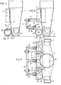
- 1 denotes the intake pipe, which is supported against the wiping surface 3 by means of the rollers 2.
- the suction pipe leads to the wiping material container, not shown, in which a negative pressure is generated by means of a turbine, also not shown.
- On the intake pipe 1 two side wings 4 are attached, which are used to attach one bracket 5 each.
- On each console 5, a tab 6 is attached, in the free End of the axis of rotation 7 for the three flaps 8 serving as a pendulum is mounted.
- the flaps 8 are arranged at a distance from one another, so that a slot 9 is formed between adjacent flaps 8.
- the flaps 8 have at their front end (seen in the direction of movement of the sweeper) an elongated hole 8 b, by means of which they are arranged rotatably about the axis 7.
- Each flap 8 consists essentially of a closed sheet metal profile, which widens towards the intake pipe 1.
- the inlet openings 10 serve to extract the dust whirled up by the sweeping brushes 11.
- a suitable water additive had to accept the disadvantages of an excessive water requirement or that, with too little water added, the dust-water mixture was not extracted. but only led to smearing of the wiping surface.
- the suction pipe 1 has the suction opening, which is composed of the suction slot 13, i.e. the slot-like opening between the end of the suction pipe 1 and the wiping surface 3 and the passage opening 14, i.e. the opening of the suction pipe on its front wall, as seen in the direction of movement of the sweeper.
- the distance between the bottom flap edge 8 a and the wiping surface 3 can be adjusted by a control device which essentially consists of a link 15 assigned to each flap 8 and pivotally connected to the top side of the flap, which link 15 asserts an angle iron 16 attached to the brackets 5 and at their end passing through this angle iron 16 are provided with a thread 17 which serves to fasten the adjusting nut 18.
- the function of such a device is that the wiping material is conveyed through the two opposing sweeping brushes 11 (only one shown in the drawing) into the area of the suction opening 13/14 of the suction pipes 1, in order then by the suction turbine, not shown, through which Intake pipe 1 to get into the wiping material container.
- the passage cross section of the suction opening is now given, inter alia, on the one hand by the distance of the suction pipe mouth from the wiping surface (suction slot 13) and on the other hand the part of the passage opening 14 on the front side of the suction pipe 1 which is left open by the flaps 8.
- the flaps 8 are pivoted counter-clockwise into the position shown by the dashed lines in the drawing by this wiping material 12 and thus release an additional part of the passage opening. As soon as the height of the wiping material 12 decreases, the flaps 8 pivot again under the influence of their own weight and displacement of the elongated hole 8 a relative to the axis 7 into the lower starting position, which is determined by the adjusting nut 18.
- the Pendulum flaps 19 in the form shown in FIGS. 3 and 4, and which differ from flaps 8 according to FIGS. 1 and 2 primarily in that they enter the passage opening 14 with their bent back side 19a . They are also lifted by the wiping material and thus open up an additional part of the passage opening and thus the suction opening. According to the flaps 8 according to FIGS. 1 and 2, the flaps 19 are also provided with inlet openings 10.
- FIG. 1 A simplified embodiment is shown in FIG.
- a roller 21 serving as a pendulum and provided with openings 2la is pivotally suspended by means of the arm 20, which roller 21 is pivoted about its pivot axis 22 into the position shown in dashed lines, depending on the height of the wiping material. The pivoting movement also partially releases the inlet opening.
- each roller 23 designed as a pendulum and provided with openings 23a is rotatably held in a fork 24, which fork in turn is rotatably mounted about a pivot axis 25.
- Each fork 24 is designed as a one-armed lever which can be rotated about the pivot axis 25, each pivot axis being attached to the end of a link 27 which in turn can be pivoted about the axis 26.
- the axles 26 are seated again
- a block 28 which cooperates with the adjusting screw 29 and is connected to the link 27 via a compression spring 30, is fastened to each fork 24.
- the adjusting screw 29 as well the compression springs 30 serve to set the rollers 23 at a desired height above the wiping surface 3. If the rollers 23 hit wiping material, the height of which is greater than the set distance of the rollers 23 from the wiping surface 3, then the rollers 23 pivot in the drawing counterclockwise while simultaneously releasing part of the suction slot and thus enlarging the inlet opening 14. Due to the dead weight of each roller 23, this roller is pivoted back into the set starting position as soon as the lifting force exerted by the wiping material is eliminated.
- a pendulum is provided (here embodied as rollers), which are arranged in front of the passage opening as part of the suction opening and, through the pivoting thereof caused by a certain height of the wiping material, the passage opening is enlarged as long as that Influencing of the pendulum in question by the wiping material continues.
Landscapes
- Engineering & Computer Science (AREA)
- Architecture (AREA)
- Civil Engineering (AREA)
- Structural Engineering (AREA)
- Cleaning In General (AREA)
- Nozzles For Electric Vacuum Cleaners (AREA)
Applications Claiming Priority (2)
| Application Number | Priority Date | Filing Date | Title |
|---|---|---|---|
| CH505281A CH653723A5 (de) | 1981-08-05 | 1981-08-05 | Kehrmaschine. |
| CH5052/81 | 1981-08-05 |
Publications (2)
| Publication Number | Publication Date |
|---|---|
| EP0072039A2 true EP0072039A2 (fr) | 1983-02-16 |
| EP0072039A3 EP0072039A3 (fr) | 1983-11-16 |
Family
ID=4287147
Family Applications (1)
| Application Number | Title | Priority Date | Filing Date |
|---|---|---|---|
| EP82200489A Withdrawn EP0072039A3 (fr) | 1981-08-05 | 1982-04-23 | Balayeuse |
Country Status (2)
| Country | Link |
|---|---|
| EP (1) | EP0072039A3 (fr) |
| CH (1) | CH653723A5 (fr) |
Cited By (6)
| Publication number | Priority date | Publication date | Assignee | Title |
|---|---|---|---|---|
| WO1985001203A1 (fr) * | 1983-09-13 | 1985-03-28 | K.E.W. Industri A/S | Outil de sol pour grands aspirateurs |
| FR2605907A1 (fr) * | 1986-11-03 | 1988-05-06 | Debefi | Dispositif combine d'aspiration et de nettoyage monte sur un vehicule leger autonome pour aspiration de dechets industriels et urbains |
| DE19520778C1 (de) * | 1995-06-07 | 1996-07-18 | Juergen Pierau | Saugvorrichtung für eine Kehrmaschine |
| US5839157A (en) * | 1996-05-06 | 1998-11-24 | Elgin Sweeper Company | Street sweeper pick-up head |
| DE29914329U1 (de) * | 1999-08-16 | 2000-12-28 | FAUN Viatec GmbH, 04668 Grimma | Saugdüse |
| ITMI20111140A1 (it) * | 2011-06-23 | 2012-12-24 | Dulevo Int Spa | Bocca di aspirazione per macchine aspiratrici per pulizia del suolo |
Family Cites Families (14)
| Publication number | Priority date | Publication date | Assignee | Title |
|---|---|---|---|---|
| FR469540A (fr) * | 1914-03-04 | 1914-08-03 | Bruno Leinweber | Machine à balayer les rues |
| DE1096941B (de) * | 1959-01-08 | 1961-01-12 | Schoerling & Co Waggonbau | Durch Unterdruck den Kehricht selbstaufnehmende Kehrmaschine |
| US3201819A (en) * | 1961-11-17 | 1965-08-24 | Lambert Inc | Sweeper |
| GB970674A (en) * | 1962-02-22 | 1964-09-23 | Lacre Ltd | Machine for cleaning street and the like surfaces |
| DE1582158A1 (de) * | 1967-06-05 | 1971-06-09 | Konrad Dr Buck | Saugkopf zum Absaugen unebener Flaechen |
| NL6717778A (fr) * | 1967-12-28 | 1969-07-01 | ||
| DE2006747A1 (de) * | 1970-02-14 | 1971-08-19 | H. Jungheinrich & Co., Maschinenfabrik, 2000 Hamburg | Fahrbare Kehrsaugmaschine |
| FR2077843A1 (fr) * | 1970-02-18 | 1971-11-05 | Materiel De Voirie | Buse d'aspiration pour engin de nettoiement |
| US3675266A (en) * | 1970-12-08 | 1972-07-11 | Tarrant Mfg Co | Vacuum type debris collector with scraper blade |
| DE2217975C3 (de) * | 1972-04-14 | 1980-08-21 | Schoerling Gmbh & Co Waggonbau, 3000 Hannover | An einem Fahrzeug, insbesondere Schienenfahrzeug, angeordnete Einrichtung zum Reinigen von Schotterbetten, Gleisschwellen u.dgl. einer Gleisanlage |
| CH621170A5 (en) * | 1977-01-10 | 1981-01-15 | Sachs Maschinen | Vacuum cleaner |
| DE7731248U1 (de) * | 1977-10-08 | 1978-02-02 | Xaver Fendt & Co, 8952 Marktoberdorf | Von einem fahrzeug zu tragendes geraet zum entfernen von laub u.dgl. von strassen, wegen, plaetzen, rasenflaechen etc. |
| DE2901355C2 (de) * | 1979-01-15 | 1986-01-23 | Schörling & Co Waggonbau, 3000 Hannover | Aufnahmevorrichtung für ein selbstaufnehmendes, mit Unterdruckförderung arbeitendes Kehrfahrzeug |
| US4263693A (en) * | 1979-06-15 | 1981-04-28 | Mekelburg Clayton G | Vacuum cleaner head |
-
1981
- 1981-08-05 CH CH505281A patent/CH653723A5/de not_active IP Right Cessation
-
1982
- 1982-04-23 EP EP82200489A patent/EP0072039A3/fr not_active Withdrawn
Cited By (7)
| Publication number | Priority date | Publication date | Assignee | Title |
|---|---|---|---|---|
| WO1985001203A1 (fr) * | 1983-09-13 | 1985-03-28 | K.E.W. Industri A/S | Outil de sol pour grands aspirateurs |
| FR2605907A1 (fr) * | 1986-11-03 | 1988-05-06 | Debefi | Dispositif combine d'aspiration et de nettoyage monte sur un vehicule leger autonome pour aspiration de dechets industriels et urbains |
| DE19520778C1 (de) * | 1995-06-07 | 1996-07-18 | Juergen Pierau | Saugvorrichtung für eine Kehrmaschine |
| US5839157A (en) * | 1996-05-06 | 1998-11-24 | Elgin Sweeper Company | Street sweeper pick-up head |
| DE29914329U1 (de) * | 1999-08-16 | 2000-12-28 | FAUN Viatec GmbH, 04668 Grimma | Saugdüse |
| ITMI20111140A1 (it) * | 2011-06-23 | 2012-12-24 | Dulevo Int Spa | Bocca di aspirazione per macchine aspiratrici per pulizia del suolo |
| EP2537984A1 (fr) * | 2011-06-23 | 2012-12-26 | DULEVO INTERNATIONAL S.p.A. | Orifice d'aspiration de machines d'aspiration de nettoyage du sol |
Also Published As
| Publication number | Publication date |
|---|---|
| EP0072039A3 (fr) | 1983-11-16 |
| CH653723A5 (de) | 1986-01-15 |
Similar Documents
| Publication | Publication Date | Title |
|---|---|---|
| DE3528038C2 (fr) | ||
| DE2725632C2 (de) | Querruder und Landeklappenantrieb für ein FLugzeug | |
| DE2904633C2 (de) | Kehrmaschine | |
| EP0215142B1 (fr) | Diviseur d'épis pour machines agricoles | |
| DE3911417A1 (de) | Papierfalteinrichtung | |
| DE7801157U1 (de) | Wagenheber | |
| EP0072039A2 (fr) | Balayeuse | |
| DE29913843U1 (de) | Kehrgerät | |
| DE29901362U1 (de) | Aufnehmende Kehrmaschine | |
| EP0131761B1 (fr) | Véhicule portant un ensemble d'épandage de sel | |
| DE2751283C2 (de) | Bügeleinrichtung mit Gebläse | |
| DE4442844A1 (de) | Vorrichtung zum Ablegen und/oder Stapeln von blattförmigen Aufzeichnungsträgern | |
| EP4491804A1 (fr) | Coffre de fraisage avec système de régulation du débit de neige pour véhicules de piste | |
| DE3922400C2 (fr) | ||
| DE69100476T2 (de) | Tierfütterungsgerät mit einer vom Tier betätigbaren Abgabevorrichtung. | |
| DE884076C (de) | Staubsauger | |
| DE112006001338B4 (de) | Verfahren zum Betreiben eines Flächenreinigungskopfes | |
| EP0066840B1 (fr) | Récipient collecteur pour serviettes en papier | |
| EP0185246B1 (fr) | Charnière pour capot avant ou arrière d'une automobile | |
| EP0918713B1 (fr) | Procede pour separer et positionner des baguettes profilees souples en flexion | |
| EP1174317A2 (fr) | Dispositif de support de véhicules | |
| DE19729307C1 (de) | Fahrbare Fußbodenreinigungsmaschine | |
| DE3914702A1 (de) | Abflussmengenregler | |
| DE19940980A1 (de) | Vorrichtung zum Reinigen eines maschinenbreiten Ablaufzwickels in einer Papier- oder Kartonherstellungsmaschine | |
| EP0388655A2 (fr) | Tiroir métallique |
Legal Events
| Date | Code | Title | Description |
|---|---|---|---|
| PUAI | Public reference made under article 153(3) epc to a published international application that has entered the european phase |
Free format text: ORIGINAL CODE: 0009012 |
|
| AK | Designated contracting states |
Designated state(s): DE FR GB |
|
| PUAL | Search report despatched |
Free format text: ORIGINAL CODE: 0009013 |
|
| AK | Designated contracting states |
Designated state(s): DE FR GB |
|
| STAA | Information on the status of an ep patent application or granted ep patent |
Free format text: STATUS: THE APPLICATION IS DEEMED TO BE WITHDRAWN |
|
| 18D | Application deemed to be withdrawn |
Effective date: 19840717 |
|
| RIN1 | Information on inventor provided before grant (corrected) |
Inventor name: SALVISBERG, ERWIN Inventor name: GISLER, HANS |