EP0072103A1 - Einspritzvorrichtung für Kunststoff-Spritzgussformen - Google Patents
Einspritzvorrichtung für Kunststoff-Spritzgussformen Download PDFInfo
- Publication number
- EP0072103A1 EP0072103A1 EP82303621A EP82303621A EP0072103A1 EP 0072103 A1 EP0072103 A1 EP 0072103A1 EP 82303621 A EP82303621 A EP 82303621A EP 82303621 A EP82303621 A EP 82303621A EP 0072103 A1 EP0072103 A1 EP 0072103A1
- Authority
- EP
- European Patent Office
- Prior art keywords
- channel
- purging
- rod member
- central channel
- nozzle
- Prior art date
- Legal status (The legal status is an assumption and is not a legal conclusion. Google has not performed a legal analysis and makes no representation as to the accuracy of the status listed.)
- Granted
Links
- 239000000463 material Substances 0.000 claims abstract description 95
- 238000010926 purge Methods 0.000 claims abstract description 50
- 238000002347 injection Methods 0.000 claims abstract description 31
- 239000007924 injection Substances 0.000 claims abstract description 31
- 239000002826 coolant Substances 0.000 claims abstract description 18
- 238000004891 communication Methods 0.000 claims description 13
- 239000011347 resin Substances 0.000 abstract description 13
- 229920005989 resin Polymers 0.000 abstract description 13
- 238000001816 cooling Methods 0.000 abstract description 4
- 239000002904 solvent Substances 0.000 description 13
- 239000000088 plastic resin Substances 0.000 description 7
- 238000011010 flushing procedure Methods 0.000 description 6
- 230000000712 assembly Effects 0.000 description 2
- 238000000429 assembly Methods 0.000 description 2
- 238000001746 injection moulding Methods 0.000 description 1
- 238000009413 insulation Methods 0.000 description 1
- 238000005461 lubrication Methods 0.000 description 1
- 238000000034 method Methods 0.000 description 1
- 238000012986 modification Methods 0.000 description 1
- 230000004048 modification Effects 0.000 description 1
Images


Classifications
-
- B—PERFORMING OPERATIONS; TRANSPORTING
- B29—WORKING OF PLASTICS; WORKING OF SUBSTANCES IN A PLASTIC STATE IN GENERAL
- B29C—SHAPING OR JOINING OF PLASTICS; SHAPING OF MATERIAL IN A PLASTIC STATE, NOT OTHERWISE PROVIDED FOR; AFTER-TREATMENT OF THE SHAPED PRODUCTS, e.g. REPAIRING
- B29C45/00—Injection moulding, i.e. forcing the required volume of moulding material through a nozzle into a closed mould; Apparatus therefor
- B29C45/17—Component parts, details or accessories; Auxiliary operations
- B29C45/1753—Cleaning or purging, e.g. of the injection unit
-
- B—PERFORMING OPERATIONS; TRANSPORTING
- B29—WORKING OF PLASTICS; WORKING OF SUBSTANCES IN A PLASTIC STATE IN GENERAL
- B29C—SHAPING OR JOINING OF PLASTICS; SHAPING OF MATERIAL IN A PLASTIC STATE, NOT OTHERWISE PROVIDED FOR; AFTER-TREATMENT OF THE SHAPED PRODUCTS, e.g. REPAIRING
- B29C45/00—Injection moulding, i.e. forcing the required volume of moulding material through a nozzle into a closed mould; Apparatus therefor
- B29C45/17—Component parts, details or accessories; Auxiliary operations
- B29C45/20—Injection nozzles
Definitions
- the instant invention relates to an injection valve assembly which is capable of injecting a first material, such as a resin, into the cavity of a mold.
- Prior art injection valve assemblies generally include a nozzle which is operatively connected to a mold and means for injecting resin material into the mold.
- a hydraulic cylinder controls an axially displaceable pin disposed within the main channel of the nozzle. The pin opens and closes the channel to control the flow of the resin material therethrough.
- the mold is spread open and the system is externally purged by running solvent through the assembly and out of the nozzle. This purging operation is quite sloppy and, accordingly, grossly inefficient.
- An example of such a device is shown in the reissue patent 28,721 to Farrell.
- the Farrell patent teaches an injection nozzle assembly including a valve having a first position which allows flow of material between a first and second passageway. The valve further has a second position which closes off the passage of material between the passageways.
- the F arrell patent does not teach an injection nozzle assembly including a valve for controlling internal purging of the injection nozzle or for controlling post-purge flushing of the system.
- a material injection assembly including a body member defining a nozzle for injecting material into a mold and including at least one central channel for conveying a first material through the nozzle.
- the assembly is characterized by internal purging means for closing the nozzle to the mold while purging the central channel of the first material.
- the instant invention further provides a coolant supply channel extending substantially parallel to the central channel, the coolant channel bifurcating about the central channel proximal to the nozzle.
- the instant invention provides an improvement over the prior art in that it includes a nozzle having internal purge and post-purge functions.
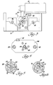
- a material injection assembly constructed in accordance with the instant invention is generally shown at 10.
- the assembly 10 includes a body member generally indicated at 12 defining a nozzle 13 for injecting material into a mold 14, as shown in FIGURES 1 and 2.
- the body member 12 includes a central channel 16 for conveying a first material, such as a plastic resin, through the nozzle 13.
- the body member 12 further includes a material supply channel 18 having an inlet 19 in communication with the central channel 16.
- the material supply channel 18 is also in communication with input mixers for supplying the resin material to the injection assembly 10.
- a purging material channel 20 has an inlet 21 in communication with the central channel 16.
- the purging material channel also communicates with a solvent source for selectively supplying a solvent to the subject assembly 10.
- the body member 12 further includes a debris channel 22 having an inlet 23 in communication with the central channel 16.
- the debris channel 22 functions to remove resin material and solvent from the assembly 10, as will be described below.
- the channels 18, 20 and 22 are bored into the body member 12, the entrance to the bores being plugged by threaded plug members, like plug 28 which plugs the bore between passages 22 and 16, as best shown in FIGURE 5.
- the channel 18 has a threaded inlet 24 for receiving a feed line.
- channel 20 has a threaded inlet 26.
- Ports 30 and 32 are passageways for the provision of lubrication to the body member.
- the body member 12 is slidably mounted on guide 34 which is provided with insulation 35 thereabout.
- a crossbar 36 provides additional support.
- the assembly is characterized by including internal purging means for closing the central channel 16 to the mold 14 while purging the central channel 16 of the resin material therein.
- resin material is flushed from the assembly 10 without having to go through the nozzle 13.
- This internal purging function is a significant improvement over the sloppy and inefficient methods of prior art assemblies wherein the mold is spread open from the nozzle and solvent is flushed through and out of the nozzle member.
- the internal purging means includes valve means generally indicated at 38, disposed within the central channel 16.
- the valve means 38 includes an elongated rod member 38 including first and second end portions 40 and 42, respectively, in sliding engagement with and conforming with the central channel 16.
- the rod member 38 further includes a middle or waist portion 44 which is smaller than the central channel 16. The rod member 38 is moveable relative to the body portion 12.
- the rod 38 has a purging position for establishing communication between the material supply channel 18 and the debris channel 22 and a post-purging position for establishing communication between the purging material supply channel 20 and the debris channel 22.
- a first actuator means consists of a pair of piston rods 48 and 50 driven by a pair of hydraulic cylinders 52 and 54, respectively. Piston rods 48 and 50 are connected to the crossbar 36 by bolts 31 which extend through bushings 33. The piston rods 48 and 50 selectively move the body member 12 between an inoperative position when the piston rods 48 and 50 are retracted wherein the rod member 38 is in the purging position and a second operative position when the piston rods 48 and 50 are extended wherein the rod member 38 is in the post-purging position.
- the first position is inoperative, since the assembly cannot supply resin to a mold when the body member 12 is in the retracted position. More specifically, a purging function is generally necessary to flush the material supply channel 18 with solvent to remove the remaining plastic resin material in between various runs or before a shutdown. In doing so, solvent is washed through the material supply channel 18.
- the body member 12 Prior to receiving the solvent, the body member 12 is moved to the first position (the hydraulic cylinders retract the pistons 48 and 50, thusly move the body member 12 towards the hydraulic cylinders 52 and 54) so that the middle portion 44 extends between inlets 19 and 23.
- the middle portion 44 of the rod member 38 allows flow between the material supply channel 18 and the debris channel 22.
- the solvent enters the material supply channel 18, flows through the central channel 16 about the middle portion 44 of the rod member 38 and exits through the debris channel 22.
- the resin material is flushed from the nozzle assembly without having to go through the mold 14.
- the body member 12 In order to prime the assembly for a new run, the body member 12 is again moved to the first position wherein the middle portion 44 extends between inlets 19 and 23. Since it is necessary to flush the solvent from entering the mold 14, the plastic resin material for the new run is allowed to flow through the material supply channel 18 and across the middle portion 44 of the rod member 38, thereby flushing the solvent out through the debris channel 22. The body member 12 is moved to the operational position and the material supply channel 18 is primed for injection of the plastic resin material into the mold 14. The remaining problem is that there is plastic resin material remaining in the debris channel 22 and there is sufficient heat from the mold 14 conducted through the assembly 10 to cure the resin material within the debris channel 12.
- solvent is injected to flow through the purging material supply channel 20, across the middle portion 44 of the rod member 38, and through the debris channel 22, thereby flushing the plastic resin material from the debris channel 22.
- This position of the assembly is illustrated in FIGURE 2.
- a post-purge function is performed wherein the assembly is primed for injection of the plastic resin material.
- Bracket members 45 and 47 are connected to the body member 12.
- An adjustable set screw 49 contacts a limit switch assembly, generally shown at 51.
- the adjustable stop engages a plunger in the limit switch assembly 51 to provide a signal indicating to the control system (not shown) that the body member 12 is in that position.
- the assembly 10 further includes second actuator means consisting of a piston 56 actuated by a hydraulic cylinder 58 for moving the rod member 38 between an extended position (solid line shown in FIGURES 1 and 2) wherein the first end portion 40 closes the material supply channel 18 to the central channel 16 and a retracted position (hatched line shown in FIGURES 1 and 2) wherein the material supply channel 18 is open to the central channel 16. T husly, the end portion 40 of the rod member 38 controls flow of resin material into the main channel 16 and the mold 14 communicating therewith.
- second actuator means consisting of a piston 56 actuated by a hydraulic cylinder 58 for moving the rod member 38 between an extended position (solid line shown in FIGURES 1 and 2) wherein the first end portion 40 closes the material supply channel 18 to the central channel 16 and a retracted position (hatched line shown in FIGURES 1 and 2) wherein the material supply channel 18 is open to the central channel 16. T husly, the end portion 40 of the rod member 38 controls flow of resin material into the main channel 16 and the mold
- the piston rod 56 includes an internally threaded female end portion.
- a connector member 60 interconnects the second end portion 42 of the rod member 38 to the piston rod 56 by providing a threaded male portion 62 thereof which is secured within the threaded female portion of the piston rod 56.
- Pin 59 prevents relative rotation between the piston rod 56 and connector 60.
- a housing 64 is threadedly secured to the connector 60 and engages the terminal portion of the end portion 42 of the rod member 38.
- Bracket 53 is secured between the connector 60 and piston rod 56.
- Bracket 55 is connected to bracket 53 and includes an adjustable screw 57 connected thereto. The screw 57 actuates a limit switch assembly, generally shown at 61, when the rod member 38 is in the extended position.
- the signal from the limit switch assembly 61 indicates to the control system that the rod member 38 is in the extended position.
- a rod member 65 is fixedly secured to the assembly support structure 71 by nut member 79.
- Bracket 53 slidably engages the rod member 65 whereby the rod member 65 prevents rotation of the brackets 53 and 55 ensuring consistent alignment of screw 57 with the limit switch 61.
- the nozzle 13 includes an outlet port 64 which is tapered or contoured to a predetermined shape.
- the shape of the outlet port 64 corresponds to the shape of the inlet port or wall of the mold 14.
- the first end portion 40 of the rod member 38 includes an end surface 66 which is shaped to the same predetermined shape and is coplanar with the outlet port 64 when the rod member 38 is in the extended position. In other words, when the body member 12 is in the operational position and the rod member 38 is in the extended position, the end surface 66 of the first end portion 40 of the valve means 38 is flush with the outlet port 64 of the nozzle 13.
- the instant invention further includes antirotation means for preventing rotation of the rod member 38. It is essential to prevent rotation of the rod member 38 to maintain the end surface 66 flush with the outlet port 64.
- the antirotation means includes a key member 68 as shown in FIGURE 4.
- the second end portion 42 of the rod member 38 includes a longitudinal portion thereof having a flat surface 69, as shown in FIGURES 2, 3 and 4.
- the flat surface of the key member 68 abuts the flat surface 69 of the second end portion 42 of the rod member 38 for allowing axial movement of the rod member 38 while preventing rotation thereof.
- the key member 68 maintains the angled or contoured end surface 66 flush with the tapered or contoured outlet port 64.
- other means can be utilized to prevent rotation of the rod member 38 in accordance with the instant invention.
- the body member 12 further includes a coolant supply channel 70.
- the channel 70 is bored into the body member 12, the bores being sealed by plug members 73.
- the coolant supply channel 70 extends substantially parallel to the central channel 16.
- the coolant supply channel 70 bifurcates about the central channel 16 proximal to the nozzle 13 into two channels 75 and 77 which are substantially perpendicular to said coolant supply channel 70, as shown in cross section in FIGURE 6.
- the channel 75 and 77 communicate with two coolant return channels 72 and 74, respectively, for returning the coolant for recirculation.
- the bifurcation 75, 77 is located in the portion above the body member 12 nearest to the mold 14.
- the bifurcation 75, 77 of the coolant channel 70 provides the greatest amount of cooling capacity at the portion nearest the portion of the assembly 10 which is exposed to the greatest heat.
- the subject material injection assembly 10 is mounted on the support structure 71 and the assembly 10 is connected to a mold 14 for the injection molding operation.
- a ring seal 74 is disposed about the nozzle 13 and positioned against the mold surface.
- the body member 12 Prior to receiving the purging material, the body member 12 is moved to the inoperative position so that the middle waist portion 44 of the rod member 38 allows flow between the material supply channel 18 and the debris channel 22. Flushing solvent enters through the material supply channel 18 and inlet 19 to the central channel 16, across the middle waist portion 44, and exits through the debris channel 22. Thusly, material is flushed from the assembly 10 without having to go through the mold 14 and without spreading open the nozzle 13 from the mold 14. In order to prime the assembly 10 for a new run, the body member 10 is moved to the inoperative retracted position.
- the material for the new run is allowed to flow through channel 18 and across the middle waist portion 44 of the rod member 38, thereby flushing the purging material out through the debris channel 22.
- the body member 12 is then actuated to move to the extended operative position and the assembly 10 is primed for injection of material into the mold 14.
- Purging material is injected to flow through purging material channel 20, across the middle waist portion 44, and through the debris channel 22, thereby flushing the material remaining within the debris channel 22 which otherwise would be set by the heat from the adjoining mold 14.
- the post purge function is performed.
Landscapes
- Engineering & Computer Science (AREA)
- Manufacturing & Machinery (AREA)
- Mechanical Engineering (AREA)
- Moulds For Moulding Plastics Or The Like (AREA)
- Injection Moulding Of Plastics Or The Like (AREA)
Priority Applications (1)
| Application Number | Priority Date | Filing Date | Title |
|---|---|---|---|
| AT82303621T ATE18154T1 (de) | 1981-07-27 | 1982-07-09 | Einspritzvorrichtung fuer kunststoffspritzgussformen. |
Applications Claiming Priority (2)
| Application Number | Priority Date | Filing Date | Title |
|---|---|---|---|
| US287112 | 1981-07-27 | ||
| US06/287,112 US4386899A (en) | 1981-07-27 | 1981-07-27 | Injector for plastic molds |
Publications (2)
| Publication Number | Publication Date |
|---|---|
| EP0072103A1 true EP0072103A1 (de) | 1983-02-16 |
| EP0072103B1 EP0072103B1 (de) | 1986-02-26 |
Family
ID=23101506
Family Applications (1)
| Application Number | Title | Priority Date | Filing Date |
|---|---|---|---|
| EP82303621A Expired EP0072103B1 (de) | 1981-07-27 | 1982-07-09 | Einspritzvorrichtung für Kunststoff-Spritzgussformen |
Country Status (6)
| Country | Link |
|---|---|
| US (1) | US4386899A (de) |
| EP (1) | EP0072103B1 (de) |
| JP (1) | JPS5824424A (de) |
| AT (1) | ATE18154T1 (de) |
| CA (1) | CA1179465A (de) |
| DE (1) | DE3269367D1 (de) |
Cited By (1)
| Publication number | Priority date | Publication date | Assignee | Title |
|---|---|---|---|---|
| EP0113222A3 (en) * | 1983-01-06 | 1985-12-18 | Ford Motor Company Limited | Back flush injection nozzle |
Families Citing this family (6)
| Publication number | Priority date | Publication date | Assignee | Title |
|---|---|---|---|---|
| US4898327A (en) * | 1988-08-22 | 1990-02-06 | Sealed Air Corporation | Injection system for foamable compositions |
| US5187001A (en) * | 1990-09-26 | 1993-02-16 | Gencorp Inc. | Resin transfer molding apparatus |
| US5186905A (en) * | 1991-07-16 | 1993-02-16 | Sealed Air Corporation | Cartridge port design for dispensing foam precursors |
| JP2612795B2 (ja) * | 1992-06-15 | 1997-05-21 | 世紀株式会社 | ランナーレス射出成形装置 |
| US5397230A (en) * | 1993-08-04 | 1995-03-14 | Gencorp Inc. | Vent apparatus for an injection mold |
| CN118124086B (zh) * | 2024-05-06 | 2024-07-09 | 恩格尔注塑机械(常州)有限公司 | 一种注塑机喷涂装置 |
Citations (6)
| Publication number | Priority date | Publication date | Assignee | Title |
|---|---|---|---|---|
| US2551439A (en) * | 1949-02-07 | 1951-05-01 | George J Kovacs | Method and apparatus for molding thermoplastic materials |
| US3247304A (en) * | 1961-10-17 | 1966-04-19 | Owens Illinois Glass Co | Method of and apparatus for making plastic articles |
| GB1211496A (en) * | 1968-02-23 | 1970-11-04 | Bayer Ag | Mould-closure cock for machines for the production of articles using highly reactive multi-component mixtures |
| USRE28721E (en) * | 1970-11-25 | 1976-02-24 | Farrell Patent Company | Time saver plastic draw-back valve assembly |
| US3975128A (en) * | 1973-05-29 | 1976-08-17 | Krauss-Maffei Aktiengesellschaft | System for filling a mold with reactive synthetic-resin components |
| US4260348A (en) * | 1979-10-12 | 1981-04-07 | Graham Theodore D | Sprue bushing for injection molding machine |
Family Cites Families (3)
| Publication number | Priority date | Publication date | Assignee | Title |
|---|---|---|---|---|
| GB1277030A (en) * | 1968-12-27 | 1972-06-07 | Harry Dudley Wright | Improvements in plastic moulding machines |
| FR2330528A1 (fr) * | 1975-11-06 | 1977-06-03 | Werner & Pfleiderer | Presse a injection a piston pour la fabrication de pieces de forme |
| US4260359A (en) * | 1978-12-21 | 1981-04-07 | Hooker Chemicals & Plastics Corp. | Apparatus for runnerless injection molding thermosetting materials |
-
1981
- 1981-07-27 US US06/287,112 patent/US4386899A/en not_active Expired - Lifetime
-
1982
- 1982-07-09 AT AT82303621T patent/ATE18154T1/de not_active IP Right Cessation
- 1982-07-09 EP EP82303621A patent/EP0072103B1/de not_active Expired
- 1982-07-09 DE DE8282303621T patent/DE3269367D1/de not_active Expired
- 1982-07-20 CA CA000407626A patent/CA1179465A/en not_active Expired
- 1982-07-27 JP JP57131073A patent/JPS5824424A/ja active Granted
Patent Citations (6)
| Publication number | Priority date | Publication date | Assignee | Title |
|---|---|---|---|---|
| US2551439A (en) * | 1949-02-07 | 1951-05-01 | George J Kovacs | Method and apparatus for molding thermoplastic materials |
| US3247304A (en) * | 1961-10-17 | 1966-04-19 | Owens Illinois Glass Co | Method of and apparatus for making plastic articles |
| GB1211496A (en) * | 1968-02-23 | 1970-11-04 | Bayer Ag | Mould-closure cock for machines for the production of articles using highly reactive multi-component mixtures |
| USRE28721E (en) * | 1970-11-25 | 1976-02-24 | Farrell Patent Company | Time saver plastic draw-back valve assembly |
| US3975128A (en) * | 1973-05-29 | 1976-08-17 | Krauss-Maffei Aktiengesellschaft | System for filling a mold with reactive synthetic-resin components |
| US4260348A (en) * | 1979-10-12 | 1981-04-07 | Graham Theodore D | Sprue bushing for injection molding machine |
Cited By (1)
| Publication number | Priority date | Publication date | Assignee | Title |
|---|---|---|---|---|
| EP0113222A3 (en) * | 1983-01-06 | 1985-12-18 | Ford Motor Company Limited | Back flush injection nozzle |
Also Published As
| Publication number | Publication date |
|---|---|
| DE3269367D1 (en) | 1986-04-03 |
| JPS5824424A (ja) | 1983-02-14 |
| EP0072103B1 (de) | 1986-02-26 |
| ATE18154T1 (de) | 1986-03-15 |
| CA1179465A (en) | 1984-12-18 |
| JPH0224203B2 (de) | 1990-05-28 |
| US4386899A (en) | 1983-06-07 |
Similar Documents
| Publication | Publication Date | Title |
|---|---|---|
| DE69323143T2 (de) | Buchse für Heisskanalverteiler | |
| US5200207A (en) | Hot runner system for coinjection | |
| US5187001A (en) | Resin transfer molding apparatus | |
| US4140238A (en) | Nozzle shut-off valve | |
| US4981426A (en) | Clamping mechanism in an injection molding machine | |
| DE69524797T2 (de) | Abdichtungsbüchse für Ventil im Spritzgiessen mit dünnem Kragenteil | |
| CH654521A5 (de) | Formschliesseinheit fuer kunststoff-spritzgiessmaschine. | |
| DE2940044A1 (de) | Verfahren zum spritzgiessen sowie eine spritzgusseinrichtung hierfuer | |
| US4386899A (en) | Injector for plastic molds | |
| US20050046083A1 (en) | Multi-position valve pin for an injection molding apparatus | |
| EP0462969A4 (de) | System und verfahren zur herstellung eines hohlförmigen rumpfes aus geschmolzenem harz durch spritzgiessen. | |
| US5851571A (en) | Needle valve nozzle for injection molds and valve needle | |
| US4740089A (en) | Movable-chamber mixing head | |
| US4443179A (en) | Rapid-action mold closer | |
| JPH0433248B2 (de) | ||
| US4420028A (en) | Lubrication system for a die casting machine | |
| US4407649A (en) | Injection molding machine | |
| US4913644A (en) | System for making a hollow-shaped body from molten resin by injection molding | |
| FI106973B (fi) | Ruiskutuslaitteisto iskumäntäpolttomoottorikoneen polttoaineen ruiskuttamiseksi | |
| DE112006003673T5 (de) | Plastifiziervorrichtung und Verfahren zur Steuerung derselben | |
| JP2755137B2 (ja) | 射出成形機のノズル装置 | |
| JPS62236717A (ja) | 射出成形機 | |
| EP1658169B1 (de) | Mehrpositionsventilnadel für eine spritzgiessvorrichtung und entsprechendes verfahren | |
| JPS6329531Y2 (de) | ||
| JPS6232817Y2 (de) |
Legal Events
| Date | Code | Title | Description |
|---|---|---|---|
| PUAI | Public reference made under article 153(3) epc to a published international application that has entered the european phase |
Free format text: ORIGINAL CODE: 0009012 |
|
| AK | Designated contracting states |
Designated state(s): AT BE CH DE FR GB IT LI LU NL SE |
|
| 17P | Request for examination filed |
Effective date: 19830811 |
|
| GRAA | (expected) grant |
Free format text: ORIGINAL CODE: 0009210 |
|
| AK | Designated contracting states |
Designated state(s): AT BE CH DE FR GB IT LI LU NL SE |
|
| PG25 | Lapsed in a contracting state [announced via postgrant information from national office to epo] |
Ref country code: NL Effective date: 19860226 Ref country code: IT Free format text: LAPSE BECAUSE OF FAILURE TO SUBMIT A TRANSLATION OF THE DESCRIPTION OR TO PAY THE FEE WITHIN THE PRESCRIBED TIME-LIMIT;WARNING: LAPSES OF ITALIAN PATENTS WITH EFFECTIVE DATE BEFORE 2007 MAY HAVE OCCURRED AT ANY TIME BEFORE 2007. THE CORRECT EFFECTIVE DATE MAY BE DIFFERENT FROM THE ONE RECORDED. Effective date: 19860226 Ref country code: BE Effective date: 19860226 Ref country code: AT Effective date: 19860226 |
|
| REF | Corresponds to: |
Ref document number: 18154 Country of ref document: AT Date of ref document: 19860315 Kind code of ref document: T |
|
| PG25 | Lapsed in a contracting state [announced via postgrant information from national office to epo] |
Ref country code: SE Effective date: 19860228 |
|
| REF | Corresponds to: |
Ref document number: 3269367 Country of ref document: DE Date of ref document: 19860403 |
|
| ET | Fr: translation filed | ||
| NLV1 | Nl: lapsed or annulled due to failure to fulfill the requirements of art. 29p and 29m of the patents act | ||
| PG25 | Lapsed in a contracting state [announced via postgrant information from national office to epo] |
Ref country code: LU Free format text: LAPSE BECAUSE OF NON-PAYMENT OF DUE FEES Effective date: 19860731 |
|
| PLBE | No opposition filed within time limit |
Free format text: ORIGINAL CODE: 0009261 |
|
| STAA | Information on the status of an ep patent application or granted ep patent |
Free format text: STATUS: NO OPPOSITION FILED WITHIN TIME LIMIT |
|
| 26N | No opposition filed | ||
| PGFP | Annual fee paid to national office [announced via postgrant information from national office to epo] |
Ref country code: GB Payment date: 19940706 Year of fee payment: 13 |
|
| PGFP | Annual fee paid to national office [announced via postgrant information from national office to epo] |
Ref country code: DE Payment date: 19940708 Year of fee payment: 13 |
|
| PGFP | Annual fee paid to national office [announced via postgrant information from national office to epo] |
Ref country code: FR Payment date: 19940711 Year of fee payment: 13 |
|
| PGFP | Annual fee paid to national office [announced via postgrant information from national office to epo] |
Ref country code: CH Payment date: 19940713 Year of fee payment: 13 |
|
| PG25 | Lapsed in a contracting state [announced via postgrant information from national office to epo] |
Ref country code: GB Effective date: 19950709 |
|
| PG25 | Lapsed in a contracting state [announced via postgrant information from national office to epo] |
Ref country code: LI Effective date: 19950731 Ref country code: CH Effective date: 19950731 |
|
| GBPC | Gb: european patent ceased through non-payment of renewal fee |
Effective date: 19950709 |
|
| REG | Reference to a national code |
Ref country code: CH Ref legal event code: PL |
|
| PG25 | Lapsed in a contracting state [announced via postgrant information from national office to epo] |
Ref country code: DE Effective date: 19960402 |
|
| PG25 | Lapsed in a contracting state [announced via postgrant information from national office to epo] |
Ref country code: FR Effective date: 19960430 |
|
| REG | Reference to a national code |
Ref country code: FR Ref legal event code: ST |
|
| REG | Reference to a national code |
Ref country code: FR Ref legal event code: ST |
|
| REG | Reference to a national code |
Ref country code: FR Ref legal event code: ST |