EP0072162B1 - Méthode et système de commande d'avance à l'allumage pour un moteur à combustion interne à plusieurs cylindres - Google Patents
Méthode et système de commande d'avance à l'allumage pour un moteur à combustion interne à plusieurs cylindres Download PDFInfo
- Publication number
- EP0072162B1 EP0072162B1 EP82304034A EP82304034A EP0072162B1 EP 0072162 B1 EP0072162 B1 EP 0072162B1 EP 82304034 A EP82304034 A EP 82304034A EP 82304034 A EP82304034 A EP 82304034A EP 0072162 B1 EP0072162 B1 EP 0072162B1
- Authority
- EP
- European Patent Office
- Prior art keywords
- ignition timings
- combination
- ignition
- engine
- timings
- Prior art date
- Legal status (The legal status is an assumption and is not a legal conclusion. Google has not performed a legal analysis and makes no representation as to the accuracy of the status listed.)
- Expired
Links
- 238000000034 method Methods 0.000 title claims description 18
- 238000002485 combustion reaction Methods 0.000 title claims description 8
- 238000013459 approach Methods 0.000 claims description 4
- 238000001514 detection method Methods 0.000 claims 1
- 238000012937 correction Methods 0.000 description 10
- 230000000694 effects Effects 0.000 description 5
- 230000001133 acceleration Effects 0.000 description 3
- 238000010586 diagram Methods 0.000 description 3
- 230000003247 decreasing effect Effects 0.000 description 2
- 239000000446 fuel Substances 0.000 description 2
- 230000008030 elimination Effects 0.000 description 1
- 238000003379 elimination reaction Methods 0.000 description 1
- 238000012986 modification Methods 0.000 description 1
- 230000004048 modification Effects 0.000 description 1
- 238000012545 processing Methods 0.000 description 1
- 230000004044 response Effects 0.000 description 1
- 238000006467 substitution reaction Methods 0.000 description 1
- 238000011144 upstream manufacturing Methods 0.000 description 1
Images


Classifications
-
- F—MECHANICAL ENGINEERING; LIGHTING; HEATING; WEAPONS; BLASTING
- F02—COMBUSTION ENGINES; HOT-GAS OR COMBUSTION-PRODUCT ENGINE PLANTS
- F02P—IGNITION, OTHER THAN COMPRESSION IGNITION, FOR INTERNAL-COMBUSTION ENGINES; TESTING OF IGNITION TIMING IN COMPRESSION-IGNITION ENGINES
- F02P5/00—Advancing or retarding ignition; Control therefor
- F02P5/04—Advancing or retarding ignition; Control therefor automatically, as a function of the working conditions of the engine or vehicle or of the atmospheric conditions
- F02P5/145—Advancing or retarding ignition; Control therefor automatically, as a function of the working conditions of the engine or vehicle or of the atmospheric conditions using electrical means
- F02P5/1455—Advancing or retarding ignition; Control therefor automatically, as a function of the working conditions of the engine or vehicle or of the atmospheric conditions using electrical means by using a second control of the closed loop type
-
- Y—GENERAL TAGGING OF NEW TECHNOLOGICAL DEVELOPMENTS; GENERAL TAGGING OF CROSS-SECTIONAL TECHNOLOGIES SPANNING OVER SEVERAL SECTIONS OF THE IPC; TECHNICAL SUBJECTS COVERED BY FORMER USPC CROSS-REFERENCE ART COLLECTIONS [XRACs] AND DIGESTS
- Y02—TECHNOLOGIES OR APPLICATIONS FOR MITIGATION OR ADAPTATION AGAINST CLIMATE CHANGE
- Y02T—CLIMATE CHANGE MITIGATION TECHNOLOGIES RELATED TO TRANSPORTATION
- Y02T10/00—Road transport of goods or passengers
- Y02T10/10—Internal combustion engine [ICE] based vehicles
- Y02T10/40—Engine management systems
Definitions
- the present invention relates to a method and system for optimum control of ignition timing in a multicylinder internal combustion engine so as to increase fuel consumption efficiency.
- Ignition timing of an internal combustion engine is generally an average value, determined according to engine running conditions such as an engine speed and intake pressure (or intake air flow), allowing maximum output and minimum fuel consumption.
- Multicylinder engines usually have the same average ignition timing applied to each cylinder. The ignition timing allowing maximum output differs, however, for each cylinder due to individual cylinder differences. Therefore, the above-mentioned average ignition timing is not always optimum, for any one cylinder. Application of the same average value to all the cylinders can therefore cause decreased output.
- the object of the present invention as claimed is a method and a system which ensures maximum output efficiency by application of the optimum ignition timing to each engine cylinder.
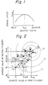
- Fig. 1 shows, there is a single ignition timing maximizing the engine speed. This optimal ignition timing is given as ⁇ opt and the maximum speed as N max . Optimum ignition timing ⁇ opt is normally different for each cylinder.
- the contour map shows, there is a single combination of ignition timings ⁇ 1opt and ⁇ 2opt where peak A of engine speed is attained. Operation of the engine under said combination of optimum ignition timings ⁇ 1opt and ⁇ 2opt produces maximum engine speed.
- the combination of ignition timings producing the maximum engine speed is obtained in accordance with the principle described below.
- an ignition timing of the first cylinder is designated as 8 1 and an ignition timing of the second cylinder is designated as 8 2 .
- This combination of ignition timings, point L, is considered to give an engine speed N 1 when an engine is operated thereunder.
- 8 1 and 8 2 are considered correction values, for the ignition timing, to be added to base ignition timing 8 s determined in accordance with such engine running conditions as amount of intake air (or intake air pressure) and engine speed.
- the origin in Fig. 2 in terms of ignition timing, is not zero, but 8g.
- the actual ignition timing value therefore, is 8 1 or 8 2 plus 8 g.
- the engine is then operated under the combination of ignition timings of point H, which is slightly different from point L, for example, having an ignition timing of the first cylinder slightly larger by ⁇ 1 but with the same ignition timing of the second cylinder ( ⁇ 1 + ⁇ 1 , 8 2 ).
- the engine speed at this time is designated as N 2 .
- the engine is then further operated under the combination of ignition timings of point S, for example, with an ignition timing of the second cylinder slightly larger by ⁇ 2 but with the same ignition timing of the first cylinder (8 1 , ⁇ 2 + ⁇ 2 ).
- the combinations of ignition timings of the two-cylinder engine are as shown in the following table.
- the average values ⁇ of each cylinder in these three combinations of ignition timing are calculated, the average value ⁇ for the first cylinder being ⁇ 1 + ⁇ /3 and for the second cylinder being ⁇ 2 + ⁇ /3.
- the combination of ignition timings giving the lowest engine speed is determined. In the case of Fig. 2, this would be the combination of ignition timings 8 1 and ⁇ 3 of point L, giving engine speed N 1 0
- a new point R 1 is set on the line running through average value ⁇ and combination of ignition timings point L, where the lowest engine speed is obtained, away from the point of average value ⁇ in the direction opposite to point L, i.e., in the direction increasing the engine speed.
- the combination of ignition timings ( ⁇ 1 ', 6 2 ') at this point R, is then calculated.
- the engine is operated under this combination of ignition timings and engine speed N 4 is obtained.
- Engine speed N 4 is substituted for the lowest engine speed N 1 .
- the three engine speeds N 2 , N 3 , and N 4 are compared, and point H of the next lowest engine speed, in the case of Fig. 2, N 2 , is determined. Then, the average value 8' of the three combinations of ignition timings is calculated.
- Another new point R 2 is set on the line running through average valuer and point H of the next lowest engine speed away from the point of average value ⁇ ' in the direction opposite to point H, i.e., in the direction increasing the engine speed.
- the process is repeated to set prints R 1 ⁇ R 2 ⁇ R 3 ⁇ R 4 ⁇ R 5 ⁇ R 6 ⁇ R 7 ⁇ R 8 and correct the combinations of ignition values in the direction increasing the engine speed, thereby enabling the engine speed peak A to be approached.
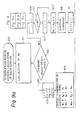
- Figure 3 shows the method for setting new points R with respect to the three basic points H, S, and L.
- Average value 8 is obtained by the following vector equation: New points R( ⁇ new ) to be substituted for point L( ⁇ min ) is obtained by the following equation: where, a: constant
- the above-mentioned explanation was directed to a two-cylinder internal combustion engine for simplicity.
- the present invention can, however, be applied to engines having large numbers of cylinders for controlling ignition timings of each cylinder and maximizing engine rotational speed.
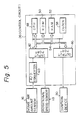
- reference numeral 10 denotes a body of an internal combustion engine provided with four cylinders #1, #2, #3, and #4. Intake air is introduced to each cylinder from the intake manifold 12.
- the throttle valve 14 controls the amount of intake air.
- An air flow meter 16 is arranged upstream of a throttle valve 14 for measuring the amount of intake air.
- the amount of intake air can alternatively be measured by the pressure in the intake pipe.
- Reference numeral 18 denotes a engine speed sensor for producing an electric signal in response to the engine speed. As the engine speed sensor 18, a conventional crank angle sensor may be used for producing pulse signals at every predetermined engine crank angle.
- Reference numeral 20 denotes an ignition device comprising an electronic ignitor, a distributor, and an ignition coil (not shown).
- the ignition device 20 is connected to spark plug electrodes 21-1, 21-2, 21-3, and 21-4 via electric lines 22.
- the ignition control circuit 26 operates to produce operational signals directed to the ignition device 20.
- the ignition control circuit 26 includes a computer programmed to effect the routine described later.
- the intake air flow sensor 16 and rotational speed sensor 18 are connected to the ignition control circuit 26 via line 30 and 32, respectively.
- the ignition control circuit 26 operates to calculate the ignition timing based on the intake air amount as well as the engine speed.
- an input port 42 is adapted for receiving signals from the intake air amount sensor 16 and rotational speed sensor 18.
- Analog to digital (A/D) convertor 40 operates to change the analog signal from the intake air sensor 16 to a digital signal.
- An output port 46 operates as a signal gate to the ignition device 20.
- the input port 42 and output port 46 are connected via a bus 54 to central processing unit (CPU) 48, read only memory (ROM) 50 and random access memory (RAM) 50 which are elements of a microcomputer system. Signals are transmitted between these parts synchronously with clock pulses from a clock pulse generator 58.
- CPU central processing unit
- ROM read only memory
- RAM random access memory
- the ignition control circuit 26 is programmed to produce the optimal ignition timing for each cylinder according to the principle of the present invention.
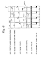
- the time chart effected by this program as applied to a two-cylinder engine, is schematically illustrated in Fig. 6.
- first step S 1 of the calculation the ignition timings of the cylinders are designated 8 1 and 8 2 , respectively as shown by (a) and (b) in Fig. 6.
- Operating the engine under these conditions causes a change in the engine speed, as shown by (c), and produces ignition signals, as shown by (d).
- the clock pulses between predetermined ignition, signals C fo to C fend near the end of first step S 1 are taken in and counted, as shown in (e) and (f).
- the number of clock pulses located between ignition signals C fo and C tond is considered representative of the engine rotational speed N 1 obtained at first step S 1 .
- step S 2 the ignition timing of the first cylinder is increased to ⁇ 1 + ⁇ while the ignition timing of the second cylinder is maintained at ⁇ 2 .
- the engine is operated for the predetermined number of ignition signals and engine speed N 2 is measured as the number of clock pulses between ignition signals C fo and C fend .
- step S 3 the ignition timing of the first cylinder is decreased to ⁇ 1 while the ignition timing of the second cylinder is increased to ⁇ 2 + ⁇ .
- Engine speed N 3 is measured in a similar fashion.
- the ignition timings of the first and second cylinders are then set to ⁇ 1 ' and 8 2 ', respectively.
- the new combination of ignition timings 8 1 ' and 8 2 ' is obtained by first determining the average value ⁇ of the combinations of ignition timings, determining the point of the combination of ignition timings 8 min giving the lowest engine speed, then calculatir.g by formula (2) a new point R of a combination of ignition timings 8 1 ' and ⁇ 2 ' located away from average value ⁇ in the direction opposite to the point of the lowest engine speed.
- engine speed N 4 is measured as the number of clock pulses during operation of the engine by the predetermined number of ignition signals.
- Fourth step S 4 is continuously repeated with the new combinations of ignition timings being continuously substituted for the combinations of ignition timings of each previous step giving the lowest engine speed.
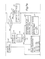
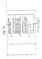
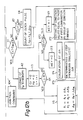
- the program for obtaining the time chart shown in Fig. 6 will be described by the flow chart, shown in Fig. 7.
- the program enters into the interruption routine at a point 100 for calculating the ignition timing.
- base ignition timing 8 s is calculated from the amount of intake air (or intake air pressure) detected by intake air amount sensor 16 (or intake air pressure sensor) and the engine speed detected by the speed sensor 18.
- ROM 50 is provided with a basic ignition timing map with respect to combinations intake air amounts and engine speeds. By using this memorized map, basic ignition timing ⁇ B corresponding to the combination of the detected intake air amount and engine speed is calculated.
- the actual ignition timings for the cylinders are obtained by adding 8 1 , ⁇ 2 ... ⁇ M to the basic ⁇ B ignition timing obtained at point 101. Then, the program proceeds to point 104'where CPU 48 produces a signal via the output port 46 to operate the ignition device 20, causing ignition at ignition timings H 1 , H 2 ...H M for each engine cylinder. The program then returns to the main routine at point 105.
- a counter J which is clear at every number of cylinders is incremented by 1.
- J it is judged whether or not J is larger than the number M of cylinder. If J is larger than M, the program proceeds to a point 107' to reset the counter to 1. If J is not larger than M, the program proceeds to a point 107".
- the ignition timings for the cylinders HJ are calculated.
- the program proceeds to a point 118.
- the clock counter is incremented by ⁇ np, corresponding to the number of clock pulses between two adjacent ignition signals.
- the program proceeds to the point 112, where the number of clock pulses counted by the clock pulse counter is stored in RAM 52. This np value corresponds to engine speed N, in step S 1 .
- the ignition counter and clock pulse counter are reset to 0, while the step counter is incremented by 1.
- judgement is made whether or not i ⁇ M. Since i is equal to 1, the result of the judgement at point 114 is Yes.
- the program then proceeds to a point 115 to determine the combination of ignition timings at point H (in Fig. 1). This corresponds to step S 2 of Fig. 6.
- the correction values of the cylinders are calculated by the following equations:
- the program then returns to the main routine at point 105.
- a value of ⁇ 21 other than 0 can be employed.
- the interruption routine again enters into calculation at a point 100 to detect the number of clock pulses between ignition signal C fo and C fend as engine speed N z in second step S 2 .
- the result is stored in the RAM 52 at the point 112.
- the ignition counter and clock pulse counter are reset and the step counter is incremented by 1.
- the number of clock pulses np is calculated as the engine speed N 3 of step S 3 in similar way by effecting the routine below the point 106, and is stored in the RAM 52 at the point 112.
- the first judgement at the point 114 is "No".
- the program proceeds to a point 120 to determine the point L in Fig. 2 for attaining the lowest engine speed.
- new ignition timing ⁇ new obtained at point 123 is substituted for ignition timing ⁇ min providing the lowest rotational speed.
- new ignition timings ⁇ new1 , ⁇ new2 ..., ⁇ newM are set as the correction values ⁇ 1 , ⁇ 2 . ⁇ , 8 M .
- step S 4 in Fig. 6 at the next interruption is effected to enter the routine of 106, 107, 107', 170", 108, 110, 111, 117, and 118 in Fig. 7 so as to measure engine speed N 4 .
- the program then proceeds to the points 120, 121, 122, 123, and 124, to calculate the average ignition timing value ⁇ ' in points S, H, and R 1 in Fig. 2; to determine new point R 2 where the engine speed is increased, to calculate the cylinder components of the ignition timing at point R 2 , and to calculate the correction values of ignition timing. This procedure is repeated to obtain peak A of the engine speed.
- the engine speed obtained in the new combination of ignition timings by formula (2) may have a value equal to the lowest engine speed obtained in the previous combination.
- Fig. 8 showing an enlarged view of the position near engine speed peak A in the contour map three points for obtaining the new point are indicated by R x , Ry, and R z .
- new point R x ' obtained by calculating formula (2) has engine speed N x ' equal to the lowest value (N x ) obtained at point R x .
- the new combination of ignition timings only moves between point R x and R x ' (so-called hunting effect), and the optimum combination of ignition timings providing peak A of the calculation cannot be obtained.
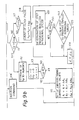
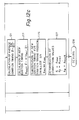
- FIG. 9 A program attaining such a principle is shown in the flow chart of Fig. 9. Points of the program in Fig. 9 having the same numbers as Fig. 7 correspond to those in Fig. 7. The program of Fig. 9 is therefore mainly explained with regard to points which differ from Fig. 7.
- a flag KEY is a flag which is set at a point 152, when the new combination of ignition timings is determined at point 124.
- the program proceeds to a point 153 where judgement is made whether or not the new combination of ignition timings will produce the lowest engine speed. If the judgement at the point 153 is "No", the program proceeds to the point 154, where a is set to a o , which is equal to the preceding value.
- ⁇ new ⁇ - ⁇ ( ⁇ min - ⁇ )
- the third embodiment which will be described hereinafter, is directed to the elimination of such other influences.
- the combinations of ignition timings in the case of two cylinders may be, for example, determined as shown by the following table.
- the average value ⁇ for the first and second cylinders therefore, is ⁇ 1 + ⁇ /4 and ⁇ 2 + ⁇ /4, respectively.
- the engine is once more operated at the first combination of ignition timings 8 1 and 8 2 .
- Any difference between engine speed N 1 ' obtained at this repeated first combination of ignition timings and engine speed N 1 obtained at the ignition timings ⁇ 1 and ⁇ 2 is regarded as an influence on the engine speed by engine running conditions other than ignition timing, such as acceleration pedal operation. If it is assumed that the engine speed linearly increases from N 1 to N 1 ' between the first and the last steps of the operation, the effect of the acceleration pedal operation on the engine speed obtained at steps S 1 and S 3 (other than the first and the last steps S 1 and S 4 ) can be calculated by interpolation. This can be used to correct the engine speed data and precisely calculate the combination of ignition timings producing the lowest engine speed only by the effect of ignition timing.
- a new combination of ignition timings is substituted, in the combinations of ignition timings, for the combination of ignition timings producing the lowest engine speed. Repeated substitution in subsequent steps enables the optimum combination of ignition timings producing the largest engine speed to be approached.
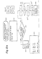
- FIG. 10 each illustrates the change of engine speed in a four-cylinder engine in adjacent three group combinations of ignition timings.
- first group (a) the engine is successively operated by combinations of ignition timings 1 through 5 (the number of combinations being equal to the number of engine cylinders plus 1) to obtain engine speed N 1 through N s at each step, and is then operated at a combination of ignition timings 1' equal to that of the first combination 1 to obtain engine speed N 1 ' at the last steps.
- Distances ⁇ N 2 , ⁇ N 3 , and AN 4 of the points of the engine speed at combinations 2, 3, 4, and 5 from a line connecting the points and ' of the engine speed of the same combination of ignition timings are calculated.
- Figure 11 shows a method for calculating the distance AN by interpolation.
- Such distance AN is calculated by the following equation: Since the engine speed linearly increases to N 1 ' from N 1 , such distances ⁇ N 2 , ⁇ N 3 , ⁇ N 4 , and ⁇ N 5 are considered influences on the engine speed by the change of ignition timing. Thus, the combination of ignition timings, for example 3, producing the smallest value of distance, ⁇ N 3 should be considered as the combination of ignition timings producing the lowest engine speed. Thus, a point 3' of the new combination of ignition timings is calculated by the formula: and is operated at point 3' to produce the smallest value of distance, ⁇ N 3 .
- a new group of combinations of ignition timings comprised of points 2, 4, 5, 1', and 3' in Fig. 10b is obtained.
- the engine is operated at combination of ignition timings point 2', which is equal to that of first point 2.
- combination of ignition timings points to produce the smallest value of distance, ⁇ N 5 ' is calculated.
- New point 5' obtained by the formula is substituted for point 5 and is operated to obtain the engine speed at the point.
- a new group of combinations of ignition timings comprised of 4, 1', 3', 2', and 5' is introduced as shown in Fig. 10c.
- the engine is operated at combination of ignition timings point 4' which is equal to that of first point 4 in this group.
- a new point 1" producing the smallest distance, which is replaced by 1' is determined.
- the result judgement at the point 114 is "Yes".
- the program proceeds to a point 170 where judgement is made whether or not flag KEY' is 0.
- KEY' is 0, the program proceeds to a point 171 to set flag KEY'.
- correction values of the ignition timing are determined equal to the correction values of the ignition timing of the first combination in this group of combinations of ignition timings (in the example in Fig. 10c, the combination of ignition timings at point 1).
- the engine is once more operated at this combination of ignition timings by effecting the points 106, 107, 107', 107", 108, 111, 117, 118 and 112 to obtain an engine speed, for example N' in Fig. 10c.
- the program proceeds to a point 173 to clear flag KEY' and then to a point 174 to calculate the distance as the change of engine speed ⁇ N.
- the combination of ignition timings producing the smallest distance ( ⁇ N 3 in Fig. 10a) is determined.
- average ignition timing value ⁇ is calculated.
- new combination of, ignition timings ⁇ new is calculated, as in Figs. 7 and 9.
- the new combination of ignition timings is substituted for the combination of ignition timings producing the smallest ⁇ N.
Landscapes
- Engineering & Computer Science (AREA)
- Chemical & Material Sciences (AREA)
- Combustion & Propulsion (AREA)
- Mechanical Engineering (AREA)
- General Engineering & Computer Science (AREA)
- Electrical Control Of Ignition Timing (AREA)
Claims (14)
Applications Claiming Priority (6)
| Application Number | Priority Date | Filing Date | Title |
|---|---|---|---|
| JP120026/81 | 1981-08-01 | ||
| JP56120026A JPS5823273A (ja) | 1981-08-01 | 1981-08-01 | 多気筒内燃機関の点火時期制御方法 |
| JP142004/81 | 1981-09-09 | ||
| JP56142004A JPS5844270A (ja) | 1981-09-09 | 1981-09-09 | 多気筒内燃機関の点火時期制御方法 |
| JP56144435A JPS5847159A (ja) | 1981-09-11 | 1981-09-11 | 多気筒内燃機関の点火時期制御方法 |
| JP144435/81 | 1981-09-11 |
Publications (4)
| Publication Number | Publication Date |
|---|---|
| EP0072162A2 EP0072162A2 (fr) | 1983-02-16 |
| EP0072162A3 EP0072162A3 (en) | 1983-08-17 |
| EP0072162B1 true EP0072162B1 (fr) | 1986-01-29 |
| EP0072162B2 EP0072162B2 (fr) | 1993-04-21 |
Family
ID=27313958
Family Applications (1)
| Application Number | Title | Priority Date | Filing Date |
|---|---|---|---|
| EP82304034A Expired - Lifetime EP0072162B2 (fr) | 1981-08-01 | 1982-07-30 | Méthode et système de commande d'avance à l'allumage pour un moteur à combustion interne à plusieurs cylindres |
Country Status (3)
| Country | Link |
|---|---|
| US (1) | US4432322A (fr) |
| EP (1) | EP0072162B2 (fr) |
| DE (1) | DE3268810D1 (fr) |
Families Citing this family (4)
| Publication number | Priority date | Publication date | Assignee | Title |
|---|---|---|---|---|
| JPH0660619B2 (ja) * | 1983-11-15 | 1994-08-10 | 日本電装株式会社 | 内燃機関用点火時期制御装置 |
| DE3408223A1 (de) * | 1984-02-01 | 1985-08-01 | Robert Bosch Gmbh, 7000 Stuttgart | Steuer- und regelverfahren fuer die betriebskenngroessen einer brennkraftmaschine |
| DE3403394A1 (de) * | 1984-02-01 | 1985-08-01 | Robert Bosch Gmbh, 7000 Stuttgart | Kraftstoff-luft-gemischzumesssystem fuer eine brennkraftmaschine |
| JPH0612093B2 (ja) * | 1985-02-19 | 1994-02-16 | 日本電装株式会社 | 内燃機関制御装置 |
Family Cites Families (13)
| Publication number | Priority date | Publication date | Assignee | Title |
|---|---|---|---|---|
| US4257373A (en) * | 1973-02-28 | 1981-03-24 | John A. McDougal | Internal combustion engine ignition system |
| US4054111A (en) * | 1976-07-19 | 1977-10-18 | General Motors Corporation | Internal combustion engine electronic ignition spark timing system modulated by cylinder combustion pressure |
| DE2633617C2 (de) * | 1976-07-27 | 1986-09-25 | Robert Bosch Gmbh, 7000 Stuttgart | Verfahren und Vorrichtung zur Bestimmung von Einstellgrößen bei einer Brennkraftmaschine, insbesondere der Dauer von Kraftstoffeinspritzimpulsen, des Zündwinkels, der Abgasrückführrate |
| JPS53137344A (en) * | 1977-04-14 | 1978-11-30 | Nippon Soken Inc | Internal combustion engine ignition time adjustor |
| US4207847A (en) * | 1977-05-11 | 1980-06-17 | Nippon Soken, Inc. | Electronic ignition control apparatus |
| US4240388A (en) * | 1977-09-19 | 1980-12-23 | Nippondenso Co., Ltd. | Method for controlling timing of spark ignition for an internal combustion engine |
| JPS6024310B2 (ja) * | 1977-12-16 | 1985-06-12 | 株式会社デンソー | 内燃機関用点火時期制御装置 |
| JPS557978A (en) * | 1978-07-04 | 1980-01-21 | Nippon Soken Inc | Ignition timing control system for internal combustion engine |
| US4234850A (en) * | 1979-01-08 | 1980-11-18 | Optimizer Control Corporation | Firing time control circuit |
| US4243007A (en) * | 1979-03-26 | 1981-01-06 | Shell Oil Company | Selective ignition timing |
| JPS56113049A (en) * | 1980-02-12 | 1981-09-05 | Nissan Motor Co Ltd | Ignition timing control method |
| DE3006633A1 (de) * | 1980-02-22 | 1981-08-27 | Robert Bosch Gmbh, 7000 Stuttgart | Zuendanlage fuer brennkraftmaschinen |
| US4368705A (en) * | 1981-03-03 | 1983-01-18 | Caterpillar Tractor Co. | Engine control system |
-
1982
- 1982-07-30 DE DE8282304034T patent/DE3268810D1/de not_active Expired
- 1982-07-30 EP EP82304034A patent/EP0072162B2/fr not_active Expired - Lifetime
- 1982-07-30 US US06/403,816 patent/US4432322A/en not_active Expired - Lifetime
Also Published As
| Publication number | Publication date |
|---|---|
| EP0072162A3 (en) | 1983-08-17 |
| US4432322A (en) | 1984-02-21 |
| DE3268810D1 (en) | 1986-03-13 |
| EP0072162B2 (fr) | 1993-04-21 |
| EP0072162A2 (fr) | 1983-02-16 |
Similar Documents
| Publication | Publication Date | Title |
|---|---|---|
| US4711212A (en) | Anti-knocking in internal combustion engine | |
| US5021960A (en) | Combustion fault detection apparatus and control system for internal combustion engine | |
| US4797828A (en) | Electronic control system for internal combustion engines | |
| US4449501A (en) | Device for adjusting engine timing | |
| JPS639679A (ja) | 内燃機関の点火時期制御方法 | |
| US4448171A (en) | Method and apparatus for optimum control of internal combustion engines | |
| US4191144A (en) | Method for controlling ignition timing in an internal combustion engine | |
| GB2176015A (en) | Detecting abnormality in crank angle signal of internal combustion engines | |
| US5493901A (en) | Combustion state-detecting system for internal combustion engines | |
| EP0203576B1 (fr) | Méthode de commande de l'avance à l'allumage pour moteur à combustion interne | |
| US4996959A (en) | Ignition timing control system for automotive engine | |
| KR930008806B1 (ko) | 엔진의 점화시기 제어장치 | |
| EP0733890B1 (fr) | Appareil de diagnose de raté d'allumage des moteurs multi-cylindres à combustion | |
| EP0115807A2 (fr) | Méthode de discrimination des pressions de combustion pour moteur à combustion interne | |
| US4711213A (en) | Knock control system for internal combustion engines | |
| US5471869A (en) | Combustion state-detecting system for internal combustion engines | |
| US4269155A (en) | Ignition timing control system for internal combustion engines | |
| EP0072162B1 (fr) | Méthode et système de commande d'avance à l'allumage pour un moteur à combustion interne à plusieurs cylindres | |
| GB2237388A (en) | System for detecting combustion condition of an internal combustion engine | |
| EP0183265B1 (fr) | Appareil pour la détection de pression dans une conduite d'aspiration | |
| US5571958A (en) | Apparatus and method for detecting misfire in an internal combustion engine | |
| US4467764A (en) | Method and apparatus for controlling ignition timing in a multicylinder internal combustion engine | |
| US5222394A (en) | System for detecting combustion condition of an internal combustion engine | |
| US4548178A (en) | Method and apparatus for controlling the air-fuel ratio in an internal-combustion engine | |
| EP0162470A2 (fr) | Méthode de commande de l'alimentation en carburant d'un moteur à combustion interne |
Legal Events
| Date | Code | Title | Description |
|---|---|---|---|
| PUAI | Public reference made under article 153(3) epc to a published international application that has entered the european phase |
Free format text: ORIGINAL CODE: 0009012 |
|
| AK | Designated contracting states |
Designated state(s): DE FR GB |
|
| PUAL | Search report despatched |
Free format text: ORIGINAL CODE: 0009013 |
|
| AK | Designated contracting states |
Designated state(s): DE FR GB |
|
| 17P | Request for examination filed |
Effective date: 19830815 |
|
| GRAA | (expected) grant |
Free format text: ORIGINAL CODE: 0009210 |
|
| AK | Designated contracting states |
Designated state(s): DE FR GB |
|
| REF | Corresponds to: |
Ref document number: 3268810 Country of ref document: DE Date of ref document: 19860313 |
|
| ET | Fr: translation filed | ||
| PLBI | Opposition filed |
Free format text: ORIGINAL CODE: 0009260 |
|
| PLBI | Opposition filed |
Free format text: ORIGINAL CODE: 0009260 |
|
| 26 | Opposition filed |
Opponent name: ROBERT BOSCH GMBH Effective date: 19861027 |
|
| 26 | Opposition filed |
Opponent name: SIEMENS AKTIENGESELLSCHAFT, BERLIN UND MUENCHEN Effective date: 19861029 |
|
| REG | Reference to a national code |
Ref country code: GB Ref legal event code: 746 |
|
| REG | Reference to a national code |
Ref country code: FR Ref legal event code: DL |
|
| PUAH | Patent maintained in amended form |
Free format text: ORIGINAL CODE: 0009272 |
|
| STAA | Information on the status of an ep patent application or granted ep patent |
Free format text: STATUS: PATENT MAINTAINED AS AMENDED |
|
| 27A | Patent maintained in amended form |
Effective date: 19930421 |
|
| AK | Designated contracting states |
Kind code of ref document: B2 Designated state(s): DE FR GB |
|
| ET3 | Fr: translation filed ** decision concerning opposition | ||
| APAC | Appeal dossier modified |
Free format text: ORIGINAL CODE: EPIDOS NOAPO |
|
| APAC | Appeal dossier modified |
Free format text: ORIGINAL CODE: EPIDOS NOAPO |
|
| PGFP | Annual fee paid to national office [announced via postgrant information from national office to epo] |
Ref country code: FR Payment date: 19980709 Year of fee payment: 17 |
|
| PGFP | Annual fee paid to national office [announced via postgrant information from national office to epo] |
Ref country code: GB Payment date: 19980721 Year of fee payment: 17 |
|
| PGFP | Annual fee paid to national office [announced via postgrant information from national office to epo] |
Ref country code: DE Payment date: 19980810 Year of fee payment: 17 |
|
| PG25 | Lapsed in a contracting state [announced via postgrant information from national office to epo] |
Ref country code: GB Free format text: LAPSE BECAUSE OF NON-PAYMENT OF DUE FEES Effective date: 19990730 |
|
| PG25 | Lapsed in a contracting state [announced via postgrant information from national office to epo] |
Ref country code: FR Free format text: THE PATENT HAS BEEN ANNULLED BY A DECISION OF A NATIONAL AUTHORITY Effective date: 19990731 |
|
| GBPC | Gb: european patent ceased through non-payment of renewal fee |
Effective date: 19990730 |
|
| PG25 | Lapsed in a contracting state [announced via postgrant information from national office to epo] |
Ref country code: DE Free format text: LAPSE BECAUSE OF NON-PAYMENT OF DUE FEES Effective date: 20000503 |
|
| REG | Reference to a national code |
Ref country code: FR Ref legal event code: ST |
|
| APAH | Appeal reference modified |
Free format text: ORIGINAL CODE: EPIDOSCREFNO |