EP0072768A2 - Kraftfahrzeugrad mit Druckmesser - Google Patents
Kraftfahrzeugrad mit Druckmesser Download PDFInfo
- Publication number
- EP0072768A2 EP0072768A2 EP82430020A EP82430020A EP0072768A2 EP 0072768 A2 EP0072768 A2 EP 0072768A2 EP 82430020 A EP82430020 A EP 82430020A EP 82430020 A EP82430020 A EP 82430020A EP 0072768 A2 EP0072768 A2 EP 0072768A2
- Authority
- EP
- European Patent Office
- Prior art keywords
- wheel
- pressure gauge
- pressure
- valve
- pipe
- Prior art date
- Legal status (The legal status is an assumption and is not a legal conclusion. Google has not performed a legal analysis and makes no representation as to the accuracy of the status listed.)
- Granted
Links
Images

Classifications
-
- B—PERFORMING OPERATIONS; TRANSPORTING
- B60—VEHICLES IN GENERAL
- B60C—VEHICLE TYRES; TYRE INFLATION; TYRE CHANGING; CONNECTING VALVES TO INFLATABLE ELASTIC BODIES IN GENERAL; DEVICES OR ARRANGEMENTS RELATED TO TYRES
- B60C23/00—Devices for measuring, signalling, controlling, or distributing tyre pressure or temperature, specially adapted for mounting on vehicles; Arrangement of tyre inflating devices on vehicles, e.g. of pumps or of tanks; Tyre cooling arrangements
- B60C23/02—Signalling devices actuated by tyre pressure
- B60C23/04—Signalling devices actuated by tyre pressure mounted on the wheel or tyre
- B60C23/0491—Constructional details of means for attaching the control device
- B60C23/0496—Valve stem attachments positioned outside of the tyre chamber
-
- B—PERFORMING OPERATIONS; TRANSPORTING
- B60—VEHICLES IN GENERAL
- B60C—VEHICLE TYRES; TYRE INFLATION; TYRE CHANGING; CONNECTING VALVES TO INFLATABLE ELASTIC BODIES IN GENERAL; DEVICES OR ARRANGEMENTS RELATED TO TYRES
- B60C23/00—Devices for measuring, signalling, controlling, or distributing tyre pressure or temperature, specially adapted for mounting on vehicles; Arrangement of tyre inflating devices on vehicles, e.g. of pumps or of tanks; Tyre cooling arrangements
- B60C23/02—Signalling devices actuated by tyre pressure
-
- B—PERFORMING OPERATIONS; TRANSPORTING
- B60—VEHICLES IN GENERAL
- B60C—VEHICLE TYRES; TYRE INFLATION; TYRE CHANGING; CONNECTING VALVES TO INFLATABLE ELASTIC BODIES IN GENERAL; DEVICES OR ARRANGEMENTS RELATED TO TYRES
- B60C23/00—Devices for measuring, signalling, controlling, or distributing tyre pressure or temperature, specially adapted for mounting on vehicles; Arrangement of tyre inflating devices on vehicles, e.g. of pumps or of tanks; Tyre cooling arrangements
- B60C23/02—Signalling devices actuated by tyre pressure
- B60C23/04—Signalling devices actuated by tyre pressure mounted on the wheel or tyre
Definitions
- the present invention relates to pressure wheels for motor vehicles.
- the object of the present invention is to allow permanent, precise verification without any manipulation of the pressure prevailing in each of the tires of the vehicle in order to allow drivers to achieve both energy savings and increase their safety.
- Manometric devices have been designed, in particular on heavy goods vehicles, allowing the lighting of an electrical warning light on the dashboard when the pressure drops in a wheel below a minimum.
- the transmission of this signal involved rotating electrical contacts between the moving wheel and the chassis, causing many nuisance alarms and the system is no longer used.
- Pressure sensors are also known, coupled to tiny radio transmitters fixed on each valve, and transmitting by electromagnetic waves to a receiver located on the chassis of the vehicle, the state of the pressures in each tire.
- these devices protrude from the rim-tire gauge and are therefore subject to receiving shocks against the curbs of the sidewalks during the rotation of the wheels.
- the first condition is easily fulfilled.
- the second seems incompatible with the third and the fourth because a metal membrane device, of large dimensions, therefore heavy, cannot be fixed permanently to a valve. Its presence would result in a significant imbalance, detrimental to the proper static and dynamic balancing of the wheel.
- the objective of the present invention is to provide means for checking the inflation pressure of a tire which fulfills all these conditions.
- the pressure gauge comprises a transparent disc, carrying several colored sectors and capable of being moved in rotation in order to assume a determined angular position.
- the pressure gauge is of the type comprising a Bourdon tube.
- the invention results in new vehicle wheels, each equipped with a pressure gauge allowing easy reading without the observer having to bend down, and allowing the immediate comparison of the pressure prevailing in each envelope with respect to the pressure of use recommended by the tire manufacturer, giving the user the possibility of quantitatively assessing whether the underpressure or overpressure prevailing in the tire is acceptable or not.
- the position of the pressure gauge in the center of the wheel has many advantages.
- a bulky device inevitably protruding from the rim-tire gauge, was penalized in its longevity because it was likely to violently strike the curbs of the sidewalks when moving the vehicle.
- a heavy device prohibited good static and dynamic balancing of the wheel.
- the position of the pressure gauge in the center of the wheel makes it possible to keep a bulky device while being sheltered from curbs since the wheel hub is always above these edges.
- the central position of the manometers finally leads to an important advantage, namely the reduction of the centrifugal inertia forces acting on the mechanism since the radius of gyration is small.
- Manometers with metal manometric tubes or capsules are robust devices, produced in large series for industry, with a relatively low cost, so that the additional cost of a wheel according to the invention is relatively reduced while retaining a good reliability.
- the manometers according to the invention are easily adaptable to all tires whatever the inflation pressure thereof. In addition, once set, they allow you to see how the inflation pressure is compared to the recommended pressure, without having to know or remember it.
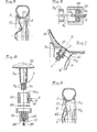
- FIG. 1 represents a wheel 1 of a motor vehicle equipped with a tubeless tire 2 or enveloping an inflatable air chamber provided with a valve 3, equipped with a cap 4.
- the wheel 1 comprises a pressure gauge 5 incorporated in the wheel coaxially therewith.
- the pressure gauge 5 is connected by a small pipe 6 to the valve 3.
- the pressure gauge and the pipe are integral with the wheel and rotate with it and the device is simple to build since it has no rotating joint between a fixed part and a rotating part.
- the arrangement of the pressure gauge in the center of the wheel, coaxial to it, allows to accommodate a pressure gauge with a large diameter, on the order of 50 to 60 mm in diameter, easy to read even from a distance and without unbalancing dynamically and statically wheel.
- the manometer 1 can be a manometer with a movable needle in front of a scale or a digital manometer indicating the digital measurement of the pressure.
- the aim of the present invention is to make it particularly practical to assess the state of the pressures effective exerted in the wheels of the vehicle (hereinafter referred to as actual pressures) and the pressures recommended by the automobile manufacturers (hereinafter referred to as theoretical pressures), varying according to the types of casings and according to their positions (mounting on the front or rear wheels).
- An immediate realization could consist in the adoption of a conventional display system, the real pressure being indicated by a needle rotated by the amplification system and moving in front of a fixed dial graduated for example in bars.
- the theoretical pressure would be displayed thanks to an index, fixed on the glass of the manometer, and capable of being moved in rotation according to a conventional assembly. The difference between the actual pressure and the theoretical pressure would thus be visualized by the difference existing between these two needles.
- a simple solution consists in printing these colored areas on the transparent disc closing the front face of the pressure gauge which will take the shape of a cylinder, with a height of at least 5 millimeters, this prominence giving the user a grip for allow rotation.
- the graduated dial it will be transferred to another set, presented to the user in the form of a key ring described below.
- FIG. 2 thus represents a front view of a mode of preferential realization of a manometer making it possible to immediately compare the value of the real pressure with the theoretical pressure.
- the front face of the manometer is a transparent disc 7 which is extended by a cylindrical rim 7a.
- This disc and the flange are pivotally mounted around the axis of the pressure gauge.
- the rim 7a makes it possible to grasp the disc in order to rotate it in order to adjust the angular position of the disc and of the colored sectors.
- the internal face of the disc carries, on its periphery, three juxtaposed colored sectors 8, 9 and 10. The colored sectors are located at the periphery of the disc so that the needle II can be seen through the central area of the disc transparent.
- the central sector 8 of orange color covers for example a range corresponding to 0.3 bar, normal range of use.
- Sector 9 located to the left of sector 8 indicates a pressure lower than the theoretical pressure. For example, it covers a range of 1 bar. It is colored red to indicate to the driver not to continue driving at this pressure and that the tire must be re-inflated.
- Sector 10 on the right indicates a pressure higher than the theoretical pressure. It covers, for example, a range of 0.6 bar, corresponding to the generally authorized and even recommended overpressures when the vehicle is overloaded and has to drive long at high speed, this situation being encountered on motorways.
- Sector 10 is for example colored green.
- the international road symbol STOP may be printed on the road zone and the motorway signs appear on the green sector.
- the pressure gauge will include a reading range, the amplitude of which will correspond to the pressure variation ranging from 1.2 bar to 3.1 bar.
- An examination of the catalogs of the envelope manufacturers shows that the minimum operating pressure, on all of the tires produced, is 1.5 bar. Therefore, the range from 0 to 1.5 bar will be of no interest to the user. However, the motorist must be given the opportunity to assess the pressure drop, with an amplitude allowing visualization of a pressure drop of 0.3 bar, corresponding to the orange range previously considered. Thus, the minimum pressure indicated by the device will be 1.2 bar.
- This pressure gauge will thus include a minimum stop at 1.2 bar and a maximum stop at 3.1 bar.
- the rim 7a is forced into the metal housing 20, the circular boss located at the end of the rim 7a being received in a groove formed in the metal housing 20.
- This simple method of fixing ensures rotation of the cylinder 7 relative to the housing 20, while ensuring the water and dust tightness between these two parts.
- the driver of the vehicle very quickly sees, without having to perform any maneuver, whether the needle 11 is located in the overpressure sector 10, in which case the pressure is correct or if, on the contrary, the needle 11 is located in sector 9, zone where it is necessary to envisage a re-pressure or even to the left of it, in which case it becomes imperative to immediately re-inflate the tire.
- Figure 3 is an axial section of the central part of a wheel according to the invention equipped with a pressure gauge 5.
- This figure shows the end 16 of a wheel spindle, the axis x xl and the web 17 of the wheel which is pierced with a central orifice 18.
- the pressure gauge 5 is housed in the orifice 18.
- FIG. 3 shows the cylindrical housing 20 of the pressure gauge which is fixed coaxially on the web 17.
- the housing 20 is in the form of two coaxial cylinders, nested one inside the other, the smaller of the two cylinders being fixed to the rear face and enveloping the end of the rocket 16. This hollow arrangement makes it possible to reduce the overshoot of the pressure gauge relative to the center of the wheel face.
- the pressure gauge shown comprises a metal spiral pressure tube 21 or Bourdon tube, connected to the valve 3 by a pipe 6 and housed between the two cylinders of the housing.
- the movements of the end of the pressure tube are transformed into a rotation movement around the axis by a movement transmission and amplification device 22 which rotates the axis 22a carrying the needle 11, which moves in front of a dial 13 without numerical indications.
- the end of this connection may end in a valve cap 25, which is screwed onto the brass end of the valve, by compressing a seal 26 between the end of the valve and a nozzle 6a to which the connecting pipe 6 will be fixed.
- This nozzle 6a will have a pusher 6b coming to open the valve valve 3c, thus putting the air chamber and the pressure gauge into communication.
- the connecting line 6 will travel inside the wheel disc 17, thus being sheltered from shocks and possible tears.
- an orifice in the rim web 17 will allow the pipe 6 to pass through it to be connected to the base of the valve 3, thus benefiting from the protection offered by the connection of the web 17 to the rim 27.
- FIG. 7 shows a part of a wheel rim 30 and a part of the wheel disc 31, in the center of which a pressure gauge, not shown, is fixed.
- the rim 30 receives a tubeless tire 32 or a tire with a chamber 33 fitted with a valve 3 of axis y yl, which passes through an orifice in the rim.
- the pipe 6 is housed at the rear of the web 31 to be protected from shocks and it passes through a bore 31a of the web which is located behind the valve 3.
- the valve 3 usually comprises a conical base 3a coated of rubber and a male threaded end 3b provided with a central rod 3c which makes it possible to open the valve flap.
- the pipe 6 is equipped at its end with a brass ring 34 having a conical internal bearing 34a, of the same conicity as the conical base 3a.
- the pipe 6 is connected perpendicular to the axis of the ring 34, halfway up the latter.
- the attachment further comprises a threaded cap 35 which screws onto the threaded end 3b of the valve.
- a seal 39 is placed between the ring 34 and the cap 35. The screwing of the cap 35 on the threaded end piece 3b crushes the seal 39 and it presses, sealingly, the conical bearing 34a against the conical base 3a of the valve.
- the cap 35 carries a pusher 36 which abuts against the rod 3c for opening the valve flap.
- the pusher 36 can be an integral part of the cap 35.
- the pusher 36 is operated by a rod 37 provided with an external button 38.
- a seal 40 seals between the rod 37 and the cap 35.
- the ring 34 is engaged on the conical base 3a of the valve.
- the cap 35 is then screwed onto the threaded end piece 3b of the valve and the valve is opened. Subsequently, when the tire has to be re-inflated, it suffices to unscrew the cap 35 to release the threaded end piece 3b, leaving the ring 34 around the valve.
- This solution makes it possible to place the pipe 6 behind the rim web and to house the end of the latter in the groove formed by the junction between the rim 30 and the web 31, which gives good protection against impacts and tears.
- Another variant consists in providing a threaded push button. no valves, screwed into the cap 35, and allowing this pusher to be adjustable relative to this cap 35. It then becomes possible, depending on the relative position of the end of the rod 3c relative to the threaded end 3b, to obtain the opening of the valve flap even if by construction the end of the rod 3c is very set back from the threaded end.
- the end of the pipe 6 preferably comprises a calibrated nozzle 41 of small diameter, which will not interfere with the transmission of the static pressure but which limits the oscillations of the pressure during the movements of the vehicle. If the pressure gauge or line 6 is destroyed, thanks to this calibrated nozzle, the tire deflates slowly, as if it were a puncture.
- a variant of the two preceding arrangements consists in fixing the pressure gauge 5 on a hub cap 42, the path of the connecting pipe 6 being carried out for half. between the hubcap of the hub 42 and the wheel disc 17, and for the other half of the route behind the wheel disc 17, by virtue of the veil bores 31b and 31c.
- connection of the end of the connecting pipe 6 to the valve 3 is always carried out according to the assembly described in FIGS. 7 and 8.
- This assembly involves the permanent attachment of the hub cap 42 to the wheel disc 17.
- the pressure gauge which has just been described does not include any graduated numerical scale in order to facilitate reading in all positions and to allow easy adaptation to all types of tires.
- This scale will have the shape of a circular abacus comprising, on each of its two faces, a movable scale corresponding one to the manometers of the front wheels, the other to the manometers of the rear wheels whose pressures are often distinct. Each of these faces will have a graduated peripheral scale going from 1, 2 to 3 bars, so that it will include all the usual pressures.
- Each face will also include a rotating mobile disc carrying colored sectors with the same angular opening as the colored sectors 8, 9 and 10.
- a rotating mobile disc carrying colored sectors with the same angular opening as the colored sectors 8, 9 and 10.
- Each face will also have a needle that can move in rotation around the axis, which the driver of the vehicle will place in the same relative position with respect to the colored sectors as that which he will observe on the pressure gauge and the driver will then read the numerical value of the pressure on the graduation which will be in front of the needle.
- the hot pressure after a high-speed journey can be increased by 0.2 to 0.3 bar as a result of the heating it then undergoes.
- the keychain can advantageously be provided with a thermometer which, applied against the tire tread, will indicate the temperature.
- a mobile temperature correction scale will then be provided on each reading scale, allowing the pressure read to be corrected to bring it back to the cold value, the user having displayed, thanks to the device, the temperature of the tire at the time of the previous one pressurizing.
- this pressure gauge key holder manipulated by the driver each time he uses the vehicle, will remind him of the presence of the pressure gauges on his wheels, prompting him to check the tire pressure more frequently.
Landscapes
- Engineering & Computer Science (AREA)
- Mechanical Engineering (AREA)
- Measuring Fluid Pressure (AREA)
- Pulleys (AREA)
Applications Claiming Priority (2)
| Application Number | Priority Date | Filing Date | Title |
|---|---|---|---|
| FR8115846A FR2511308A1 (fr) | 1981-08-14 | 1981-08-14 | Roue manometrique pour vehicule automobile |
| FR8115846 | 1981-08-14 |
Publications (3)
| Publication Number | Publication Date |
|---|---|
| EP0072768A2 true EP0072768A2 (de) | 1983-02-23 |
| EP0072768A3 EP0072768A3 (en) | 1983-03-16 |
| EP0072768B1 EP0072768B1 (de) | 1986-06-04 |
Family
ID=9261530
Family Applications (1)
| Application Number | Title | Priority Date | Filing Date |
|---|---|---|---|
| EP82430020A Expired EP0072768B1 (de) | 1981-08-14 | 1982-08-13 | Kraftfahrzeugrad mit Druckmesser |
Country Status (4)
| Country | Link |
|---|---|
| EP (1) | EP0072768B1 (de) |
| JP (1) | JPS5878804A (de) |
| DE (1) | DE3271553D1 (de) |
| FR (1) | FR2511308A1 (de) |
Cited By (7)
| Publication number | Priority date | Publication date | Assignee | Title |
|---|---|---|---|---|
| EP0417427A1 (de) * | 1989-09-09 | 1991-03-20 | WABCO Vermögensverwaltungs-GmbH | Einrichtung zur Überwachung des Druckes eines Fahrzeugreifens |
| FR2749224A1 (fr) * | 1996-06-03 | 1997-12-05 | Daniault Alain | Perfectionnements aux roues manometriques pour vehicules automobiles |
| WO1997046401A3 (fr) * | 1996-06-03 | 1998-04-02 | Alain Daniault | Perfectionnements aux roues manometriques |
| FR2770177A1 (fr) | 1997-10-27 | 1999-04-30 | Alain Daniault | Dispositif de controle de l'etat de gonflage d'un pneumatique par voyants |
| FR2771678A1 (fr) * | 1999-01-14 | 1999-06-04 | Alain Daniault | Dispositif de controle de gonflage de roues de vehicules |
| GB2359629A (en) * | 2000-02-25 | 2001-08-29 | Paul Kelly | Pressure gauge valve |
| WO2024018121A1 (fr) * | 2022-07-20 | 2024-01-25 | Patrick Herbault | Indicateur mécanique de pression de pneu avec alerte de sur-gonflage |
Families Citing this family (1)
| Publication number | Priority date | Publication date | Assignee | Title |
|---|---|---|---|---|
| JPH01109406U (de) * | 1988-01-20 | 1989-07-24 |
Family Cites Families (9)
| Publication number | Priority date | Publication date | Assignee | Title |
|---|---|---|---|---|
| GB291230A (en) * | 1927-05-27 | 1928-05-31 | Charles William Godson Little | Improvements in pressure indicating devices for use with pneumatic tyres |
| GB330898A (en) * | 1929-03-18 | 1930-06-18 | Arthur George Foulds | Improvements relating to deflation indicating means for motor vehicles and aircraft fitted with pneumatic tyres |
| FR790516A (fr) * | 1935-05-24 | 1935-11-22 | Indicateur de crevaison et de dégonflement des pneumatiques d'automobiles | |
| US2119287A (en) * | 1936-10-19 | 1938-05-31 | Pratt Robert James | Pneumatic tire gauge |
| US2575849A (en) * | 1945-03-21 | 1951-11-20 | Ray L Steven | Tire pressure indicator |
| GB636470A (en) * | 1946-12-04 | 1950-05-03 | Federico Carlos Kember | Fluid pressure indicating device |
| FR1030246A (fr) * | 1950-12-29 | 1953-06-10 | Appareil indiquant la pression contenue dans les pneumatiques à bord de tout véhicule | |
| US3260233A (en) * | 1963-12-05 | 1966-07-12 | Richard Jousma | Air pressure gauge for pneumatic tires |
| US3303696A (en) * | 1964-06-03 | 1967-02-14 | Carl R Capparclle | Tire pressure gauge |
-
1981
- 1981-08-14 FR FR8115846A patent/FR2511308A1/fr active Granted
-
1982
- 1982-08-13 DE DE8282430020T patent/DE3271553D1/de not_active Expired
- 1982-08-13 JP JP57140007A patent/JPS5878804A/ja active Pending
- 1982-08-13 EP EP82430020A patent/EP0072768B1/de not_active Expired
Cited By (8)
| Publication number | Priority date | Publication date | Assignee | Title |
|---|---|---|---|---|
| EP0417427A1 (de) * | 1989-09-09 | 1991-03-20 | WABCO Vermögensverwaltungs-GmbH | Einrichtung zur Überwachung des Druckes eines Fahrzeugreifens |
| FR2749224A1 (fr) * | 1996-06-03 | 1997-12-05 | Daniault Alain | Perfectionnements aux roues manometriques pour vehicules automobiles |
| WO1997046401A3 (fr) * | 1996-06-03 | 1998-04-02 | Alain Daniault | Perfectionnements aux roues manometriques |
| FR2770177A1 (fr) | 1997-10-27 | 1999-04-30 | Alain Daniault | Dispositif de controle de l'etat de gonflage d'un pneumatique par voyants |
| FR2771678A1 (fr) * | 1999-01-14 | 1999-06-04 | Alain Daniault | Dispositif de controle de gonflage de roues de vehicules |
| GB2359629A (en) * | 2000-02-25 | 2001-08-29 | Paul Kelly | Pressure gauge valve |
| WO2024018121A1 (fr) * | 2022-07-20 | 2024-01-25 | Patrick Herbault | Indicateur mécanique de pression de pneu avec alerte de sur-gonflage |
| FR3138067A1 (fr) * | 2022-07-20 | 2024-01-26 | Patrick Herbault | Indicateur mécanique de pression de pneu avec alerte de sur-gonflage |
Also Published As
| Publication number | Publication date |
|---|---|
| EP0072768B1 (de) | 1986-06-04 |
| DE3271553D1 (en) | 1986-07-10 |
| EP0072768A3 (en) | 1983-03-16 |
| FR2511308A1 (fr) | 1983-02-18 |
| JPS5878804A (ja) | 1983-05-12 |
| FR2511308B1 (de) | 1984-04-13 |
Similar Documents
| Publication | Publication Date | Title |
|---|---|---|
| EP3642057B1 (de) | System zur auswertung der verformung eines reifenmantels | |
| US4924697A (en) | Tire-mounted air pressure gauge assembly | |
| EP0072768B1 (de) | Kraftfahrzeugrad mit Druckmesser | |
| FR2497154A1 (fr) | Avertisseur de degonflement de pneu sans chambre pour automobiles | |
| EP0975477B1 (de) | Notlaufeinsatz mit generierung eines transversalen vibrationssignals und vorrichtung zur detektion des infunktiontretens eines notlaufeinsatzes innerhalb eines reifens | |
| CA2441811A1 (fr) | Systeme de regulation de la pression de gonflage d'un pneumatique | |
| EP0606511B1 (de) | Warnvorrichtung und -anlage für Reifenunterdruck und speziell dafür ausgebildetes Rad | |
| EP0041511B1 (de) | Vorrichtung mit fernanzeige zum vergleich eines kraftfahrzeugreifendruckes mit einem soll-wert | |
| WO2006061479A1 (fr) | Roue pour vehicule et systeme de contrôle de sa pression de gonflage | |
| EP0775601B1 (de) | Rad mit Sicherheitsstütze und eingebautem Druckmessfühler | |
| FR2944231A1 (fr) | Evaluation d'une deformation peripherique d'un pneumatique en cours d'utilisation | |
| EP2703798A1 (de) | Druckmessgerät | |
| EP3492288B1 (de) | Gerät zum testen eines kalibrierten gaslecks an einem reifenventil, verschlusskappe für ein solches gerät und entsprechendes verfahren zur kontrolle der leckerkennung | |
| EP3529088B1 (de) | Visueller indikator für reifenfüllsystem | |
| FR2897015A1 (fr) | Vehicule automobile a reparation automatique d'une crevaison et palier pour mettre en oeuvre cette fonction de facon optionnelle | |
| WO2019115494A1 (fr) | Ensemble monte pour vehicule avec un systeme de surveillance de caracteristique d'un bandage pneumatique ferme | |
| FR2771678A1 (fr) | Dispositif de controle de gonflage de roues de vehicules | |
| FR2572029A1 (fr) | Capteur de la pression de gonflage d'un pneumatique de vehicule | |
| FR3165419A1 (fr) | Procédé de lecture des informations contenues dans une puce RFID noyée dans un pneumatique de véhicule | |
| FR2922485A1 (fr) | Dispositif de prise de mesure pour roue equipee d'une chambre a air | |
| EP1232881B1 (de) | Regelsystem für den Druck in einer Kapazität, wie ein Fahrzeugrad | |
| FR2579323A1 (fr) | Dispositif magnetique de controle de la pression des pneumatiques | |
| WO1997046401A2 (fr) | Perfectionnements aux roues manometriques | |
| FR2762260A1 (fr) | Insert de securite generant un signal vibratoire transversal et dispositif de detection de la mise en appui d'un pneumatique sur un insert | |
| FR2749224A1 (fr) | Perfectionnements aux roues manometriques pour vehicules automobiles |
Legal Events
| Date | Code | Title | Description |
|---|---|---|---|
| PUAI | Public reference made under article 153(3) epc to a published international application that has entered the european phase |
Free format text: ORIGINAL CODE: 0009012 |
|
| PUAL | Search report despatched |
Free format text: ORIGINAL CODE: 0009013 |
|
| AK | Designated contracting states |
Designated state(s): BE CH DE FR GB IT LI |
|
| AK | Designated contracting states |
Designated state(s): BE CH DE FR GB IT LI |
|
| 17P | Request for examination filed |
Effective date: 19830207 |
|
| GRAA | (expected) grant |
Free format text: ORIGINAL CODE: 0009210 |
|
| AK | Designated contracting states |
Kind code of ref document: B1 Designated state(s): BE CH DE FR GB IT LI |
|
| REF | Corresponds to: |
Ref document number: 3271553 Country of ref document: DE Date of ref document: 19860710 |
|
| ITF | It: translation for a ep patent filed | ||
| PLBE | No opposition filed within time limit |
Free format text: ORIGINAL CODE: 0009261 |
|
| STAA | Information on the status of an ep patent application or granted ep patent |
Free format text: STATUS: NO OPPOSITION FILED WITHIN TIME LIMIT |
|
| 26N | No opposition filed | ||
| ITTA | It: last paid annual fee | ||
| PGFP | Annual fee paid to national office [announced via postgrant information from national office to epo] |
Ref country code: BE Payment date: 19970911 Year of fee payment: 16 |
|
| PG25 | Lapsed in a contracting state [announced via postgrant information from national office to epo] |
Ref country code: BE Free format text: LAPSE BECAUSE OF NON-PAYMENT OF DUE FEES Effective date: 19980831 |
|
| BERE | Be: lapsed |
Owner name: DANIAULT ALAIN Effective date: 19980831 |
|
| PGFP | Annual fee paid to national office [announced via postgrant information from national office to epo] |
Ref country code: DE Payment date: 20000811 Year of fee payment: 19 |
|
| PGFP | Annual fee paid to national office [announced via postgrant information from national office to epo] |
Ref country code: CH Payment date: 20000815 Year of fee payment: 19 |
|
| PGFP | Annual fee paid to national office [announced via postgrant information from national office to epo] |
Ref country code: FR Payment date: 20000831 Year of fee payment: 19 |
|
| PGFP | Annual fee paid to national office [announced via postgrant information from national office to epo] |
Ref country code: GB Payment date: 20010807 Year of fee payment: 20 |
|
| PG25 | Lapsed in a contracting state [announced via postgrant information from national office to epo] |
Ref country code: LI Free format text: LAPSE BECAUSE OF NON-PAYMENT OF DUE FEES Effective date: 20010831 Ref country code: CH Free format text: LAPSE BECAUSE OF NON-PAYMENT OF DUE FEES Effective date: 20010831 |
|
| REG | Reference to a national code |
Ref country code: GB Ref legal event code: IF02 |
|
| REG | Reference to a national code |
Ref country code: CH Ref legal event code: PL |
|
| PG25 | Lapsed in a contracting state [announced via postgrant information from national office to epo] |
Ref country code: FR Free format text: LAPSE BECAUSE OF NON-PAYMENT OF DUE FEES Effective date: 20020430 |
|
| PG25 | Lapsed in a contracting state [announced via postgrant information from national office to epo] |
Ref country code: DE Free format text: LAPSE BECAUSE OF NON-PAYMENT OF DUE FEES Effective date: 20020501 |
|
| REG | Reference to a national code |
Ref country code: FR Ref legal event code: ST |
|
| PG25 | Lapsed in a contracting state [announced via postgrant information from national office to epo] |
Ref country code: GB Free format text: LAPSE BECAUSE OF EXPIRATION OF PROTECTION Effective date: 20020812 |
|
| REG | Reference to a national code |
Ref country code: GB Ref legal event code: PE20 Effective date: 20020812 |