EP0072901A1 - Procédé et dispositif pour le chauffage uniforme de pièces allongées par induction - Google Patents
Procédé et dispositif pour le chauffage uniforme de pièces allongées par induction Download PDFInfo
- Publication number
- EP0072901A1 EP0072901A1 EP82105569A EP82105569A EP0072901A1 EP 0072901 A1 EP0072901 A1 EP 0072901A1 EP 82105569 A EP82105569 A EP 82105569A EP 82105569 A EP82105569 A EP 82105569A EP 0072901 A1 EP0072901 A1 EP 0072901A1
- Authority
- EP
- European Patent Office
- Prior art keywords
- inductor
- workpiece
- section
- thicker
- length
- Prior art date
- Legal status (The legal status is an assumption and is not a legal conclusion. Google has not performed a legal analysis and makes no representation as to the accuracy of the status listed.)
- Withdrawn
Links
- 238000010438 heat treatment Methods 0.000 title claims abstract description 40
- 238000000034 method Methods 0.000 title claims abstract description 38
- 230000008569 process Effects 0.000 title description 4
- 230000006698 induction Effects 0.000 title description 2
- 230000008878 coupling Effects 0.000 claims abstract description 17
- 238000010168 coupling process Methods 0.000 claims abstract description 17
- 238000005859 coupling reaction Methods 0.000 claims abstract description 17
- 230000001939 inductive effect Effects 0.000 claims abstract description 8
- 238000006073 displacement reaction Methods 0.000 claims description 17
- 238000005070 sampling Methods 0.000 claims 1
- 230000001960 triggered effect Effects 0.000 claims 1
- 230000032258 transport Effects 0.000 description 19
- 230000008719 thickening Effects 0.000 description 9
- 238000013461 design Methods 0.000 description 5
- 239000011248 coating agent Substances 0.000 description 3
- 238000000576 coating method Methods 0.000 description 3
- 239000006223 plastic coating Substances 0.000 description 3
- 239000007921 spray Substances 0.000 description 3
- XEEYBQQBJWHFJM-UHFFFAOYSA-N Iron Chemical compound [Fe] XEEYBQQBJWHFJM-UHFFFAOYSA-N 0.000 description 2
- 239000002826 coolant Substances 0.000 description 2
- 238000003780 insertion Methods 0.000 description 2
- 230000037431 insertion Effects 0.000 description 2
- 238000004519 manufacturing process Methods 0.000 description 2
- 239000000463 material Substances 0.000 description 2
- 239000003129 oil well Substances 0.000 description 2
- 239000003973 paint Substances 0.000 description 2
- 239000000523 sample Substances 0.000 description 2
- RYGMFSIKBFXOCR-UHFFFAOYSA-N Copper Chemical compound [Cu] RYGMFSIKBFXOCR-UHFFFAOYSA-N 0.000 description 1
- 240000004752 Laburnum anagyroides Species 0.000 description 1
- 241001024304 Mino Species 0.000 description 1
- 229910000831 Steel Inorganic materials 0.000 description 1
- 230000004913 activation Effects 0.000 description 1
- 230000006978 adaptation Effects 0.000 description 1
- 238000013459 approach Methods 0.000 description 1
- 239000011324 bead Substances 0.000 description 1
- 230000008901 benefit Effects 0.000 description 1
- 230000033228 biological regulation Effects 0.000 description 1
- 238000009500 colour coating Methods 0.000 description 1
- 229910052802 copper Inorganic materials 0.000 description 1
- 239000010949 copper Substances 0.000 description 1
- 230000000694 effects Effects 0.000 description 1
- 229910052742 iron Inorganic materials 0.000 description 1
- 238000003754 machining Methods 0.000 description 1
- 239000003208 petroleum Substances 0.000 description 1
- 238000012545 processing Methods 0.000 description 1
- 238000005086 pumping Methods 0.000 description 1
- 230000009467 reduction Effects 0.000 description 1
- 230000011664 signaling Effects 0.000 description 1
- 239000010959 steel Substances 0.000 description 1
- 238000012549 training Methods 0.000 description 1
Images


Classifications
-
- C—CHEMISTRY; METALLURGY
- C21—METALLURGY OF IRON
- C21D—MODIFYING THE PHYSICAL STRUCTURE OF FERROUS METALS; GENERAL DEVICES FOR HEAT TREATMENT OF FERROUS OR NON-FERROUS METALS OR ALLOYS; MAKING METAL MALLEABLE, e.g. BY DECARBURISATION OR TEMPERING
- C21D9/00—Heat treatment, e.g. annealing, hardening, quenching or tempering, adapted for particular articles; Furnaces therefor
- C21D9/0068—Heat treatment, e.g. annealing, hardening, quenching or tempering, adapted for particular articles; Furnaces therefor for particular articles not mentioned below
-
- C—CHEMISTRY; METALLURGY
- C21—METALLURGY OF IRON
- C21D—MODIFYING THE PHYSICAL STRUCTURE OF FERROUS METALS; GENERAL DEVICES FOR HEAT TREATMENT OF FERROUS OR NON-FERROUS METALS OR ALLOYS; MAKING METAL MALLEABLE, e.g. BY DECARBURISATION OR TEMPERING
- C21D1/00—General methods or devices for heat treatment, e.g. annealing, hardening, quenching or tempering
- C21D1/34—Methods of heating
- C21D1/42—Induction heating
-
- H—ELECTRICITY
- H05—ELECTRIC TECHNIQUES NOT OTHERWISE PROVIDED FOR
- H05B—ELECTRIC HEATING; ELECTRIC LIGHT SOURCES NOT OTHERWISE PROVIDED FOR; CIRCUIT ARRANGEMENTS FOR ELECTRIC LIGHT SOURCES, IN GENERAL
- H05B6/00—Heating by electric, magnetic or electromagnetic fields
- H05B6/02—Induction heating
- H05B6/10—Induction heating apparatus, other than furnaces, for specific applications
- H05B6/101—Induction heating apparatus, other than furnaces, for specific applications for local heating of metal pieces
- H05B6/103—Induction heating apparatus, other than furnaces, for specific applications for local heating of metal pieces multiple metal pieces successively being moved close to the inductor
- H05B6/104—Induction heating apparatus, other than furnaces, for specific applications for local heating of metal pieces multiple metal pieces successively being moved close to the inductor metal pieces being elongated like wires or bands
-
- Y—GENERAL TAGGING OF NEW TECHNOLOGICAL DEVELOPMENTS; GENERAL TAGGING OF CROSS-SECTIONAL TECHNOLOGIES SPANNING OVER SEVERAL SECTIONS OF THE IPC; TECHNICAL SUBJECTS COVERED BY FORMER USPC CROSS-REFERENCE ART COLLECTIONS [XRACs] AND DIGESTS
- Y02—TECHNOLOGIES OR APPLICATIONS FOR MITIGATION OR ADAPTATION AGAINST CLIMATE CHANGE
- Y02P—CLIMATE CHANGE MITIGATION TECHNOLOGIES IN THE PRODUCTION OR PROCESSING OF GOODS
- Y02P10/00—Technologies related to metal processing
- Y02P10/25—Process efficiency
Definitions
- the invention relates to a method for uniformly inductive heating of an elongated workpiece, in particular a pump rod and the like, which has a thinner length section, preferably extending over the main part of its length, with a substantially uniform cross section and at least one length section with a thicker cross section.
- the workpiece and a multi-wind inductor inductively coupled with it and enclosing the workpiece in the respective coupling area being moved relative to one another at a predetermined speed over a working path running in the longitudinal direction of the workpiece.
- the invention is directed to an expedient device for carrying out the method according to the invention.
- the invention is particularly suitable for heating pump rods, etc., in oil wells. Find use.
- the invention can also be used for the inductive heating of other elongate workpieces of various shapes and designs which have one or more cross-sectional thickenings along their length.
- Pump rods and the like are used in the petroleum industry as connecting rods between a pump located in the oil well and a lifting or pumping device arranged on the surface of the day.
- the pump rods have a relatively large length, which is generally on the order of 760 to 915 cm.
- the pump rod has a uniform cross-section over its main length region and has a cross-sectional thickening near its two ends. These cross-sectional thickenings serve to connect pump rods of the same type at the end.
- the common pump rods are of different designs, practically all pump rods have the above-mentioned basic features.
- the pump rods are heated to a predetermined temperature and then passed through an electrostatic spray chamber in which they are provided with a color coating or a coating made of a plastic-like material. Since the rods only need to be heated superficially during this operation, the heating is preferably carried out by induction. However, since the pump rods do not have a uniform, constant cross-section over their entire length, there is a need to compensate for the different heating temperatures that occur in the region of the rod ends at the thickenings present here in some way. An uneven heating of the pump rods over their entire length leads to the fact that the subsequently applied paint or plastic coating of uneven consistency, thickness and the like. is, in particular between the thinner main length area and the end-side rod thickening.
- the above object is achieved with the method according to the invention in that the relative speed between the workpiece and the inductor with magnetic coupling of the same with the thicker longitudinal section of the workpiece compared to the relative speed that exists with magnetic coupling of the inductor with the thinner longitudinal section of the workpiece, so far it is reduced that the thicker length section is heated to substantially the same temperature as the thinner length section of the workpiece with an increased effective heating time.
- the method can be carried out with particular advantage in such a way that during the inductive coupling of the inductor with a thicker length of the workpiece, the relative speed between the workpiece and the inductor is at least approximately eliminated for a predetermined time interval, so that the thicker length of the effect over a longer period of time of the inductor.
- the heating of the workpieces can advantageously be carried out in continuous continuous operation, and preferably in such a way that, during the heating of the larger and thinner length section, the workpiece is moved at a predetermined speed over the working distance to and through the inductor.
- the reduction in the relative speed between the workpiece and the inductor when the thicker longitudinal section of the workpiece is heated then expediently takes place in such a way that during the magnetic coupling of the inductor with the thicker longitudinal section, the inductor is moved in the same direction as the workpiece over the working distance.
- the workpiece can be heated uniformly while the workpiece is running at a constant and constant speed.
- the restoring movement of the inductor in the starting position can be carried out at a speed which deviates from the speed at which the inductor is moved in the same direction as the workpiece.
- the method according to the invention can be automated without special effort. It is recommended to use a touch device or the like. to use, which scans the thicker length of the workpiece before entering the inductor and which then triggers the tracking of the inductor after a predetermined time delay after the scanning.
- the method according to the invention is preferably carried out in such a way that the workpiece is moved over the working distance at a continuous speed.
- the inductor can also be operated with the same predetermined electrical power in its inductive coupling with the different length ranges of the workpiece in cross section.
- a device which is provided with an inductor device which has at least one multi-turn inductor coil through which the workpiece can be passed and with a current source assigned to the inductor device.
- a workpiece transport device that guides the workpieces through the inductor coil and transports them over the working distance, and also a displacement device or the like that moves the inductor device in the direction of the working distance.
- a probe device is provided which delivers a signal controlling the displacement device when a thicker workpiece section reaches a probe position in the vicinity of the input region of the inductor device.
- a time delay device is preferably provided, which the displacement device Signaling of the pushbutton device switches on with a time delay.
- the displacement device which expediently consists of a cylinder drive, is preferably designed so that it can be adjusted to different feed and return speeds of the inductor, the arrangement advantageously being such that it is possible to work with a slow and rapid return of the inductor.
- An arrangement is particularly advantageous in which at least one inductor is arranged on an inductor support designed in the manner of a carriage or carriage, which can be moved in the transport direction of the workpiece and in the opposite direction by means of the displacement device.
- a plurality of inductors can also be arranged in parallel with one another on the inductor carrier, so that several workpieces of the same type can be heated at the same time.
- Fig. 1 shows an elongated workpiece A, which is to be heated uniformly over its entire length.
- the workpiece A consists of a pump rod made of steel or another iron material, which has a central longitudinal section 10 which extends over its main length and, in contrast, thickened rod ends 12 and 14.
- the central lumen section 10 can have a circular, hexagonal cross section or another cross section. It has a uniform, constant cross-sectional size over its entire length.
- the thickened length regions 12 and 14 are essentially of the same design; they comprise a bead 16, a section 18 designed as a square key or provided with flats, and an end piece 20 designed as a sleeve or pin.
- FIG. 1 shows an elongated workpiece A, which is to be heated uniformly over its entire length.
- the workpiece A consists of a pump rod made of steel or another iron material, which has a central longitudinal section 10 which extends over its main length and, in contrast, thickened rod ends 12 and 14.
- these end pieces 20 each consist of a pin which in a last machining step has a thread is provided, so that the rod has a threaded pin at both ends, with which it can be screwed into the end threaded sleeve of another rod. It is therefore possible to connect several pump rods A by mechanical coupling at the end to form a pump rod of the desired length.
- the cross-sectional dimension of the central length section 10 of the pump rod is in the range between 12.5 mm and 28.5 mm, while the largest cross-sectional dimensions of the thickened length sections 12 and 14 are normally between 25.4 and 57.2 mm.
- the total length of the bar is approximately 760 to 915 cm, the length of the thickened sections 12 and 14 being relatively small and generally being only a few centimeters.
- different pump rods are also common. For example, some pump rods have a threaded pin at one end and an internally threaded threaded sleeve at their other end, so that similar rods can be connected at the end by screwing.
- the method according to the invention can also be used without problems in these and other designs of the rods.
- the device B shown for inductively heating the workpieces A has a multi-turn inductor 30 which consists of a cylindrical copper coil which has an essentially circular cross section.
- the individual turns of the coil, which are arranged at a lateral spacing from one another, are hollow, so that a continuous inner channel is formed, through which a coolant flows during operation.
- the coolant supply is in the vicinity of device B; it is of known training and therefore not shown in the drawing.
- the inductor 30 is arranged essentially coaxially to a linear working path W and has an input end 32 and an output end 34.
- the distance between the ends 32 and 34 of the inductor 30 is preferably approximately the same or slightly larger than the length of the individual thicker length sections 12 and 14.
- the coil is over electrical connecting lines 36 and 38 connected to a power source 40.
- the AC sources known in different versions, as are customary for the indicative heating of workpieces, can be used as the power source.
- the frequency and the power of the power source are of course adapted to the desired heating function.
- the connecting lines 36 and 38 are flexible so that they do not hinder the movement of the inductor 30 along the working distance W during the heating of the pump rod A at least over part of its length.
- the inductor 30 is expediently arranged in a housing 50 which is open at the end. It is mounted together with the housing on the top 52 of an inductor support 54, or the like in the manner of a carriage or carriage. is trained.
- the inductor support 54 is movably mounted on a frame or base frame 56.
- the frame or the underframe 56 is in turn on a base 58, e.g. the floor or the like attached.
- the inductor carrier 54 is arranged on the base frame 56 in such a way that the inductor 30 is in a coaxial position with respect to the working path W and is movable in the direction of the working path.
- the inductor carrier 54 is slidably guided on the base frame 56. It goes without saying that the inductor carrier 54 or the like also in bearings, sliding guides. could be guided on the base.
- a displacement device 70 is provided at the rear end of the inductor support for driving the inductor support 54.
- the displacement device consists of a pneumatic or hydraulic cylinder 72 which is connected to a fixed bracket 76 ododglo by means of a, for example, fork-shaped joint connection 74 arranged on the cylinder base.
- the piston rod end of the cylinder 72 is connected to the inductor carrier 54 by means of a joint connection 78.
- For optional pressurization of the at the pressure chambers of the cylinder 72 located on the sides of the piston are connected via pressure medium lines 80 and 82 to a pressure medium source (not shown), so that the piston rod 84 of the cylinder 72 connected to the inductor carrier 54 can optionally be extended or retracted.
- the arrangement is preferably such that the speed at which the pressure medium flows out of the respective cylinder space via the lines 80, 82 can be adjusted, so that the extension and retraction speed of the piston rod 84 can be controlled.
- a push button device 90 which has a limit switch, a proximity switch, a microswitch or the like. can have.
- the sensing device 90 is located approximately 61 cm from the inductor 30, although other arrangements of the sensing device could also be provided here.
- the feeler 90 scans the workpieces A moving over the working distance W to their thicker lengths 12, 14 and controls the displacement drive 70 of the inductor support 54.
- a time delay device 92 is preferably provided, which has the task of only moving the displacement drive 70 after a predetermined one , to turn on an adjustable period of time after activation of the push button device 90. During this switch-on delay, the scanned rod thickenings 12, 14 have the opportunity to move from the scanning position of the scanning device 90 into the inductor 30 and in magnetic coupling with it.
- the device shown finally has a support and transport device for transporting the workpieces A along the working path W.
- This device can also be of different designs.
- it consists of transport rollers 100 which are arranged in such a number and at such a roller spacing that they support the elongated workpieces A practically over their entire length.
- the transport rollers 100 have a roller drive (not shown), so that the workpieces A can be transported along the working path W by the rollers at a predetermined transport speed.
- the workpiece A is fed to the device B on the working path W at the predetermined transport speed in its longitudinal direction.
- the thickened length section 12 located at the front end of the workpiece approaches the feeler device 90, this is activated with the result that the displacement drive 70 is switched on after a predetermined time delay.
- the workpiece A continuously moves on the working path W into the inductor 30 and thus into the magnetic coupling with the inductor.
- the inductor is acted upon by the current source 40 with a predetermined current which is matched to the heating of the thinner and longer central section 10 of the workpiece A.
- the displacement becomes drive 72 switched on, so that the inductor carrier 54 is advanced with the inductor 30 in the transport direction of the workpiece A and at approximately the same speed as the workpiece A.
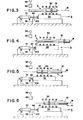
- the inductor carrier 54 moves from its normal or starting position 104 in the direction of arrow a, the piston rod 84 of the cylinder 72 being extended. This co-directional movement of the inductor carrier 54 together with the inductor 30 takes place over a predetermined period of time until the thicker length section 12 has been heated to the desired temperature within the predetermined upper and lower tolerance limits.
- the cylinder 72 is reversed in the direction of insertion, so that it retracts the inductor carrier 54 with the inductor 30 in the opposite direction b into the starting position 104 by inserting its piston rod 84.
- This situation is shown in Fig. 4.
- the workpiece A moves further along the working distance W with the predetermined continuous transport speed, so that the middle longer and thinner length section 10 now passes through the inductor 30 and is heated to the desired temperature.
- the zoB. is of the order of magnitude of approximately 760 cm, there is a sufficiently large period of time available for the return movement of the inductor carrier 54 into the starting position 104. It is advisable to move the inductor carrier 54 with the inductor 30 back to the starting position 104 at a relatively low speed, so that the longitudinal section 10 of the workpiece A is heated uniformly.
- FIG. 5 shows the thickened length section 14 lying at the rear end of the workpiece A after it has activated the touch device 90 during the passage and then has run into the inductor 30.
- This process is the same as previously described in connection with the front thicker length region 12.
- the drive cylinder 72 is switched on again so that it moves the inductor carrier 54 with the inductor 30 again in the same direction from the starting position 104 to the transport direction of the workpiece A. This process is indicated in Fig. 1 by arrow a.
- the drive cylinder 72 is reversed again in the direction of insertion, so as the inductor support 54 with the inductor 30 to the starting position 104 KirUckêt o Since in this Return movement of the inductor 30 has no heating function, as soon as the rear thicker length section 14 has left the inductor, the inductor carrier 54 is expediently moved back here at a higher return speed, that is to say in overdrive, so that the device is immediately ready for operation again. In this way it is possible to heat up successive workpieces A in the manner described.
- the heated workpiece A passes behind the device B through a coating device C, in which it is provided with the paint or plastic coating.
- This device C generally consists of an electrostatic spray chamber which is arranged at a short distance behind the heating device B.
- a spray chamber instead of a spray chamber, other devices can also be used for the workpiece coating.
- the device according to the invention and the method according to the invention can also be used for other purposes and in connection with other devices.
- the heating temperature is above 205 ° C.
- the long workpieces A can be heated within the permissible temperature tolerances of * 14 ° C.
- FIG. 7 shows a further exemplary embodiment of a device according to the invention in a top view, matching parts being provided with the same reference symbols but with an index '.
- two multi-winded In are on a common inductor support 54 ' ductors 30 'arranged in parallel to each other. Accordingly, two parallel working sections W 'leading through the inductors 30' are provided here.
- the two inductors 30 ' are each supplied by their own current source 40'. Instead of this, the inductor coils could also be acted upon by a single current source if the electrical connection was made accordingly.
- the device has two workpiece carrying and transport devices 110 and 112, each of which is aligned in the axial direction with the associated inductor 30 ′.
- two sensing devices 90 ' are arranged in the vicinity of the two inductors 30', which sense the thickened bars when the workpieces feed in over the two working sections W.
- the displacement device 70 'consisting of the cylinder drive or another drive displaces the common inductor carrier 54' in the forward direction, i.e. in the same direction as the transport direction of the workpieces and in the return direction to the starting position, as is the case in connection with the exemplary embodiment according to FIGS 6 has been explained. With the device according to FIG. 7, it is thus possible to heat up two pump rods or other workpieces simultaneously in the described procedure.
- a movable stop 114 or the like in the immediate vicinity of the two sensing devices 90'. provided, which extends across the two working sections W '. If both incoming workpieces are at the stop 114, this is raised or removed in some other way from the transport path of the workpieces, so that the workpieces now run into the two inductors 30 'and pass through them in the manner described.
- the stop 114 is expediently actuated automatically.
- FIG. 8 shows a further embodiment of a device according to the invention.
- Matching Parts of the device bear the same reference numbers, but with a double index line.
- two inductors 30 "arranged parallel to one another are each arranged on their own inductor carrier 54".
- Each inductor carrier 54 has its own displacement device 70" and its own (not shown) sensing device in the vicinity of the input end of the inductor 30 "in question.
- the workpieces are supplied via the two workpiece carrying and transporting devices 120 and 122 on the two parallel ones Working distances W ". With this device, the workpieces A can be heated independently of one another on the two working sections W "in the manner described. It is therefore not necessary here to feed the two workpieces to their inductors at the same time.
Landscapes
- Chemical & Material Sciences (AREA)
- Engineering & Computer Science (AREA)
- Physics & Mathematics (AREA)
- Thermal Sciences (AREA)
- Crystallography & Structural Chemistry (AREA)
- Mechanical Engineering (AREA)
- Materials Engineering (AREA)
- Metallurgy (AREA)
- Organic Chemistry (AREA)
- Power Engineering (AREA)
- Electromagnetism (AREA)
- General Induction Heating (AREA)
Applications Claiming Priority (2)
| Application Number | Priority Date | Filing Date | Title |
|---|---|---|---|
| US06/294,932 US4418259A (en) | 1981-08-21 | 1981-08-21 | Method and apparatus of uniform induction heating of an elongated workpiece |
| US294932 | 1981-08-21 |
Publications (1)
| Publication Number | Publication Date |
|---|---|
| EP0072901A1 true EP0072901A1 (fr) | 1983-03-02 |
Family
ID=23135538
Family Applications (1)
| Application Number | Title | Priority Date | Filing Date |
|---|---|---|---|
| EP82105569A Withdrawn EP0072901A1 (fr) | 1981-08-21 | 1982-06-24 | Procédé et dispositif pour le chauffage uniforme de pièces allongées par induction |
Country Status (3)
| Country | Link |
|---|---|
| US (1) | US4418259A (fr) |
| EP (1) | EP0072901A1 (fr) |
| CA (1) | CA1180769A (fr) |
Cited By (4)
| Publication number | Priority date | Publication date | Assignee | Title |
|---|---|---|---|---|
| EP0106421A1 (fr) * | 1982-09-09 | 1984-04-25 | Park-Ohio Industries, Inc. | Procédé et dispositif pour le chauffage uniforme d'une pièce allongée par induction |
| EP0439678A3 (en) * | 1990-01-30 | 1992-12-23 | Aeg-Elotherm Gmbh | Inductor |
| EP0597240B1 (fr) * | 1992-10-28 | 1997-01-02 | Daimler-Benz Aerospace Aktiengesellschaft | Dispositif et procédé d'injection |
| EP1721994A1 (fr) * | 2005-05-11 | 2006-11-15 | HWG Inductoheat GmbH | Installation de chauffage par induction pour le chauffage de plusieurs pièces de façon simultanée |
Families Citing this family (10)
| Publication number | Priority date | Publication date | Assignee | Title |
|---|---|---|---|---|
| US4482793A (en) * | 1982-03-15 | 1984-11-13 | Park-Ohio Industries, Inc. | Apparatus for simultaneously heating a plurality of elongated workpieces |
| US7582851B2 (en) * | 2005-06-01 | 2009-09-01 | Inductotherm Corp. | Gradient induction heating of a workpiece |
| DE102006048580C5 (de) * | 2006-10-13 | 2015-02-19 | Fraunhofer-Gesellschaft zur Förderung der angewandten Forschung e.V. | Verfahren und Vorrichtung zum rissfreien Schweißen, Reparaturschweißen oder Auftragsschweißen heißrissanfälliger Werkstoffe |
| US9131536B2 (en) | 2011-02-14 | 2015-09-08 | Bernard Fryshman | Induction cooking apparatus and method of use |
| US9888530B2 (en) | 2011-02-14 | 2018-02-06 | Bernard Fryshman | Induction cooking apparatus and induction cookware |
| US20170019957A1 (en) * | 2015-07-17 | 2017-01-19 | Bernard Fryshman | Induction cooking and heating systems |
| US10105069B2 (en) | 2016-04-20 | 2018-10-23 | Bernard Fryshman | Induction heating applications |
| US10328249B2 (en) | 2017-05-02 | 2019-06-25 | Bernard Fryshman | Applications using induction |
| US11524320B2 (en) * | 2019-07-11 | 2022-12-13 | Baranko Environmental LLC | Sucker rod cleaning using inductive heating |
| US12383939B2 (en) | 2023-02-21 | 2025-08-12 | Baranko Environmental LLC | Oilfield tubing cleaning |
Citations (8)
| Publication number | Priority date | Publication date | Assignee | Title |
|---|---|---|---|---|
| FR815003A (fr) * | 1936-12-10 | 1937-07-05 | Perfectionnements au traitement thermique de pièces | |
| US2490104A (en) * | 1945-04-12 | 1949-12-06 | Ohio Crankshaft Co | Apparatus for equalized induction heating of workpieces |
| FR1557249A (fr) * | 1967-03-01 | 1969-02-14 | ||
| DE1508430A1 (de) * | 1965-06-22 | 1969-10-23 | Ohio Crankshaft Company | Geraet zur Oberflaechenhaertung von laenglichen Stahlwerkstuecken |
| DE1533955A1 (de) * | 1967-04-29 | 1970-02-05 | Aeg Elotherm Gmbh | Verfahren und Vorrichtung zum induktiven Waermebehandeln von Werkstuecken aus Stahl |
| US3743808A (en) * | 1972-03-27 | 1973-07-03 | Growth International Inc | Method of controlling the induction heating of an elongated workpiece |
| FR2360674A1 (fr) * | 1976-08-03 | 1978-03-03 | Nippon Kokan Kk | Procede et appareil pour le traitement thermique par induction de pieces metalliques |
| DE2801661A1 (de) * | 1978-01-16 | 1979-08-02 | Aeg Elotherm Gmbh | Einrichtung zur induktionserwaermung eines langgestreckten werkstuecks |
Family Cites Families (13)
| Publication number | Priority date | Publication date | Assignee | Title |
|---|---|---|---|---|
| US1690612A (en) * | 1925-11-25 | 1928-11-06 | Columbus Sucker Rod Company | Method of making sucker rods |
| US1764068A (en) * | 1927-01-08 | 1930-06-17 | Emsco Derrick & Equip Co | Steel sucker rod and the like and its production |
| US2281850A (en) * | 1939-02-14 | 1942-05-05 | Bethlehem Steel Corp | Sucker rod steel |
| US2811623A (en) * | 1956-03-29 | 1957-10-29 | Loftus Engineering Corp | Method of heating metal billets by low frequency electrical power |
| US3057985A (en) * | 1959-01-20 | 1962-10-09 | Paul P Biringer | Method and system for dual frequency heating having a single frequency power source |
| US3604882A (en) * | 1970-07-24 | 1971-09-14 | Park Ohio Industries Inc | Power control device for an inductor |
| US3610861A (en) * | 1970-11-19 | 1971-10-05 | Ajax Magnethermic Corp | Induction heating of elongated bars |
| US3784780A (en) * | 1973-01-08 | 1974-01-08 | Park Ohio Industries Inc | Apparatus and method of inductively heating spaced surfaces on an elongated workpiece |
| US4117293A (en) * | 1974-11-14 | 1978-09-26 | Bbc Brown, Boveri & Company Limited | Method for conveying a row of forging ingots through an inductive heating apparatus |
| JPS5316939A (en) * | 1976-07-30 | 1978-02-16 | Nippon Steel Corp | Inducton heating method |
| US4075450A (en) * | 1976-02-23 | 1978-02-21 | American Induction Heating Corporation | Induction heater for forging bar stock |
| US4093839A (en) * | 1976-04-02 | 1978-06-06 | Ajax Magnethermic Corporation | Apparatus and method for inductively heating metallic tubing having an upset portion |
| US4289944A (en) * | 1977-12-19 | 1981-09-15 | Reese Thurston F | Apparatus for reheating, storing and conveying cast bars |
-
1981
- 1981-08-21 US US06/294,932 patent/US4418259A/en not_active Expired - Fee Related
-
1982
- 1982-03-04 CA CA000397612A patent/CA1180769A/fr not_active Expired
- 1982-06-24 EP EP82105569A patent/EP0072901A1/fr not_active Withdrawn
Patent Citations (8)
| Publication number | Priority date | Publication date | Assignee | Title |
|---|---|---|---|---|
| FR815003A (fr) * | 1936-12-10 | 1937-07-05 | Perfectionnements au traitement thermique de pièces | |
| US2490104A (en) * | 1945-04-12 | 1949-12-06 | Ohio Crankshaft Co | Apparatus for equalized induction heating of workpieces |
| DE1508430A1 (de) * | 1965-06-22 | 1969-10-23 | Ohio Crankshaft Company | Geraet zur Oberflaechenhaertung von laenglichen Stahlwerkstuecken |
| FR1557249A (fr) * | 1967-03-01 | 1969-02-14 | ||
| DE1533955A1 (de) * | 1967-04-29 | 1970-02-05 | Aeg Elotherm Gmbh | Verfahren und Vorrichtung zum induktiven Waermebehandeln von Werkstuecken aus Stahl |
| US3743808A (en) * | 1972-03-27 | 1973-07-03 | Growth International Inc | Method of controlling the induction heating of an elongated workpiece |
| FR2360674A1 (fr) * | 1976-08-03 | 1978-03-03 | Nippon Kokan Kk | Procede et appareil pour le traitement thermique par induction de pieces metalliques |
| DE2801661A1 (de) * | 1978-01-16 | 1979-08-02 | Aeg Elotherm Gmbh | Einrichtung zur induktionserwaermung eines langgestreckten werkstuecks |
Cited By (4)
| Publication number | Priority date | Publication date | Assignee | Title |
|---|---|---|---|---|
| EP0106421A1 (fr) * | 1982-09-09 | 1984-04-25 | Park-Ohio Industries, Inc. | Procédé et dispositif pour le chauffage uniforme d'une pièce allongée par induction |
| EP0439678A3 (en) * | 1990-01-30 | 1992-12-23 | Aeg-Elotherm Gmbh | Inductor |
| EP0597240B1 (fr) * | 1992-10-28 | 1997-01-02 | Daimler-Benz Aerospace Aktiengesellschaft | Dispositif et procédé d'injection |
| EP1721994A1 (fr) * | 2005-05-11 | 2006-11-15 | HWG Inductoheat GmbH | Installation de chauffage par induction pour le chauffage de plusieurs pièces de façon simultanée |
Also Published As
| Publication number | Publication date |
|---|---|
| US4418259A (en) | 1983-11-29 |
| CA1180769A (fr) | 1985-01-08 |
Similar Documents
| Publication | Publication Date | Title |
|---|---|---|
| EP0070409B1 (fr) | Procédé et dispositif pour la trempe par induction de pièces élongées à paroi mince | |
| EP0384964B1 (fr) | Procédé et dispositif pour le durcissement par induction des surfaces ondulées d'une pièce | |
| DE2734986C2 (de) | Verfahren und Vorrichtung zum Induktionserhitzen eines langgestreckten metallischen Werkstückes | |
| EP0470536B1 (fr) | Outil de mesure de honage | |
| DE2161502A1 (de) | Vorrichtung zur Zuführung von Schweißdrähten | |
| DE3201352A1 (de) | Verfahren und vorrichtung zum induktiven erhitzen von langgestreckten metallischen werkstuecken mit verschieden dicken laengsabschnitten | |
| EP0613823A1 (fr) | Dispositif pour l'introduction simultanée d'un objet et d'un encart dans un récipient sous forme de boîte | |
| DE2320545C3 (de) | Vorrichtung zur Stauchumformung langgestreckter metallischer Werkstücke | |
| DD149568A5 (de) | Verfahren zur volumetrischen aufteilung von zu foerderndem stabfoermigem material | |
| DE1533955B2 (de) | Verfahren und vorrichtung zur induktiven waermebehandlung von werkstuecken aus stahl | |
| EP0878555B1 (fr) | Dispositif pour guider des pièces | |
| DE2531300A1 (de) | Anlage zur warmbehandlung oder -umformung von werkstuecken | |
| DE2157060A1 (de) | Verfahren und Einrichtung zum induktiven Erwärmen von Ventilsitzen u. dgl | |
| DE835032C (de) | Verfahren und Vorrichtung zum elektro-induktiven Erhitzen von langgestreckten Werkstuecken | |
| DE1508430A1 (de) | Geraet zur Oberflaechenhaertung von laenglichen Stahlwerkstuecken | |
| DE1583334B1 (de) | Verfahren und Vorrichtung zum induktiven Oberflaechenhaerten von Flanschwellen nach dem Gesamtflaechenumlaufverfahren | |
| DE3623119C1 (en) | Process for the inductive hardening of cylindrical bearing points with transition radii relieved with respect to the adjoining shaft parts and apparatus for carrying out the process | |
| DE7143333U (de) | Induktionsbeheizungseinrichtung insbesondere zum induktiven erwaermen der konischen ventilsitzflaechen eines motors | |
| EP0549821A1 (fr) | Procédé pour opérer le pierrage de forages et tête de pierrage pour la mise en oeuvre du procédé | |
| DE4002581C2 (fr) | ||
| DE1577064C3 (de) | Vorrichtung zum Bewegen der Stauchstahle an einer elektrischen Abbrenn-Schweißmaschine zum Verschweißen von C-förmigen Kettengliedern | |
| DE1583334C (de) | Verfahren und Vorrichtung zum induk tiven Oberflächenhärten von Flanschwellen nach dem Gesamtflachenumlaufverfahren | |
| DE10219264B4 (de) | Vorrichtung zum Einziehen einer Materialbahn | |
| DE877770C (de) | Vorrichtung zum fortschreitenden Erhitzen, insbesondere zum fortschreitenden Haerten, von metallischen Werkstuecken | |
| DE970634C (de) | Vorrichtung zum induktiven Erhitzen |
Legal Events
| Date | Code | Title | Description |
|---|---|---|---|
| PUAI | Public reference made under article 153(3) epc to a published international application that has entered the european phase |
Free format text: ORIGINAL CODE: 0009012 |
|
| 17P | Request for examination filed |
Effective date: 19820624 |
|
| AK | Designated contracting states |
Designated state(s): AT BE CH DE FR GB IT LI LU NL SE |
|
| STAA | Information on the status of an ep patent application or granted ep patent |
Free format text: STATUS: THE APPLICATION HAS BEEN WITHDRAWN |
|
| 18W | Application withdrawn |
Withdrawal date: 19851220 |
|
| RIN1 | Information on inventor provided before grant (corrected) |
Inventor name: LEWIS, JOHN CHARLES |