EP0073098A1 - Elektrischer Verbinder für Flachkabel - Google Patents
Elektrischer Verbinder für Flachkabel Download PDFInfo
- Publication number
- EP0073098A1 EP0073098A1 EP82303820A EP82303820A EP0073098A1 EP 0073098 A1 EP0073098 A1 EP 0073098A1 EP 82303820 A EP82303820 A EP 82303820A EP 82303820 A EP82303820 A EP 82303820A EP 0073098 A1 EP0073098 A1 EP 0073098A1
- Authority
- EP
- European Patent Office
- Prior art keywords
- cable
- bar
- latch bar
- adjacent
- catch
- Prior art date
- Legal status (The legal status is an assumption and is not a legal conclusion. Google has not performed a legal analysis and makes no representation as to the accuracy of the status listed.)
- Granted
Links
- 239000004020 conductor Substances 0.000 claims description 14
- 238000009413 insulation Methods 0.000 claims description 3
- 230000000149 penetrating effect Effects 0.000 claims description 2
- 238000006073 displacement reaction Methods 0.000 description 2
- 238000003780 insertion Methods 0.000 description 2
- 230000037431 insertion Effects 0.000 description 2
- 238000005728 strengthening Methods 0.000 description 2
- 230000006978 adaptation Effects 0.000 description 1
- 230000000881 depressing effect Effects 0.000 description 1
- 230000000694 effects Effects 0.000 description 1
- 230000014759 maintenance of location Effects 0.000 description 1
- 238000004519 manufacturing process Methods 0.000 description 1
- 238000007567 mass-production technique Methods 0.000 description 1
- 239000000463 material Substances 0.000 description 1
- 238000000465 moulding Methods 0.000 description 1
- 229920003023 plastic Polymers 0.000 description 1
- 239000004033 plastic Substances 0.000 description 1
Images
Classifications
-
- H—ELECTRICITY
- H01—ELECTRIC ELEMENTS
- H01R—ELECTRICALLY-CONDUCTIVE CONNECTIONS; STRUCTURAL ASSOCIATIONS OF A PLURALITY OF MUTUALLY-INSULATED ELECTRICAL CONNECTING ELEMENTS; COUPLING DEVICES; CURRENT COLLECTORS
- H01R12/00—Structural associations of a plurality of mutually-insulated electrical connecting elements, specially adapted for printed circuits, e.g. printed circuit boards [PCB], flat or ribbon cables, or like generally planar structures, e.g. terminal strips, terminal blocks; Coupling devices specially adapted for printed circuits, flat or ribbon cables, or like generally planar structures; Terminals specially adapted for contact with, or insertion into, printed circuits, flat or ribbon cables, or like generally planar structures
- H01R12/50—Fixed connections
- H01R12/59—Fixed connections for flexible printed circuits, flat or ribbon cables or like structures
- H01R12/65—Fixed connections for flexible printed circuits, flat or ribbon cables or like structures characterised by the terminal
- H01R12/67—Fixed connections for flexible printed circuits, flat or ribbon cables or like structures characterised by the terminal insulation penetrating terminals
- H01R12/675—Fixed connections for flexible printed circuits, flat or ribbon cables or like structures characterised by the terminal insulation penetrating terminals with contacts having at least a slotted plate for penetration of cable insulation, e.g. insulation displacement contacts for round conductor flat cables
-
- H—ELECTRICITY
- H01—ELECTRIC ELEMENTS
- H01R—ELECTRICALLY-CONDUCTIVE CONNECTIONS; STRUCTURAL ASSOCIATIONS OF A PLURALITY OF MUTUALLY-INSULATED ELECTRICAL CONNECTING ELEMENTS; COUPLING DEVICES; CURRENT COLLECTORS
- H01R12/00—Structural associations of a plurality of mutually-insulated electrical connecting elements, specially adapted for printed circuits, e.g. printed circuit boards [PCB], flat or ribbon cables, or like generally planar structures, e.g. terminal strips, terminal blocks; Coupling devices specially adapted for printed circuits, flat or ribbon cables, or like generally planar structures; Terminals specially adapted for contact with, or insertion into, printed circuits, flat or ribbon cables, or like generally planar structures
- H01R12/50—Fixed connections
- H01R12/59—Fixed connections for flexible printed circuits, flat or ribbon cables or like structures
- H01R12/62—Fixed connections for flexible printed circuits, flat or ribbon cables or like structures connecting to rigid printed circuits or like structures
-
- H—ELECTRICITY
- H01—ELECTRIC ELEMENTS
- H01R—ELECTRICALLY-CONDUCTIVE CONNECTIONS; STRUCTURAL ASSOCIATIONS OF A PLURALITY OF MUTUALLY-INSULATED ELECTRICAL CONNECTING ELEMENTS; COUPLING DEVICES; CURRENT COLLECTORS
- H01R13/00—Details of coupling devices of the kinds covered by groups H01R12/70 or H01R24/00 - H01R33/00
- H01R13/46—Bases; Cases
- H01R13/502—Bases; Cases composed of different pieces
- H01R13/506—Bases; Cases composed of different pieces assembled by snap action of the parts
-
- H—ELECTRICITY
- H01—ELECTRIC ELEMENTS
- H01R—ELECTRICALLY-CONDUCTIVE CONNECTIONS; STRUCTURAL ASSOCIATIONS OF A PLURALITY OF MUTUALLY-INSULATED ELECTRICAL CONNECTING ELEMENTS; COUPLING DEVICES; CURRENT COLLECTORS
- H01R4/00—Electrically-conductive connections between two or more conductive members in direct contact, i.e. touching one another; Means for effecting or maintaining such contact; Electrically-conductive connections having two or more spaced connecting locations for conductors and using contact members penetrating insulation
- H01R4/24—Connections using contact members penetrating or cutting insulation or cable strands
- H01R4/2416—Connections using contact members penetrating or cutting insulation or cable strands the contact members having insulation-cutting edges, e.g. of tuning fork type
- H01R4/242—Connections using contact members penetrating or cutting insulation or cable strands the contact members having insulation-cutting edges, e.g. of tuning fork type the contact members being plates having a single slot
Definitions
- the invention relates to electrical connector housings and, in particular, to an electrical connector housing for flat cable.
- U.S. Patent Specification 4,062,616 discloses a prior electrical connector housing for terminating flat cable comprising a base member and a cable locating member pivotally connected together at adjacent ends , a row of electrical terminals being mounted on the base member and having insulation penetrating conductor engaging portions projecting towards the cable location member so that, with the connector in an open condition in which the cable locating member is remote from the base member, flat cable can be located by the cable locating member and subsequent pivotal movement of the cable locating member towards the base member to place the connector in a closed condition will drive the conductor engaging portions into the cable to establish electrical connections with respective conductors of the cable.
- the connector referred to above is characterized in that the conductor engaging portions are located adjacent the pivotal connection so that a mechanical advantage is obtained when applying a closing force to the housing at locations spaced from the pivotal connection.
- the cable locating member comprises a cable receiving pocket extending from the pivotal connection to a cable-receiving mouth at an end remote from the pivotal connection, the cable receiving pocket being intersected by slots aligned to receive and guide the conductor-engaging portions on closing the housing.
- the pocket-form ensures ease of insertion and accuracy of location of the flat cable throughout the termination.
- housings of the insertion can be made from very few components, each of which can be produced by mass production techniques and readily assembled at low cost.
- the housings can be of very small size and ease of cable manipulation and termination facilitates their use on printed circuit boards.
- the base member and the cable locating member are provided with interengageable latching means comprising a latch bar and a release bar extending spaced apart in side-by-side relation and supported for deflection adjacent a free end of one member and interconnected by a plurality of transverse struts defining an eye, and catch means on the other member, receivable in the eye in latching engagement with the latch bar in the closed condition, movement of the release bar in the direction of the latch bar deflecting the release bar thereby to disengage the latch from the release bar.
- interengageable latching means comprising a latch bar and a release bar extending spaced apart in side-by-side relation and supported for deflection adjacent a free end of one member and interconnected by a plurality of transverse struts defining an eye, and catch means on the other member, receivable in the eye in latching engagement with the latch bar in the closed condition, movement of the release bar in the direction of the latch bar deflecting the release bar thereby to disengage the latch from the release
- Movement of the release bar in other directions will not disengage the latch from the release bar, avoiding inadvertent unlatching, but movement of the release bar in the correct direction will readily release the latch.
- the latch and release bars may be formed at the free end and extend in the same place as the one member.
- a very compact latching mechanism may be obtained.
- the housing may be mounted with the latching mechanism protruding beyond an edge of a printed circuit board so that no board space is obstructed by the latching mechanism.
- the latch bar is spaced from the one member by an elongate slot extending for a majority of the length of the latch bar.
- the provision of the slot enables the latch bar to be formed conveniently during moulding the one member.
- the latch bar and release bar are resiliently flexible and the latch bar is joined at respective opposite ends of the slot to the one member by relatively rigid webs, deflection of the release bar towards the one member flexing the latch bar to disengage the catch member from the latch bar.
- the provision of the rigid webs prevents inadvertent pressure on the bar in directions other than a release direction from breaking the latch bar away from the member.
- the struts define with the latch bar and the release bar a series of eyes and the latch bar has catch portions adjacent respective eyes, the catch portions adjacent lateral ends of the bar being located rearwardly, in the direction of deflection, of catch portions adjacent central portions of the bar.
- depression of the release bar in the release direction causes bowing of the latch bar into the slot which bowing is accommodated by the rearward staggering of the catch portions.
- the central portion of the latch bar is deflected more than lateral portions, secure latching and ready release are assured.
- an electrical connector housing comprising first and second members movable between mutally adjacent and remote positions corresponding to closed and open conditions of the housing respectively, latching means comprising a latch bar and a release bar supported for deflection adjacent an end of one member and extending spaced apart in side-by-side relation interconnected by a plurality of transverse struts to define an eye, and a catch on the other member receivable in the eye in latching engagement with the latch bar in the closed condition, movement of the release bar towards the latch bar deflecting the latch bar, thereby to disengage the catch from the release bar.
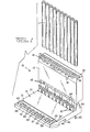
- electrical connector 10 for terminating ribbon cable 11 comprises a cable holder 12 and a base member 13 each molded in one piece from suitable plastics material and pivotally connected together along a rear end.
- the cable holder 12 is formed with a blind-ended pocket 14 having a cable receiving mouth at a front end and intersected by a series of guide slots 15 adjacent the blind end.
- a row of hooks 16 extend along the rear end.
- a row of apertured lugs 17 depend from a central part of the front edge of the holder and carry at free ends respective catches 18.
- An apertured guiding lug 19 depends from the front edge of the holder adjacent respective opposite ends of the row of lugs 17.
- the base 13 comprises a central platform 21 rearwardly of which are formed sockets 22 receiving terminals 23 arranged in a row and having bifurcated conductor engaging portions 24 at upper ends and legs 25 at lower ends for receipt in apertures in a printed circuit board 26.
- the terminals may each be formed with dimples, shoulders or other conventional adaptations to facilitate retention in the sockets 22 as an interference fit.
- the legs After receipt of the contacts in the sockets, the legs may be deformed to the desired configuration using the lips of the sockets as a former.
- a hinge pin 28 extends along the rear end supported at intervals along its length by flanges 30 and in pivotal engagement with the hooks 16.
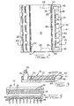
- a slot 31 extends downwardly into the platform adjacent the front end for substantially the entire depth of the platform so that only a thin web 32 remains at the slot base, the web being perforated at intervals by apertures 33.
- the slot defines a resiliently flexible latch bar 35 extending along the front end and integrally joined at respective opposite ends by webs 34 to the platform 21.
- the latch bar 35 is connected at intervals by transverse bridges or struts 4 0 to a resiliently flexible release bar 41 extending in parallel relation with the latch bar 35.
- the struts 40 stiffen the latch and release bars and define between them, eyes 42 and 43 aligned with the respective lugs 17 and 19 depending from the holder 12 and catch portions 37 and 38 extend from the front edge of the latch bar 35 into each eye 42. It should be noted that the most lateral catch portions 38 are located rearwardly of the central catch portions 37.
- a series of elongate feet 44 extend from the front to the rear of platform 21 located in spaced apart parallel relation.
- Tool receiving recesses 45 are provided adjacent lateral edges of the base.
- the connector 10 is mounted on a printed circuit board and the cable end simply pushed into the pocket 14 with the holder 12 remote from the base 13.
- a simple tool is then used to urge the holder 12 towards the base 13 during which movement the conductor engaging portions 24 of the terminals 23 pass through the guide slots 15 and into engagement with the conductors of the ribbon cable.
- the catches 18 on the holder and the catches 37 and 38 on the base interengage with a snap action securely to latch the holder and the base together.
- the catches can only be released by depression of the release bar rearwardly of the base and not by a force applied to the bar perpendicularly to the base, ensuring that release is only obtained by a deliberate action and avoiding inadvertent release possibly otherwise caused by mounting or removing other components from a printed circuit board.
- the provision of the strengthening webs 34 at respective opposite lateral ends of the slot ensures that the latch and release bars cannot be broken away from the platform 21 by an inadvertent force applied perpendicularly to the platform. Additional strength is added by the gussets 46 at respective opposite lateral sides of the front end of the base.
- the connector latching mechanism occupies very little space which is an important factor when using printed circuit boards in view of the requirement for miniaturization in modern electrical equipment.
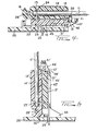
- the modified connector shown in Figure 5 is closely similar to the connector of Figures 1 to 4 and similar parts are indicated by primed reference numerals.
- the base is adapted to upstand from the printed circuit board by the provision of feet 48 extending transversely from opposite lateral edges of the base.
Landscapes
- Details Of Connecting Devices For Male And Female Coupling (AREA)
- Coupling Device And Connection With Printed Circuit (AREA)
Priority Applications (1)
| Application Number | Priority Date | Filing Date | Title |
|---|---|---|---|
| AT82303820T ATE20291T1 (de) | 1981-08-20 | 1982-07-21 | Elektrischer verbinder fuer flachkabel. |
Applications Claiming Priority (4)
| Application Number | Priority Date | Filing Date | Title |
|---|---|---|---|
| US294675 | 1981-08-20 | ||
| US06/294,675 US4426125A (en) | 1980-11-05 | 1981-08-20 | Flat cable electrical connector |
| US364152 | 1982-03-31 | ||
| US06/364,152 US4455058A (en) | 1982-03-31 | 1982-03-31 | Electrical connector for flat cable |
Publications (2)
| Publication Number | Publication Date |
|---|---|
| EP0073098A1 true EP0073098A1 (de) | 1983-03-02 |
| EP0073098B1 EP0073098B1 (de) | 1986-06-04 |
Family
ID=26968656
Family Applications (1)
| Application Number | Title | Priority Date | Filing Date |
|---|---|---|---|
| EP82303820A Expired EP0073098B1 (de) | 1981-08-20 | 1982-07-21 | Elektrischer Verbinder für Flachkabel |
Country Status (4)
| Country | Link |
|---|---|
| EP (1) | EP0073098B1 (de) |
| BR (1) | BR8204346A (de) |
| DE (2) | DE3271542D1 (de) |
| MY (1) | MY8800072A (de) |
Cited By (8)
| Publication number | Priority date | Publication date | Assignee | Title |
|---|---|---|---|---|
| GB2136642A (en) * | 1983-03-14 | 1984-09-19 | Bicc Plc | Electrical connector |
| DE3333973A1 (de) * | 1983-09-20 | 1985-04-04 | Siemens AG, 1000 Berlin und 8000 München | Kontaktklemme fuer leiterplatten |
| AT380355B (de) * | 1983-10-17 | 1986-05-12 | Hirsch Hermann Leder Kunstst | Informationssystem |
| EP0360957A3 (en) * | 1988-09-29 | 1990-10-31 | Quante Aktiengesellschaft | Connecting box for electrical lines |
| DE4034385A1 (de) * | 1990-10-29 | 1992-04-30 | Kloeckner Moeller Gmbh | Kontaktanschlussverbinder fuer mehradrige flachbandleitungen |
| WO1999060668A1 (en) * | 1998-05-20 | 1999-11-25 | Matson Automotive Industries Pty. Ltd. | Cable connection device and method |
| WO1999065112A1 (de) * | 1998-06-08 | 1999-12-16 | Siemens Aktiengesellschaft | Leiterabschlussmodul |
| WO2014086389A1 (de) * | 2012-12-03 | 2014-06-12 | Siemens Aktiengesellschaft | Modul, insbesondere für befehls- und meldegeräte |
Families Citing this family (1)
| Publication number | Priority date | Publication date | Assignee | Title |
|---|---|---|---|---|
| DE19825628C1 (de) * | 1998-06-08 | 1999-09-09 | Siemens Ag | Anschlußklemme |
Citations (7)
| Publication number | Priority date | Publication date | Assignee | Title |
|---|---|---|---|---|
| FR1304823A (fr) * | 1960-11-04 | 1962-09-28 | Bendix Corp | Connecteur électrique |
| FR1324140A (fr) * | 1961-06-05 | 1963-04-12 | Burndy Corp | Perfectionnement aux pièces de connexion pour câbles |
| GB1214316A (en) * | 1967-11-03 | 1970-12-02 | Nat Res Dev | Improvements in or relating to flat strip cable connectors |
| US3576518A (en) * | 1968-11-07 | 1971-04-27 | Minnesota Mining & Mfg | Solderless connector for insulated wires |
| US3879099A (en) * | 1973-09-04 | 1975-04-22 | Amp Inc | Flat fexible cable connector assembly including insulation piercing contacts |
| US4196956A (en) * | 1975-09-02 | 1980-04-08 | Harvey Hubbell, Incorporated | Dead-front electrical connector |
| GB2091955A (en) * | 1981-01-23 | 1982-08-04 | Legrand Sa | Electrical connector for insulated conductors |
-
1982
- 1982-07-21 EP EP82303820A patent/EP0073098B1/de not_active Expired
- 1982-07-21 DE DE8282303820T patent/DE3271542D1/de not_active Expired
- 1982-07-26 BR BR8204346A patent/BR8204346A/pt not_active IP Right Cessation
- 1982-07-26 DE DE8221251U patent/DE8221251U1/de not_active Expired
-
1988
- 1988-12-30 MY MY72/88A patent/MY8800072A/xx unknown
Patent Citations (7)
| Publication number | Priority date | Publication date | Assignee | Title |
|---|---|---|---|---|
| FR1304823A (fr) * | 1960-11-04 | 1962-09-28 | Bendix Corp | Connecteur électrique |
| FR1324140A (fr) * | 1961-06-05 | 1963-04-12 | Burndy Corp | Perfectionnement aux pièces de connexion pour câbles |
| GB1214316A (en) * | 1967-11-03 | 1970-12-02 | Nat Res Dev | Improvements in or relating to flat strip cable connectors |
| US3576518A (en) * | 1968-11-07 | 1971-04-27 | Minnesota Mining & Mfg | Solderless connector for insulated wires |
| US3879099A (en) * | 1973-09-04 | 1975-04-22 | Amp Inc | Flat fexible cable connector assembly including insulation piercing contacts |
| US4196956A (en) * | 1975-09-02 | 1980-04-08 | Harvey Hubbell, Incorporated | Dead-front electrical connector |
| GB2091955A (en) * | 1981-01-23 | 1982-08-04 | Legrand Sa | Electrical connector for insulated conductors |
Cited By (9)
| Publication number | Priority date | Publication date | Assignee | Title |
|---|---|---|---|---|
| GB2136642A (en) * | 1983-03-14 | 1984-09-19 | Bicc Plc | Electrical connector |
| DE3333973A1 (de) * | 1983-09-20 | 1985-04-04 | Siemens AG, 1000 Berlin und 8000 München | Kontaktklemme fuer leiterplatten |
| AT380355B (de) * | 1983-10-17 | 1986-05-12 | Hirsch Hermann Leder Kunstst | Informationssystem |
| EP0360957A3 (en) * | 1988-09-29 | 1990-10-31 | Quante Aktiengesellschaft | Connecting box for electrical lines |
| DE4034385A1 (de) * | 1990-10-29 | 1992-04-30 | Kloeckner Moeller Gmbh | Kontaktanschlussverbinder fuer mehradrige flachbandleitungen |
| WO1999060668A1 (en) * | 1998-05-20 | 1999-11-25 | Matson Automotive Industries Pty. Ltd. | Cable connection device and method |
| GB2351856A (en) * | 1998-05-20 | 2001-01-10 | Matson Automotive Ind Pty Ltd | Cable connection device and method |
| WO1999065112A1 (de) * | 1998-06-08 | 1999-12-16 | Siemens Aktiengesellschaft | Leiterabschlussmodul |
| WO2014086389A1 (de) * | 2012-12-03 | 2014-06-12 | Siemens Aktiengesellschaft | Modul, insbesondere für befehls- und meldegeräte |
Also Published As
| Publication number | Publication date |
|---|---|
| DE8221251U1 (de) | 1983-01-27 |
| DE3271542D1 (en) | 1986-07-10 |
| MY8800072A (en) | 1988-12-31 |
| EP0073098B1 (de) | 1986-06-04 |
| BR8204346A (pt) | 1983-07-19 |
Similar Documents
| Publication | Publication Date | Title |
|---|---|---|
| KR100212925B1 (ko) | 납작 케이블용 무삽입력 전기 커넥터 | |
| US6471541B2 (en) | Electrical connector for flat cables | |
| EP0561288B1 (de) | Leiterplatten-Klemmverbinder | |
| KR100373597B1 (ko) | 커넥터에 접속되어 있는 박판형 물체와 평행한 방향의접촉편에 결합된 회전식 액추에이터를 가지는 커넥터 | |
| CN101494336B (zh) | 电缆连接器组件 | |
| US4927787A (en) | Unitarily molded electrical connector housing with separable key | |
| US6162083A (en) | Electrical connector system for flat circuitry | |
| US5240430A (en) | Electrical connector for cable to circit board application | |
| US4455058A (en) | Electrical connector for flat cable | |
| US4232926A (en) | Locking mechanism for coupling and uncoupling electrical connectors | |
| US4405193A (en) | Preloaded electrical connector | |
| US7445494B2 (en) | Electrical connector with retaining member | |
| US5934932A (en) | Electrical connector for flat cables | |
| US4169647A (en) | Integral low profile latch for a flat cable connector | |
| US4749370A (en) | Cable clamp for an electrical connector | |
| US5921785A (en) | Electrical connector for flat cables | |
| US4174877A (en) | Connector for flat cable | |
| EP0540260A2 (de) | Elektrischer Verbinder zur Verbindung einer Leiterplatte mit einem Kabel | |
| US5921808A (en) | Ribbon cable plug-in connector | |
| EP0122486B1 (de) | Elektrischer Steckverbinder mit Quasi-Steckstiften | |
| US5775938A (en) | Connector for flat cables | |
| EP0073098B1 (de) | Elektrischer Verbinder für Flachkabel | |
| US4148537A (en) | Zero insertion force connector for printed circuit boards | |
| US4494813A (en) | Electric connector assembly | |
| EP0747996A2 (de) | Flachkabelsteckverbinder |
Legal Events
| Date | Code | Title | Description |
|---|---|---|---|
| PUAI | Public reference made under article 153(3) epc to a published international application that has entered the european phase |
Free format text: ORIGINAL CODE: 0009012 |
|
| AK | Designated contracting states |
Designated state(s): AT BE CH DE FR GB IT LI NL SE |
|
| 17P | Request for examination filed |
Effective date: 19830728 |
|
| ITF | It: translation for a ep patent filed | ||
| GRAA | (expected) grant |
Free format text: ORIGINAL CODE: 0009210 |
|
| AK | Designated contracting states |
Kind code of ref document: B1 Designated state(s): AT BE CH DE FR GB IT LI NL SE |
|
| REF | Corresponds to: |
Ref document number: 20291 Country of ref document: AT Date of ref document: 19860615 Kind code of ref document: T |
|
| REF | Corresponds to: |
Ref document number: 3271542 Country of ref document: DE Date of ref document: 19860710 |
|
| ET | Fr: translation filed | ||
| PLBE | No opposition filed within time limit |
Free format text: ORIGINAL CODE: 0009261 |
|
| STAA | Information on the status of an ep patent application or granted ep patent |
Free format text: STATUS: NO OPPOSITION FILED WITHIN TIME LIMIT |
|
| 26N | No opposition filed | ||
| ITTA | It: last paid annual fee | ||
| REG | Reference to a national code |
Ref country code: GB Ref legal event code: 732E |
|
| EAL | Se: european patent in force in sweden |
Ref document number: 82303820.3 |
|
| PGFP | Annual fee paid to national office [announced via postgrant information from national office to epo] |
Ref country code: AT Payment date: 19950621 Year of fee payment: 14 |
|
| PGFP | Annual fee paid to national office [announced via postgrant information from national office to epo] |
Ref country code: BE Payment date: 19950807 Year of fee payment: 14 |
|
| PGFP | Annual fee paid to national office [announced via postgrant information from national office to epo] |
Ref country code: CH Payment date: 19951024 Year of fee payment: 14 |
|
| PGFP | Annual fee paid to national office [announced via postgrant information from national office to epo] |
Ref country code: SE Payment date: 19960624 Year of fee payment: 15 |
|
| PGFP | Annual fee paid to national office [announced via postgrant information from national office to epo] |
Ref country code: FR Payment date: 19960715 Year of fee payment: 15 |
|
| PG25 | Lapsed in a contracting state [announced via postgrant information from national office to epo] |
Ref country code: AT Effective date: 19960721 |
|
| PG25 | Lapsed in a contracting state [announced via postgrant information from national office to epo] |
Ref country code: LI Effective date: 19960731 Ref country code: CH Effective date: 19960731 Ref country code: BE Effective date: 19960731 |
|
| BERE | Be: lapsed |
Owner name: AMP INC. (UNE SOC. DE PENNSYLVANIE) Effective date: 19960731 |
|
| REG | Reference to a national code |
Ref country code: CH Ref legal event code: PL |
|
| PG25 | Lapsed in a contracting state [announced via postgrant information from national office to epo] |
Ref country code: SE Effective date: 19970722 |
|
| PG25 | Lapsed in a contracting state [announced via postgrant information from national office to epo] |
Ref country code: FR Free format text: LAPSE BECAUSE OF NON-PAYMENT OF DUE FEES Effective date: 19980331 |
|
| EUG | Se: european patent has lapsed |
Ref document number: 82303820.3 |
|
| REG | Reference to a national code |
Ref country code: FR Ref legal event code: ST |
|
| PGFP | Annual fee paid to national office [announced via postgrant information from national office to epo] |
Ref country code: NL Payment date: 19980623 Year of fee payment: 17 |
|
| PGFP | Annual fee paid to national office [announced via postgrant information from national office to epo] |
Ref country code: GB Payment date: 19990614 Year of fee payment: 18 |
|
| PG25 | Lapsed in a contracting state [announced via postgrant information from national office to epo] |
Ref country code: NL Free format text: LAPSE BECAUSE OF NON-PAYMENT OF DUE FEES Effective date: 20000201 |
|
| NLV4 | Nl: lapsed or anulled due to non-payment of the annual fee |
Effective date: 20000201 |
|
| PG25 | Lapsed in a contracting state [announced via postgrant information from national office to epo] |
Ref country code: GB Free format text: LAPSE BECAUSE OF NON-PAYMENT OF DUE FEES Effective date: 20000721 |
|
| GBPC | Gb: european patent ceased through non-payment of renewal fee |
Effective date: 20000721 |
|
| PGFP | Annual fee paid to national office [announced via postgrant information from national office to epo] |
Ref country code: DE Payment date: 20010731 Year of fee payment: 20 |