EP0747996A2 - Flachkabelsteckverbinder - Google Patents
Flachkabelsteckverbinder Download PDFInfo
- Publication number
- EP0747996A2 EP0747996A2 EP96108130A EP96108130A EP0747996A2 EP 0747996 A2 EP0747996 A2 EP 0747996A2 EP 96108130 A EP96108130 A EP 96108130A EP 96108130 A EP96108130 A EP 96108130A EP 0747996 A2 EP0747996 A2 EP 0747996A2
- Authority
- EP
- European Patent Office
- Prior art keywords
- housing
- pressure member
- flat cable
- electrical connector
- cable
- Prior art date
- Legal status (The legal status is an assumption and is not a legal conclusion. Google has not performed a legal analysis and makes no representation as to the accuracy of the status listed.)
- Withdrawn
Links
Images


Classifications
-
- H—ELECTRICITY
- H01—ELECTRIC ELEMENTS
- H01R—ELECTRICALLY-CONDUCTIVE CONNECTIONS; STRUCTURAL ASSOCIATIONS OF A PLURALITY OF MUTUALLY-INSULATED ELECTRICAL CONNECTING ELEMENTS; COUPLING DEVICES; CURRENT COLLECTORS
- H01R13/00—Details of coupling devices of the kinds covered by groups H01R12/70 or H01R24/00 - H01R33/00
- H01R13/58—Means for relieving strain on wire connection, e.g. cord grip, for avoiding loosening of connections between wires and terminals within a coupling device terminating a cable
- H01R13/582—Means for relieving strain on wire connection, e.g. cord grip, for avoiding loosening of connections between wires and terminals within a coupling device terminating a cable the cable being clamped between assembled parts of the housing
- H01R13/5829—Means for relieving strain on wire connection, e.g. cord grip, for avoiding loosening of connections between wires and terminals within a coupling device terminating a cable the cable being clamped between assembled parts of the housing the clamping part being flexibly or hingedly connected to the housing
-
- H—ELECTRICITY
- H01—ELECTRIC ELEMENTS
- H01R—ELECTRICALLY-CONDUCTIVE CONNECTIONS; STRUCTURAL ASSOCIATIONS OF A PLURALITY OF MUTUALLY-INSULATED ELECTRICAL CONNECTING ELEMENTS; COUPLING DEVICES; CURRENT COLLECTORS
- H01R12/00—Structural associations of a plurality of mutually-insulated electrical connecting elements, specially adapted for printed circuits, e.g. printed circuit boards [PCB], flat or ribbon cables, or like generally planar structures, e.g. terminal strips, terminal blocks; Coupling devices specially adapted for printed circuits, flat or ribbon cables, or like generally planar structures; Terminals specially adapted for contact with, or insertion into, printed circuits, flat or ribbon cables, or like generally planar structures
- H01R12/70—Coupling devices
- H01R12/77—Coupling devices for flexible printed circuits, flat or ribbon cables or like structures
- H01R12/79—Coupling devices for flexible printed circuits, flat or ribbon cables or like structures connecting to rigid printed circuits or like structures
-
- H—ELECTRICITY
- H01—ELECTRIC ELEMENTS
- H01R—ELECTRICALLY-CONDUCTIVE CONNECTIONS; STRUCTURAL ASSOCIATIONS OF A PLURALITY OF MUTUALLY-INSULATED ELECTRICAL CONNECTING ELEMENTS; COUPLING DEVICES; CURRENT COLLECTORS
- H01R12/00—Structural associations of a plurality of mutually-insulated electrical connecting elements, specially adapted for printed circuits, e.g. printed circuit boards [PCB], flat or ribbon cables, or like generally planar structures, e.g. terminal strips, terminal blocks; Coupling devices specially adapted for printed circuits, flat or ribbon cables, or like generally planar structures; Terminals specially adapted for contact with, or insertion into, printed circuits, flat or ribbon cables, or like generally planar structures
- H01R12/70—Coupling devices
- H01R12/82—Coupling devices connected with low or zero insertion force
- H01R12/85—Coupling devices connected with low or zero insertion force contact pressure producing means, contacts activated after insertion of printed circuits or like structures
- H01R12/88—Coupling devices connected with low or zero insertion force contact pressure producing means, contacts activated after insertion of printed circuits or like structures acting manually by rotating or pivoting connector housing parts
-
- H—ELECTRICITY
- H01—ELECTRIC ELEMENTS
- H01R—ELECTRICALLY-CONDUCTIVE CONNECTIONS; STRUCTURAL ASSOCIATIONS OF A PLURALITY OF MUTUALLY-INSULATED ELECTRICAL CONNECTING ELEMENTS; COUPLING DEVICES; CURRENT COLLECTORS
- H01R12/00—Structural associations of a plurality of mutually-insulated electrical connecting elements, specially adapted for printed circuits, e.g. printed circuit boards [PCB], flat or ribbon cables, or like generally planar structures, e.g. terminal strips, terminal blocks; Coupling devices specially adapted for printed circuits, flat or ribbon cables, or like generally planar structures; Terminals specially adapted for contact with, or insertion into, printed circuits, flat or ribbon cables, or like generally planar structures
- H01R12/70—Coupling devices
- H01R12/77—Coupling devices for flexible printed circuits, flat or ribbon cables or like structures
- H01R12/771—Details
- H01R12/774—Retainers
Definitions
- This invention generally relates to the art of electrical connectors and, particularly, to an electrical connector for terminating a flat cable, such as a flat flexible cable, printed circuit board or the like, without requiring any insertion force.
- actuators or pressure members which are rotatably or pivotally mounted on the housing for movement between first, open positions allowing free insertion of the cables into the connector housings, and second, closed positions for clamping the flat cables against the contact portions of the terminals.
- One of the problems with prior connectors having rotatable actuators or pressure members is the tendency of moving the pressure member back toward its open position when undesired external forces are applied to the flexible flat cable.
- the flat cable tends to raise and rotate the pressure member, thereby releasing the flat cable from the connector.
- the present invention is directed to solving this problem and preventing undesired releasing or decoupling of the flat cable from the connector when certain external forces are applied to the cable.
- An object, therefore, of the invention is to provide a new and improved zero insertion force electrical connector for flat electrical cables, of the character described.
- the electrical connector includes a dielectric housing mounting a plurality of terminals in a generally parallel array transversely of the connector.
- the housing has opposite sides and a front end, with an opening between the sides for receiving an end of the flat cable in engagement with contact portions of the terminals.
- a pressure member is rotatably mounted on the housing for movement between a first position allowing insertion of the flat cable into the opening and a second position pressing conductors of the flat cable against the contact portions of the terminals.
- stop means are provided on the housing to prevent release of the flat cable from the electrical connector in the event undesired external forces are applied to the cable which would tend to bias the pressure member back toward its first position.
- the stop means are provided by overhanging extensions projecting inwardly from the opposite sides of the housing.
- the pressure member includes an actuating portion having a width sized to fit between the overhanging extensions at the opposite sides of the housing.
- a pair of pivots rotatably mount the pressure member on the housing at opposite sides of the pressure member. The pivots are located rearwardly of the overhanging extensions.
- the pressure member includes a stepped lower surface at the front thereof defining a generally triangular space between the pressure member and the flat cable when the pressure member is in its second position.
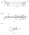
- Figure 1 shows a first embodiment of a flexible flat cable connector according to the invention.
- the connector includes a housing 1 mounting a plurality of terminals 2 in a generally parallel array.
- the housing rotatably mounts an actuator or cable pressure member 3. Details of the housing are shown in Figures 2-4, and details of the cable pressure member are shown in Figures 5-10.
- housing 1 is unitarily molded of dielectric material such as plastic or the like.
- the housing includes a base 5 having a plurality of terminal slots 4 formed therein, opposite side walls 6 molded integrally to opposite lateral edges of base 5, and a top wall 7 extending transversely between opposite side walls 6.
- Each side wall has a cam slot or track 9 facing upwardly toward top wall 7.
- cable pressure member 3 has a counter cam on each opposite side thereof for cooperating with cam slot 9 for guiding the cable pressure member between its rotatable positions.
- top wall 7 extends short of the front end of housing 1, thereby leaving a space or opening 8 at the front of the housing.
- the opening coincides with a cable insertion opening, generally designated 21, into which a flexible flat cable 22 can be inserted in the direction of arrow 23 (Fig. 3).
- housing 1 includes stop means in the form of a pair of overhanging extensions 24 projecting inwardly from opposite side walls 6 and overhanging the opposite edges 22a of flexible flat cable 22 as best seen in Figure 3.
- Each terminal 2 is stamped from sheet metal material in a bifurcated shape as best seen in Figure 1.
- the bifurcated shape defines a relatively short upper support leg 10 and a relatively long lower contact leg 11.
- Support leg 10 has a barb 12, and the terminal is fixed in a respective one of the terminal slots 4 by barb 12 of support leg 10 biting into an intermediate shelf 1a of the housing.
- Contact leg 11 has a contact portion 13 projecting from the free end of the leg upwardly toward support leg 10.
- An L-shaped soldering tail 14 extends rearwardly of the terminal and outwardly of housing 1. The bottom of the L-shaped soldering tail 14 is flush with the bottom surface of base 5 of the housing for soldering to a circuit trace on an appropriate printed circuit board.
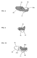
- cable pressure member 3 is unitarily molded of dielectric material, such as plastic or the like.
- the pressure member includes a major flat plate 15 which is wide enough to span the opening 8 at the front of housing 1.
- Triangular flanges 16 are molded integrally at opposite sides of flat plate 15. Each triangular flange 16 has a counter cam 17 at the front thereof. Each triangular flange 16 is positioned so that its counter cam 17 confronts the cam slot or track 9 (Fig. 4) in a respective one of the side walls of the housing.
- Major flat plate 15 of cable pressure member 3 has a width sized to fit in the space between the opposite overhanging extensions 24 of housing 1 as the cable pressure member moves from a first open position allowing insertion of flat cable 22 into opening 8 in the housing, and a second closed position pressing conductors of the flat cable against contact portions 13 of terminals 2 as shown in Figure 1.
- major flat plate 15 of cable pressure member 3 has a stepped lower surface 25 at the front thereof.
- the cable pressure member has projections 18 (Figs. 5-7) projecting outwardly of its opposite sides. Each projection 18 fits into an L-shaped slot 19 (Fig. 2) in the inner surface of one of the side walls 6 of the housing.
- the cable pressure member also has rounded side projections 20 which form detents to snap over the inside edges of overhanging extensions 24 when the pressure member is moved between its open and closed positions.
- Cam slots or tracks 9 on housing 1 and counter cams 17 on cable pressure member 3 cooperate functionally to guide the cable pressure between its rotatable positions. Specifically, when the cable pressure member is moved toward its closed position shown in Figure 1, a rear end 15a (Fig. 8) of the cable pressure member moves under a comb-like support arrangement defined by the bottom surfaces 26 (Fig. 1) of support legs 10 of terminals 2. By this action, flat cable 22 is pinched between the undersurface of the cable pressure member and contact portions 13 of terminals 2.
- housing 1 is provided with cam slots 9 and cable pressure member 3 is provided with counter cams 17 for assuring a smooth rotation and displacement of the cable pressure member toward its closed, cable pinching position.
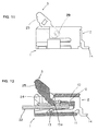
- cam means can be omitted as shown in the embodiment of Figures 11 and 12.
- pressure member 3 in Figures 11 and 12 is movable from its open position, as shown, about pivots 29 between opposite sides of the cable pressure member and the insides of the side walls of the housing, but no cam means are provided.
- soldering tails 14 of terminals 2 may comprise pin-like projections for insertion into appropriate holes in a printed circuit board and for soldering to appropriate circuit traces on the board and/or in the holes.
Landscapes
- Coupling Device And Connection With Printed Circuit (AREA)
Applications Claiming Priority (2)
| Application Number | Priority Date | Filing Date | Title |
|---|---|---|---|
| JP1995006643U JP3019288U (ja) | 1995-06-08 | 1995-06-08 | 平型柔軟ケーブル用電気コネクタ |
| JP6643/95U | 1995-06-08 |
Publications (2)
| Publication Number | Publication Date |
|---|---|
| EP0747996A2 true EP0747996A2 (de) | 1996-12-11 |
| EP0747996A3 EP0747996A3 (de) | 1997-10-01 |
Family
ID=11644057
Family Applications (1)
| Application Number | Title | Priority Date | Filing Date |
|---|---|---|---|
| EP96108130A Withdrawn EP0747996A3 (de) | 1995-06-08 | 1996-05-22 | Flachkabelsteckverbinder |
Country Status (5)
| Country | Link |
|---|---|
| US (1) | US5895287A (de) |
| EP (1) | EP0747996A3 (de) |
| JP (1) | JP3019288U (de) |
| SG (1) | SG72694A1 (de) |
| TW (1) | TW363794U (de) |
Cited By (5)
| Publication number | Priority date | Publication date | Assignee | Title |
|---|---|---|---|---|
| GB2330244A (en) * | 1997-07-30 | 1999-04-14 | Whitaker Corp | Flexible card connector |
| EP0895320A3 (de) * | 1997-07-29 | 2000-03-01 | Hirose Electric Co., Ltd. | Elektrischer Verbinder für flexible Leiterplatte |
| SG97172A1 (en) * | 1999-12-17 | 2003-07-18 | Connector Systems Tech Nv | Connector for a flat cable |
| CN112290251A (zh) * | 2020-09-14 | 2021-01-29 | 泰州市航宇电器有限公司 | 一种小型化贴装大电流连接器 |
| US11936129B2 (en) | 2021-01-14 | 2024-03-19 | Te Connectivity Germany Gmbh | Ribbon cable connector with a clamping device |
Families Citing this family (9)
| Publication number | Priority date | Publication date | Assignee | Title |
|---|---|---|---|---|
| JPH118025A (ja) * | 1997-06-16 | 1999-01-12 | Amp Japan Ltd | 回路装置 |
| US6210210B1 (en) | 2000-02-17 | 2001-04-03 | Methode Electronics, Inc. | Flat conductor termination device |
| JP3446136B2 (ja) | 2000-06-05 | 2003-09-16 | モレックス インコーポレーテッド | 電気コネクタ |
| TW582631U (en) * | 2003-06-27 | 2004-04-01 | Hon Hai Prec Ind Co Ltd | Electrical connector |
| TWM250340U (en) * | 2003-08-01 | 2004-11-11 | Hon Hai Prec Ind Co Ltd | Electrical connector |
| CN2718819Y (zh) * | 2004-06-23 | 2005-08-17 | 富士康(昆山)电脑接插件有限公司 | 柔性印刷电路连接器 |
| US20070054558A1 (en) * | 2005-09-03 | 2007-03-08 | Harlan Tod M | Connector with improved pulling portion |
| US7727006B1 (en) * | 2009-07-23 | 2010-06-01 | Cheng Uei Precision Industry Co., Ltd. | Connector for flexible printed circuit board |
| CN104904070B (zh) * | 2012-12-11 | 2018-11-13 | 诺基亚技术有限公司 | 提供用于接触柔性平坦连接件的插座触点的装置和方法 |
Family Cites Families (15)
| Publication number | Priority date | Publication date | Assignee | Title |
|---|---|---|---|---|
| US4477137A (en) * | 1982-08-23 | 1984-10-16 | Allied Corporation | Zero insertion force connector for flat cable |
| US4630874A (en) * | 1985-06-20 | 1986-12-23 | Amp Incorporated | Zero insertion force electrical interconnection assembly |
| US4639063A (en) * | 1985-12-20 | 1987-01-27 | Amp Incorporated | Electrical connector for flexible film circuits |
| JPS63274074A (ja) * | 1987-05-01 | 1988-11-11 | アンプ インコ−ポレ−テツド | 電気コンタクトアセンブリおよびその製造方法 |
| JPH088550Y2 (ja) * | 1988-01-14 | 1996-03-06 | アンプ インコーポレーテッド | フラットケーブル用コネクタ |
| DE3822980A1 (de) * | 1988-07-07 | 1990-01-11 | Lumberg Karl Gmbh & Co | Verbinder zum anschluss flacher elektrischer leiter |
| JPH0286080A (ja) * | 1988-09-21 | 1990-03-27 | Nippon Burndy Kk | フラットケーブル用コネクタ |
| JP2764647B2 (ja) * | 1990-06-29 | 1998-06-11 | 蛇の目ミシン工業株式会社 | 刺繍縫い可能なミシン |
| JPH0724230B2 (ja) * | 1990-10-25 | 1995-03-15 | 京セラエルコ株式会社 | 無挿抜力コネクタ |
| JPH069152B2 (ja) * | 1991-06-18 | 1994-02-02 | モレックス インコーポレーテッド | 水平基板接続用カードエッヂコネクタ及びその製法 |
| DE4141376C2 (de) * | 1991-12-14 | 1993-12-02 | Hirschmann Richard Gmbh Co | Foliensteckverbinder |
| TW233382B (de) * | 1993-04-02 | 1994-11-01 | Hirose Electric Co Ltd | |
| JP2820855B2 (ja) * | 1993-04-07 | 1998-11-05 | トーマス アンド ベッツ コーポレーション | コネクタ |
| JPH0722129A (ja) * | 1993-07-05 | 1995-01-24 | Kiyousera Elco Kk | Lcdコネクタ装置 |
| JP2892945B2 (ja) * | 1994-08-05 | 1999-05-17 | ヒロセ電機株式会社 | フレキシブル基板用電気コネクタ |
-
1995
- 1995-06-08 JP JP1995006643U patent/JP3019288U/ja not_active Expired - Lifetime
-
1996
- 1996-04-23 TW TW086210898U patent/TW363794U/zh unknown
- 1996-05-14 US US08/647,501 patent/US5895287A/en not_active Expired - Fee Related
- 1996-05-22 EP EP96108130A patent/EP0747996A3/de not_active Withdrawn
- 1996-06-07 SG SG1996010012A patent/SG72694A1/en unknown
Cited By (5)
| Publication number | Priority date | Publication date | Assignee | Title |
|---|---|---|---|---|
| EP0895320A3 (de) * | 1997-07-29 | 2000-03-01 | Hirose Electric Co., Ltd. | Elektrischer Verbinder für flexible Leiterplatte |
| GB2330244A (en) * | 1997-07-30 | 1999-04-14 | Whitaker Corp | Flexible card connector |
| SG97172A1 (en) * | 1999-12-17 | 2003-07-18 | Connector Systems Tech Nv | Connector for a flat cable |
| CN112290251A (zh) * | 2020-09-14 | 2021-01-29 | 泰州市航宇电器有限公司 | 一种小型化贴装大电流连接器 |
| US11936129B2 (en) | 2021-01-14 | 2024-03-19 | Te Connectivity Germany Gmbh | Ribbon cable connector with a clamping device |
Also Published As
| Publication number | Publication date |
|---|---|
| JP3019288U (ja) | 1995-12-12 |
| EP0747996A3 (de) | 1997-10-01 |
| SG72694A1 (en) | 2000-05-23 |
| TW363794U (en) | 1999-07-01 |
| US5895287A (en) | 1999-04-20 |
Similar Documents
| Publication | Publication Date | Title |
|---|---|---|
| US5695360A (en) | Zero insertion force electrical connector for flat cable | |
| US6551128B2 (en) | Connector for connecting flexible substrates | |
| US6726497B2 (en) | Connector for flat flexible cable | |
| EP0947944B1 (de) | Verbinder für Kartenleser | |
| US5240430A (en) | Electrical connector for cable to circit board application | |
| US5895287A (en) | Flat cable connector | |
| KR950003111Y1 (ko) | 플랫 전기 케이블용 전기 커넥터 | |
| JP2835563B2 (ja) | プリント回路板用のエッジコネクタ | |
| CN101536267B (zh) | 用于柔性电缆的继电器连接器 | |
| US4341429A (en) | Electrical connector | |
| US6056571A (en) | Electrical connector for flat electrical conductor | |
| US6837740B2 (en) | Flat circuit connector | |
| KR20030040125A (ko) | 평평한 가요성 케이블용 커넥터 | |
| KR20040042773A (ko) | 편평형 도체의 접속을 위한 전기 커넥터 | |
| US5934932A (en) | Electrical connector for flat cables | |
| US5921785A (en) | Electrical connector for flat cables | |
| US4332431A (en) | Preassembled electrical connector | |
| US5692920A (en) | Zero insertion force electrical connector and terminal | |
| US5791929A (en) | Zero insertion force electrical connector and terminal | |
| US5597320A (en) | Zero insertion force electrical connector and terminal | |
| US7344399B2 (en) | Flat circuit connector | |
| US5863217A (en) | Lock mechanism for FPC connector | |
| US7029319B2 (en) | Flat circuit connector | |
| US5451172A (en) | Connector for flat cables | |
| US5741154A (en) | Electrical connector for flat cable |
Legal Events
| Date | Code | Title | Description |
|---|---|---|---|
| PUAI | Public reference made under article 153(3) epc to a published international application that has entered the european phase |
Free format text: ORIGINAL CODE: 0009012 |
|
| AK | Designated contracting states |
Kind code of ref document: A2 Designated state(s): DE FR GB IT |
|
| PUAL | Search report despatched |
Free format text: ORIGINAL CODE: 0009013 |
|
| RHK1 | Main classification (correction) |
Ipc: H01R 23/68 |
|
| AK | Designated contracting states |
Kind code of ref document: A3 Designated state(s): DE FR GB IT |
|
| 17P | Request for examination filed |
Effective date: 19980224 |
|
| 17Q | First examination report despatched |
Effective date: 20000128 |
|
| RIC1 | Information provided on ipc code assigned before grant |
Free format text: 7H 01R 12/16 A, 7H 01R 12/24 B |
|
| GRAG | Despatch of communication of intention to grant |
Free format text: ORIGINAL CODE: EPIDOS AGRA |
|
| GRAG | Despatch of communication of intention to grant |
Free format text: ORIGINAL CODE: EPIDOS AGRA |
|
| GRAH | Despatch of communication of intention to grant a patent |
Free format text: ORIGINAL CODE: EPIDOS IGRA |
|
| GRAH | Despatch of communication of intention to grant a patent |
Free format text: ORIGINAL CODE: EPIDOS IGRA |
|
| STAA | Information on the status of an ep patent application or granted ep patent |
Free format text: STATUS: THE APPLICATION IS DEEMED TO BE WITHDRAWN |
|
| 18D | Application deemed to be withdrawn |
Effective date: 20021203 |