EP0073148A2 - Système de commande hydraulique - Google Patents
Système de commande hydraulique Download PDFInfo
- Publication number
- EP0073148A2 EP0073148A2 EP82304405A EP82304405A EP0073148A2 EP 0073148 A2 EP0073148 A2 EP 0073148A2 EP 82304405 A EP82304405 A EP 82304405A EP 82304405 A EP82304405 A EP 82304405A EP 0073148 A2 EP0073148 A2 EP 0073148A2
- Authority
- EP
- European Patent Office
- Prior art keywords
- valve
- fluid
- spool
- flow
- actuator
- Prior art date
- Legal status (The legal status is an assumption and is not a legal conclusion. Google has not performed a legal analysis and makes no representation as to the accuracy of the status listed.)
- Granted
Links
Images

Classifications
-
- F—MECHANICAL ENGINEERING; LIGHTING; HEATING; WEAPONS; BLASTING
- F15—FLUID-PRESSURE ACTUATORS; HYDRAULICS OR PNEUMATICS IN GENERAL
- F15B—SYSTEMS ACTING BY MEANS OF FLUIDS IN GENERAL; FLUID-PRESSURE ACTUATORS, e.g. SERVOMOTORS; DETAILS OF FLUID-PRESSURE SYSTEMS, NOT OTHERWISE PROVIDED FOR
- F15B13/00—Details of servomotor systems ; Valves for servomotor systems
- F15B13/02—Fluid distribution or supply devices characterised by their adaptation to the control of servomotors
- F15B13/04—Fluid distribution or supply devices characterised by their adaptation to the control of servomotors for use with a single servomotor
- F15B13/042—Fluid distribution or supply devices characterised by their adaptation to the control of servomotors for use with a single servomotor operated by fluid pressure
- F15B13/043—Fluid distribution or supply devices characterised by their adaptation to the control of servomotors for use with a single servomotor operated by fluid pressure with electrically-controlled pilot valves
- F15B13/0435—Fluid distribution or supply devices characterised by their adaptation to the control of servomotors for use with a single servomotor operated by fluid pressure with electrically-controlled pilot valves the pilot valves being sliding valves
-
- B—PERFORMING OPERATIONS; TRANSPORTING
- B66—HOISTING; LIFTING; HAULING
- B66B—ELEVATORS; ESCALATORS OR MOVING WALKWAYS
- B66B1/00—Control systems of elevators in general
- B66B1/24—Control systems with regulation, i.e. with retroactive action, for influencing travelling speed, acceleration, or deceleration
Definitions
- the present invention relates to hydraulic control systems.
- a hydraulic actuator In some hydraulic systems the operation of a hydraulic actuator, or actuators, is subject to two opposing forces, the first of which is provided by hydraulic fluid under pressure, the other being the result of a restoring force.
- gravity in the form of the weight of the load, or return springs may oppose the force due to the hydraulic pressure applied to move the load in one direction and, on ceasing of the pressure, act to return the load to its original position by moving it in the reverse direction.
- the rate of movement of the actuator in the first direction can be controlled by regulating the rate of fluid flow to the actuator, and in the reverse direction by regulating the rate of fluid flow returning from the actuator to tank.
- Such systems may, for example, be applied to operate hydraulic lifts.
- the present invention comprises a hydraulic system including a pilot controlled, pressure operated, spool valve which acts substantially as a by-pass valve when regulating supply of fluid to actuating means, and as an in-line valve when regulating the return flow of fluid from the actuating means to tank, and which provides both these regulating functions with a single main valve.
- the present invention thus provides a hydraulic control system of the afore-mentioned kind, in which both directions of movement can be controlled by a single valve.
- Suitable actuating means include, inter alia, cylinder actuators and reversible hydraulic motors.
- the present invention can also provide a hydraulic system in which regulation of fluid flow to the actuating means is load and temperature compensated and substantially independent of pump flow provided the pump flow reaches a predetermined minimum.
- the load and temperature compensation can be provided by including in the service line from the main valve to the actuating means a flow sensor which provides negative feedback to the pilot stage controlling the main valve in both the by-pass and the in-line mode of operation.
- the feedback may be provided hydraulically or electrically in the manner disclosed, for example, in the published European Patent Application 0 023 416 in the name of Sperry Limited.
- a further aim of the present invention is to provide a hydraulic control system which is capable of being made sufficiently reliable to fulfil the safety requirements applicable to personnel carrying lifts.
- the system may additionally incorporate a releasable non-return valve in the service line from the main valve to the actuating means.
- Releasable non-return valves are commercially available, and the valve is to be inserted into the service line such that it opens under the pressure of the fluid flowing from the valve to the actuating means, closes under the back pressure produced by the restoring force when fluid flow to the actuating means is halted, and is opened by a suitable actuating mechanism which, for instance, may itself be hydraulic and be controlled by a further hydraulic valve.
- the present invention also aims to provide a lift control system which is economical in terms of required components, or which is efficient in its use of energy or both.
- Regulating the supply of fluid to the load in a by-pass mode, rather than by in-line control, has the added advantage of permitting the use of a fixed displacement pump at near maximum efficiency.
- a fixed displacement pump is generally less complicated and therefore cheaper than a variable displacement pump of comparable performance.
- the lift will normally be propelled upwards by the pressure of the hydraulic fluid and return downwards under its own weight.
- the hydraulic actuator acts on a counter-weight to the lift, can readily be envisaged and are included in the scope of the present invention.
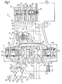
- the main components of the hydraulic system illustrated in this Figure are a main valve 2, a pilot valve 5 with attached force motor, a releasable, hydraulically operated non-return valve 7, a hydraulic actuator 8 for propelling a lift (not shown), and a further spool valve 9.
- the main valve 2 comprises a valve body 21 in which in a landed main spool 31 is housed in a main valve bore 22.
- Various ports which cooperate with the lands of the spool 31, open into the main valve bore 22. These are a supply line port 23, a service line port 24, an exhaust port 25, a tank return port 26, and a by-pass port 27. Of these, the ports 23, 25 and 26 are connected directly with their respective external ports 23', 25', 26' in the connector face plate 40 at the bottom of the main valve 2.
- the connection between the port 24 and its external port 24' is via fluid ducts 29 and 30, leading to and from a variable aperture flow sensor 20 which provides negative flow feedback.
- Supply line port 23 and by-pass port 27 are permanently connected by an internal fluid duct 28 in the valve body 21.
- the return springs, 42 and 44 located in the left and right end chambers 41 and 43 respectively of the main valve 2, act to centre the valve spool 31 within the valve bore 22.
- the two end chambers 41 and 43 are connected via lines 64 and 65 through a connector plate 6 to the pilot valve 5, whose function is to control the pressures within the two end chambers 41 and 43.
- the supply control land 32 cooperates with the supply line port 23 and the service line port 24, to enable the service line 71, and therefore the actuator 8, to be connected to and disconnected from the supply line. It should be noted that the supply control land does not obstruct free flow of fluid from the supply line port to the fluid duct 28.
- the exhaust control land 33 cooperates with the service line port 24 and the exhaust port 25, to control fluid from the service line 71 to tank.
- the rate of fluid flow to the actuator 8 is mainly regulated by the by-pass control land 34 cooperating with the tank return port 26 and the by-pass port 27. There is thus provided a variable aperture in a by-pass line to the actuator 8, from the inlet port 23 through the fluid duct 28 to tank.
- the lands 32 and 33 are shaped so as to provide, in the centre position of the spool 31 as shown in the drawing, a considerable overlap with the associated ports 23 and 25, sufficient to reduce leakage through the valve 2 to an acceptable minimum for the application concerned.
- the pilot valve 5 is also a spool valve and is controlled by a force motor 55 which operates through shaft 59 on the spool 52 of the pilot valve.
- the pilot spool 52 is housed in a pilot valve bore 51 and has three lands.
- the centre land 56 controls the amount of fluid directed from the pilot valve supply line 63 via fluid ducts 64 and 65 to the end chambers 41 and 43 respectively of the main valve 2. Those portions of the two end lands 57 and 58, which are nearest the centre land 56, cooperate in this function by controlling the proportion of fluid supplied by the pilot supply line 63, which is returned to tank via fluid line 66.
- the pilot valve spool 52 is also acted on by a pressure differential between end chambers 53 and 54, the origin of which is at the flow sensor 20.
- This pressure differential is developed by fluid flowing through the flow sensor 20 and is transmitted to the end chamber 53 via fluid line 62 branching off fluid duct 29, and to end chamber 54 via fluid line 61 branching off the fluid duct 30.
- the pressure differential between end chambers 53 and 54 is arranged to provide a negative feedback to the pilot valve.
- the main valve 2 is supplied with fluid under pressure by pump 92 and through a filter 95.
- a relief valve 97 acts as safety valve to prevent the pressure supplied to the main valve 2 from rising above a predetermined maximum.
- the pump 92 is driven by a motor 91 to which is coupled a further pump 93 which supplies the fluid supply both to the pilot valve 5 and to the releasable non-return valve 7. Fluid supply to both these valves is controlled by the spool valve 9, the function of which will be described below.
- the fluid supply to the non-return valve 7 and the pilot valve 5 is similarly provided with a filter, 96, and a relief valve 94.
- the hydraulic system just described operates as follows.
- the connection between the supply line port 23 and the service line port 24 is closed by the supply control land 32, while the connection between the supply line port 23 and the tank is, on account of the position of the by-pass control land 34, open to tank.
- the exhaust control land 33 blocks off the exhaust port 25 so that fluid is unable to flow either to or from the actuator 8, flow from the actuator 8 being additionally blocked by the releasable non-return valve 7. If it is desired to raise the piston arrangement 82 of the actuator 8 from the lowered position shown in the drawing, the main valve spool 31 needs to be moved towards the left, which is achieved by applying an appropriate demand signal to the force motor 55.
- the demand signal in this case has to be such as to cause the force motor 55 to shift the pilot spool 52 towards the left.
- fluid from the pilot supply line 63 is admitted, via fluid line 65, to the right hand chamber 43 of the main valve.
- the right hand edge of the left hand land 57 at least partially clears the port leading to the tank line 66, and the left-hand chamber 41 of the main valve is thus in communication with the tank pressure.
- the fluid flow from the service line port 24, via the fluid lines 29 and 30, to the hydraulic actuator 8 causes a pressure differential to be developed across the flow sensor 20, which increases with increasing flow.
- This pressure differential is applied via fluid line 61 from fluid duct 30, and via fluid line 62 from fluid duct 29, to the respective end chambers 53 and 54 of the pilot valve.
- the pressure differential counter-acts the force of the force motor 55 and, as the flow increases, progressively pushes the pilot spool 52 back towards the centre position shown in the drawing. During this return to the centre position, fluid flow to the right hand chamber 43, and fluid flow from the left hand chamber 41 to tank, are progressively reduced.
- the main valve spool 31 is locked in position as long as the desired flow rate is maintained. Any changes in the flow rate to the actuator 8 produces a change in the pressure differential across the pilot valve, and the pilot spool 52 moves into a new position to cause the main spool 31 to restore the desired flow.
- a change in the desired flow rate has the effect of changing the force with which the force motor 55 acts on the pilot spool 52, and again, the pilot spool 52 is moved under the combined action of the pressure differential and the force provided by the force motor 55 to adjust the flow through the main valve 2 to the desired value.
- the further spool valve 9 is shown schematically only, with the three adjacent squares corresponding to the three flow patterns which can be set up through the valve, in its left hand, centre, and right hand positions. Assuming that the lift drive is such that raising the actuator raises the lift, when the lift is to ascend, the spool valve 9 is energised to operate according to the flow pattern shown in the left square, that is to say, fluid from pump 93 is admitted to the pilot supply line 63, and the hydraulic actuator of the releasable non-return valve 7 is connected to tank.
- the demand signal to the force motor 55 becomes such as to cause a return of the main valve spool 31 to its centre position. Returning the main spool 31 to the centre position will shut off flow to the actuator 8 and once again open the by-pass line fully to the tank return port 26. Fluid from the pump 92 therefore, freely passes through the valve with only a minimal pressure drop, and as a result the pump 92 is substantially off-loaded. At the same time fluid is prevented from returning from the actuator 8 to tank, firstly by the non-return valve 7, and secondly by the positon of the land 33, which prevents fluid flow from the service line port 24 to the exhaust port 25.
- the spool valve 9 is moved into the position indicated by the right hand side of the three flow patterns.
- the actuator (not shown) of the release valve 7 opens the release valve 7, and at the same time fluid supply to the pilot valve 5 via fluid supply line 63 is re-established.
- the demand signal to the force motor is now selected to move the pilot spool towards the right.
- the main valve spool 31 is also shifted to the right.
- the by-pass path from the supply line port 23, through the internal passage 28, and the by-pass port 27 to the tank port 26, is still unobstructed and a connection between service line port 24 and exhaust port 25 is established on account of the right shift of the land 33.
- Fluid is thus allowed to drain, in a controlled manner, from the actuator 8 via the service line 71, the non-return valve 7, the fluid lines 30, 29 and the service line port 24 to the exhaust port 25, and hence to tank.
- This fluid flow will once again result in a pressure differential being developed across the flow sensor 20, but this pressure differential will be in the opposite direction to that established during the ascent of the lift.
- this feedback pressure differential will once again tend to counter-act the force on the pilot spool 62 from the force motor 55 and to restore the pilot spool 52 to its centre position.
- the spool valve 9 may, if desired, be replaced by two independently operable valves, one to control fluid supply to the pilot valve 5, the other to control actuation of the non-return valve 7. In certain circumstances the latter arrangement may be more convenient, for instance to achieve a suitable timing sequence for the main, pilot, and non-return valves which cannot be obtained with a single spool valve 9.
- Figure 2 shows schematically an alternative lay-out of the ports and lands of the main valve. Since the configuration and interaction of the remaining components such as, for instance, the non-return valve 7, the spool valve 9, the pilot valve etc., is practically identical to that of Figure 1, these components, have been omitted from Figure 2 for the sake of convenience.
- a hydraulic system including the present invention has been described in relation to a lift system in which the lift is raised through raising the hydraulic actuator 8 by supplying fluid under pressure to the underside of the actuator piston.
- the system of the present invention will equally operate in other hydraulic lift systems in which, for instance, the actuator pulls rather than pushes the lift or, in other words, in which fluid is supplied to the topside rather than the underside of the piston.
- the invention may of course be used in systems other than lift systems, provided the actuator is subject to a restoring force which counter-acts movement of the actuator when supplied with fluid under pressure, and which, hence, tends to restore the actuator and the load to its original position.
Landscapes
- Engineering & Computer Science (AREA)
- Automation & Control Theory (AREA)
- Physics & Mathematics (AREA)
- Fluid Mechanics (AREA)
- Mechanical Engineering (AREA)
- General Engineering & Computer Science (AREA)
- Fluid-Pressure Circuits (AREA)
- Servomotors (AREA)
Applications Claiming Priority (2)
| Application Number | Priority Date | Filing Date | Title |
|---|---|---|---|
| GB8125585 | 1981-08-21 | ||
| GB8125585 | 1981-08-21 |
Publications (3)
| Publication Number | Publication Date |
|---|---|
| EP0073148A2 true EP0073148A2 (fr) | 1983-03-02 |
| EP0073148A3 EP0073148A3 (en) | 1984-05-23 |
| EP0073148B1 EP0073148B1 (fr) | 1986-11-12 |
Family
ID=10524095
Family Applications (1)
| Application Number | Title | Priority Date | Filing Date |
|---|---|---|---|
| EP82304405A Expired EP0073148B1 (fr) | 1981-08-21 | 1982-08-20 | Système de commande hydraulique |
Country Status (5)
| Country | Link |
|---|---|
| US (1) | US4667571A (fr) |
| EP (1) | EP0073148B1 (fr) |
| JP (1) | JPS5846206A (fr) |
| DE (1) | DE3274280D1 (fr) |
| ZA (1) | ZA825477B (fr) |
Cited By (1)
| Publication number | Priority date | Publication date | Assignee | Title |
|---|---|---|---|---|
| EP0265729A3 (fr) * | 1986-10-17 | 1989-05-03 | Cemcolift, Inc. | Valve de commande autoajustable pour ascenseur |
Families Citing this family (7)
| Publication number | Priority date | Publication date | Assignee | Title |
|---|---|---|---|---|
| JPS62167902A (ja) * | 1985-11-18 | 1987-07-24 | オ−チス エレベ−タ コムパニ− | 動的にプログラムしたモ−タ操作バルブ制御装置 |
| US7308848B2 (en) * | 2004-12-02 | 2007-12-18 | Sarcos Investments Lc | Pressure control valve having intrinsic feedback system |
| US7284471B2 (en) * | 2004-12-02 | 2007-10-23 | Sarcos Investments Lc | Pressure control valve having intrinsic mechanical feedback system |
| US8061261B2 (en) * | 2007-02-28 | 2011-11-22 | Raytheon Company | Antagonistic fluid control system for active and passive actuator operation |
| JP5460335B2 (ja) * | 2007-02-28 | 2014-04-02 | レイセオン カンパニー | 選択的に起動可能な作動装置を有する流体制御システム |
| US7779863B2 (en) * | 2007-06-29 | 2010-08-24 | Raytheon Sarcos, Llc | Pressure control valve having an asymmetric valving structure |
| CN105366583B (zh) * | 2015-12-15 | 2019-03-22 | 常州信息职业技术学院 | 基于无线通信的智能千斤顶装置 |
Family Cites Families (11)
| Publication number | Priority date | Publication date | Assignee | Title |
|---|---|---|---|---|
| US3878765A (en) * | 1971-01-05 | 1975-04-22 | Sperry Rand Ltd | Hydraulic actuator controls |
| GB1406326A (en) * | 1972-11-08 | 1975-09-17 | Sperry Rand Ltd | Hydraulic actuator controls disazo pigment |
| GB1462879A (en) * | 1973-10-10 | 1977-01-26 | Sperry Rand Ltd | Hydraulic actuator controls |
| US4011888A (en) * | 1976-03-12 | 1977-03-15 | Elevator Equipment Co. | Unitary elevator up level control valve |
| US4111283A (en) * | 1976-12-20 | 1978-09-05 | Clark Equipment Company | Regulator valve |
| US4411189A (en) * | 1977-07-18 | 1983-10-25 | The Scott And Fetzer Company | Fluid flow controlling device |
| US4249641A (en) * | 1978-11-14 | 1981-02-10 | Hitachi, Ltd. | Speed control system for hydraulic elevator |
| GB2050646B (en) * | 1979-06-15 | 1983-04-13 | Sperry Rand Corp | Hydraulic actuator controls |
| EP0023416B1 (fr) * | 1979-07-26 | 1985-12-27 | Vickers Incorporated | Soupape hydraulique |
| US4392415A (en) * | 1980-12-19 | 1983-07-12 | Caterpillar Tractor Co. | Control for dead engine lower |
| US4418612A (en) * | 1981-05-28 | 1983-12-06 | Vickers, Incorporated | Power transmission |
-
1982
- 1982-07-29 ZA ZA825477A patent/ZA825477B/xx unknown
- 1982-08-17 US US06/408,752 patent/US4667571A/en not_active Expired - Fee Related
- 1982-08-20 JP JP57143470A patent/JPS5846206A/ja active Pending
- 1982-08-20 EP EP82304405A patent/EP0073148B1/fr not_active Expired
- 1982-08-20 DE DE8282304405T patent/DE3274280D1/de not_active Expired
Cited By (1)
| Publication number | Priority date | Publication date | Assignee | Title |
|---|---|---|---|---|
| EP0265729A3 (fr) * | 1986-10-17 | 1989-05-03 | Cemcolift, Inc. | Valve de commande autoajustable pour ascenseur |
Also Published As
| Publication number | Publication date |
|---|---|
| JPS5846206A (ja) | 1983-03-17 |
| EP0073148A3 (en) | 1984-05-23 |
| US4667571A (en) | 1987-05-26 |
| ZA825477B (en) | 1983-06-29 |
| DE3274280D1 (en) | 1987-01-02 |
| EP0073148B1 (fr) | 1986-11-12 |
Similar Documents
| Publication | Publication Date | Title |
|---|---|---|
| US4222409A (en) | Load responsive fluid control valve | |
| CA1125145A (fr) | Transmission de puissance | |
| US4480527A (en) | Power transmission | |
| EP0085962A2 (fr) | Système hydraulique de commande en particulier pour des charges pivotantes | |
| US4418612A (en) | Power transmission | |
| US4407122A (en) | Power transmission | |
| EP0251172A2 (fr) | Système de commande hydraulique | |
| US4353289A (en) | Power transmission | |
| US4285195A (en) | Load responsive control system | |
| EP0073148B1 (fr) | Système de commande hydraulique | |
| EP0111208A1 (fr) | Transmission de puissance | |
| US4140152A (en) | Load responsive valve assemblies | |
| US4753157A (en) | Power transmission | |
| US4327627A (en) | Load responsive fluid control valve | |
| US4798126A (en) | Load responsive system using load responsive pump control of a bypass type | |
| US4293001A (en) | Load responsive fluid control valve | |
| US4362088A (en) | Load responsive fluid control valve | |
| US4293000A (en) | Load responsive fluid control valve | |
| US4267860A (en) | Load responsive valve assemblies | |
| US4199005A (en) | Load responsive control valve | |
| GB1581921A (en) | Load-responsive direction and flow control valve | |
| EP0086772B1 (fr) | Commandes de systemes sensibles a la charge | |
| EP0085674B1 (fr) | Vanne de commande de fluide sensible a la charge | |
| JPH07279908A (ja) | 油圧回路のヒート装置 | |
| JP3752153B2 (ja) | 圧力補償油圧回路 |
Legal Events
| Date | Code | Title | Description |
|---|---|---|---|
| PUAI | Public reference made under article 153(3) epc to a published international application that has entered the european phase |
Free format text: ORIGINAL CODE: 0009012 |
|
| AK | Designated contracting states |
Designated state(s): CH DE FR GB IT LI SE |
|
| PUAL | Search report despatched |
Free format text: ORIGINAL CODE: 0009013 |
|
| AK | Designated contracting states |
Designated state(s): CH DE FR GB IT LI SE |
|
| 17P | Request for examination filed |
Effective date: 19841108 |
|
| RAP1 | Party data changed (applicant data changed or rights of an application transferred) |
Owner name: VICKERS, INCORPORATED |
|
| ITF | It: translation for a ep patent filed | ||
| GRAA | (expected) grant |
Free format text: ORIGINAL CODE: 0009210 |
|
| AK | Designated contracting states |
Kind code of ref document: B1 Designated state(s): CH DE FR GB IT LI SE |
|
| REF | Corresponds to: |
Ref document number: 3274280 Country of ref document: DE Date of ref document: 19870102 |
|
| ET | Fr: translation filed | ||
| PLBE | No opposition filed within time limit |
Free format text: ORIGINAL CODE: 0009261 |
|
| STAA | Information on the status of an ep patent application or granted ep patent |
Free format text: STATUS: NO OPPOSITION FILED WITHIN TIME LIMIT |
|
| 26N | No opposition filed | ||
| PG25 | Lapsed in a contracting state [announced via postgrant information from national office to epo] |
Ref country code: GB Effective date: 19890820 |
|
| PG25 | Lapsed in a contracting state [announced via postgrant information from national office to epo] |
Ref country code: SE Effective date: 19890821 |
|
| PG25 | Lapsed in a contracting state [announced via postgrant information from national office to epo] |
Ref country code: LI Effective date: 19890831 Ref country code: CH Effective date: 19890831 |
|
| GBPC | Gb: european patent ceased through non-payment of renewal fee | ||
| PG25 | Lapsed in a contracting state [announced via postgrant information from national office to epo] |
Ref country code: FR Effective date: 19900427 |
|
| REG | Reference to a national code |
Ref country code: CH Ref legal event code: PL |
|
| PG25 | Lapsed in a contracting state [announced via postgrant information from national office to epo] |
Ref country code: DE Effective date: 19900501 |
|
| REG | Reference to a national code |
Ref country code: FR Ref legal event code: ST |
|
| EUG | Se: european patent has lapsed |
Ref document number: 82304405.2 Effective date: 19900418 |