EP0073469B1 - Hermetisch geschlossener Kompressor - Google Patents
Hermetisch geschlossener Kompressor Download PDFInfo
- Publication number
- EP0073469B1 EP0073469B1 EP82107814A EP82107814A EP0073469B1 EP 0073469 B1 EP0073469 B1 EP 0073469B1 EP 82107814 A EP82107814 A EP 82107814A EP 82107814 A EP82107814 A EP 82107814A EP 0073469 B1 EP0073469 B1 EP 0073469B1
- Authority
- EP
- European Patent Office
- Prior art keywords
- suction
- pipe
- type motor
- sealed type
- motor compressor
- Prior art date
- Legal status (The legal status is an assumption and is not a legal conclusion. Google has not performed a legal analysis and makes no representation as to the accuracy of the status listed.)
- Expired
Links
- 238000004891 communication Methods 0.000 claims description 11
- 238000005192 partition Methods 0.000 claims description 6
- 229920003002 synthetic resin Polymers 0.000 claims description 4
- 239000000057 synthetic resin Substances 0.000 claims description 4
- 230000002093 peripheral effect Effects 0.000 claims description 3
- 239000003507 refrigerant Substances 0.000 description 11
- 230000006835 compression Effects 0.000 description 3
- 238000007906 compression Methods 0.000 description 3
- 238000010276 construction Methods 0.000 description 3
- 239000003921 oil Substances 0.000 description 3
- 239000007788 liquid Substances 0.000 description 2
- 238000004804 winding Methods 0.000 description 2
- 238000004026 adhesive bonding Methods 0.000 description 1
- 238000005219 brazing Methods 0.000 description 1
- 239000010724 circulating oil Substances 0.000 description 1
- 238000001746 injection moulding Methods 0.000 description 1
- 238000003780 insertion Methods 0.000 description 1
- 230000037431 insertion Effects 0.000 description 1
- 239000000314 lubricant Substances 0.000 description 1
- 239000000463 material Substances 0.000 description 1
- 239000004033 plastic Substances 0.000 description 1
- 229920003023 plastic Polymers 0.000 description 1
- -1 polybutylene terephthalate Polymers 0.000 description 1
- 229920001707 polybutylene terephthalate Polymers 0.000 description 1
- 230000010349 pulsation Effects 0.000 description 1
- 239000010726 refrigerant oil Substances 0.000 description 1
- 238000000926 separation method Methods 0.000 description 1
Images

Classifications
-
- F—MECHANICAL ENGINEERING; LIGHTING; HEATING; WEAPONS; BLASTING
- F04—POSITIVE - DISPLACEMENT MACHINES FOR LIQUIDS; PUMPS FOR LIQUIDS OR ELASTIC FLUIDS
- F04B—POSITIVE-DISPLACEMENT MACHINES FOR LIQUIDS; PUMPS
- F04B39/00—Component parts, details, or accessories, of pumps or pumping systems specially adapted for elastic fluids, not otherwise provided for in, or of interest apart from, groups F04B25/00 - F04B37/00
- F04B39/0027—Pulsation and noise damping means
-
- F—MECHANICAL ENGINEERING; LIGHTING; HEATING; WEAPONS; BLASTING
- F04—POSITIVE - DISPLACEMENT MACHINES FOR LIQUIDS; PUMPS FOR LIQUIDS OR ELASTIC FLUIDS
- F04B—POSITIVE-DISPLACEMENT MACHINES FOR LIQUIDS; PUMPS
- F04B39/00—Component parts, details, or accessories, of pumps or pumping systems specially adapted for elastic fluids, not otherwise provided for in, or of interest apart from, groups F04B25/00 - F04B37/00
- F04B39/12—Casings; Cylinders; Cylinder heads; Fluid connections
- F04B39/123—Fluid connections
-
- Y—GENERAL TAGGING OF NEW TECHNOLOGICAL DEVELOPMENTS; GENERAL TAGGING OF CROSS-SECTIONAL TECHNOLOGIES SPANNING OVER SEVERAL SECTIONS OF THE IPC; TECHNICAL SUBJECTS COVERED BY FORMER USPC CROSS-REFERENCE ART COLLECTIONS [XRACs] AND DIGESTS
- Y10—TECHNICAL SUBJECTS COVERED BY FORMER USPC
- Y10S—TECHNICAL SUBJECTS COVERED BY FORMER USPC CROSS-REFERENCE ART COLLECTIONS [XRACs] AND DIGESTS
- Y10S417/00—Pumps
- Y10S417/902—Hermetically sealed motor pump unit
Definitions
- This invention relates to a sealed type motor compressor comprising a motor section and a compressor section resiliently supported within a sealed enclosure, a suction pipe extending through said sealed enclosure, a suction muffler provided on said compressor section, an insert pipe fitted into an inlet port of said suction muffler, and a helical spring interposed between said suction pipe and said insert pipe.
- Such compressors are used in connection with refrigerators, air conditioners and the like, and a refrigerant gas is delivered to the compressor section through the suction muffler from the suction pipe.
- a sealed enclosure is used as a low pressure vessel such that a suction refrigerant gas of low temperatures and low pressures returned through a suction pipe is temporarily stored in a space defined by the sealed enclosure and is then sucked into the suction side of a compressor section.
- a suction refrigerant gas of low temperatures and low pressures returned through a suction pipe is temporarily stored in a space defined by the sealed enclosure and is then sucked into the suction side of a compressor section.
- such temporary storage of the suction refrigerant gas in the sealed enclosure causes the gas to be exposed to heat generated from the motor section and the compressor section, so that when sucked into the compressor section, the gas becomes substantially high in temperature.
- the discharge refrigerant gas becomes correspondingly high in temperature to have a disadvantageous influence on itself as well as on a lubricant oil and other elements and to lower the volumetric efficiency of the compressor section.
- the motor compressor disclosed in US Patent No. 4,086,032 has its insert pipe tightly and rigidly arranged within the inlet port while the suction pipe has its inwardly directed opening flush with the inner wall of the sealed enclosure.
- a slidable tube is guided on the outer circumference of the insert pipe and is biased into the direction of the inner wall of the sealed enclosure in order to abut against the inner wall to thereby sealingly connect the suction pipe and the insert pipe.
- two slidable seals have to be maintained between the insert pipe and the slidable tube on the one hand and the slidable tube and the inner wall of the enclosure adjacent to the opening of the suction pipe on the other hand.
- the arrangement is complicated and liable to wear.
- liquid refrigerant and circulating oil contained in the refrigerant gas flow directly into the compressor to cause liquid compression and oil compression which can possibly be sources for great troubles such as failures of valve portions, a crank shaft and a connecting rod.
- Dyhr et al. patent proposes the provision of an oil-gas separator outside the compressor casing, which makes the apparatus large in size.
- the invention is characterized in that said helical spring is closely coiled in the form of a cylinder and interconnects said suction pipe and said insert pipe which is fitted into the inlet port with a slight clearance therebetween.
- the sealed type motor compressor according to the invention is adapted for quiet operation.
- said suction muffler is connected to said compressor section through a communication pipe which extends through an aperture of said muffler to be forcedly fitted into a suction port formed in said compressor section.
- the suction muffler is formed of a synthetic resin.
- the muffler is thus formed of a material of easy fabricability into a shape such that the mounting of the muffler is relieved from any failure due to thermal expansion.
- said suction muffler comprises a cup-shaped body formed of a synthetic resin and divided into at least two sections, a closure member adapted to cover an opening of said body, a curved partition plate formed with a through hole and resiliently interposed between said body and said closure member, apertures formed on one of said body and said closure member, and latches formed on the other of said body and said closure member and adapted for engagement with said apertures.
- the muffler is effective for oil-gas separation and is easy in assembling.
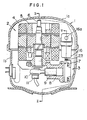
- a sealed type motor compressor according to an embodiment of the invention, which comprises a motor section 2 and a compressor section 3, respectively contained in a sealed enclosure 1 consisting of an upper casing 1a and a lower casing 1 b.
- the motor section 2 comprises a stator 4, a rotor 5 and a crank shaft 6 directly secured to the rotor 5.
- the compressor section 3 comprises a cylinder head 7, a cylinder 8, a piston 9 and a connecting rod 10 connected to an eccentric portion 11 of the crank shaft 6.
- a suction gas supply passage 12 comprises a suction pipe 13 fixed to the sealed enclosure 1 and extending upright interiorly thereof, a closely coiled spring 14 fitted at its lower end on the suction pipe 13 and being in the form of a cylinder made of a coiled wire, an insert pipe 15 securely fitted into the top of the coiled spring 14, and a suction muffler 16 into which the insert pipe 15 extends.
- the coiled spring 14 has a sufficient stiffness to support the insert pipe 15 extending into the suction muffler 16. There is provided a minimum clearance between the insert pipe 15 and an inlet port 16a of the suction muffler 16 to permit the insert pipe 15 to slide therethrough.
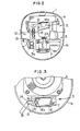
- the insert pipe 15 is initially mounted on the coiled spring 14 in the position as shown by phantom line, and is then turned in the anti-clockwise direction to be inserted into the inlet port 16a of the suction muffler 16, as shown by solid line.
- the coiled spring 14 exerts a torsional moment M on the insert pipe 15 to produce a biasing force P between the insert pipe 15 and the inlet port 16a.
- the suction muffler generally designated at numeral 16 is formed by injection molding from refrigerant resistant, oil resistant and heat resistant plastics such as polybutylene terephthalate, and is disposed away from the compressor section. As shown in Figure 4, the suction muffler 16 comprises a cup-shaped closure member 17, a cup-shaped body 18 and a partition plate 19. The cup-shaped body 18 is formed at its bottom with an aperture 21 through which extends a communication pipe 20 supportingly fitted into a suction port 7a of the cylinder head 7. The cup-shaped body 18 is also formed at its opening end with a sleeve portion 22 and a flat stepped portion 22a.
- the closure member 17 includes at its front and rear surfaces a pair of latches 17a adapted to engage with apertures 22b formed in the cup-shaped body 18.
- the partition plate 19 is formed with a pair of through holes 19a and is bent to be curved gradually from its center toward its right and left ends.
- the communication pipe 20 includes an integral flange 20a adapted to engage the peripheral edge of the aperture 21.
- the suction port 7a formed in the cylinder head 7 is communicated to a low pressure chamber (not shown) which in turn is communicated with a low pressure valve (not shown) provided in the cylinder head.
- a resilient member 23 such as a corrugated washer is mounted around the periphery of the communication pipe 20 between the cup-shaped body 18 and the cylinder head 7.
- the communication pipe 20 is inserted through the aperture 21 of the cup-shaped body 18 from inward thereof, and the resilient member 23 is set in place on the communication pipe 20, after which the pipe 20 is forcedly inserted into the suction port 7a of the cylinder head 7.
- the extent to which the communication pipe 20 is forced into the suction port 7a is such that the resilient member 23 is compressed to its minimum thickness against its elasticity at room temperatures, or alternatively is such that the resilient member 23 still remains slightly compressible allowing for expansion of the cup-shaped body 18 (more specifically, linear expansion of the body 18 plus linear expansion of the communication pipe 20) at high temperatures in operation.
- the partition plate 19 is placed in abutting relation to the stepped portion 22a of the cup-shaped body 18, after which the closure member 17 is urged against the elasticity of the partition plate 19 into the sleeve portion 22 of the body 18 to cause the latches 17 to engage the apertures 22b.
- the insert pipe 15, the suction pipe 13 fixed to the lower casing 1 b and the coiled spring 14 are previously assembled with the insert pipe 15 in the position as shown by phantom line in Figure 3.
- a unit consisting integrally of the motor section 2 and the compressor section 3 is contained and assembled in the following manner.
- the compressor section 3 is initially placed through a spring 3a in the lower casing 1b.
- the insert pipe 15 can be freely moved due to the elasticity of the coiled spring 14 as shown by phantom line in Figure 2, so that a torsional moment M is imparted to the coiled spring 14, that is, the spring 14 is twisted from the position as shown by phantom line in Figure 3 to the position as shown by solid line, to permit insertion of the insert pipe 15 into the inlet port 16a of the muffler 16, thus completing assembling.
- assembly of the motor compressor can be easily and rapidly effected, and the abutting force P is produced between the inlet port 16a of the muffler 16 and the insert pipe 15 owing to the torsional moment M to enable reducing humming sounds which would otherwise be produced between the inlet port 16a and the insert pipe 15.
- the direction of torsion for producing the torsional moment M is not decisive, and either of the directions of winding and unwinding the coiled spring 14 will suffice.
- the winding direction is preferable in increasing closeness between the coiled spring 14 and the insert pipe 15 or the suction pipe 13.
- the suction gas supply passage 12 is constituted by successively connecting the suction pipe 13, the closely coiled spring 14, the insert pipe 15 and the suction muffler 16, and is isolated from the heat generated by the compressor section 3. Accordingly, the suction gas is directly sucked in the suction muffler 16 without being exposed to the environment of high temperatures.
- the suction muffler 16 is connected through the insert pipe 15 and the coiled spring 14 to the suction pipe 13, so that it can follow relative movements of the elements of the compressor section provided in the sealed enclosure in the normal direction and in the upward and downward direction to reduce vibrations transmitted to the sealed enclosure from the elements of the compressor section.
- the inert pipe 15 is fitted in the suction muffler 16 with the minimum clearance therebetween required for sliding movements, so that it is moved in contact with the opening of the suction muffler 16 upon movements of the elements of the compressor section in the peripheral direction to mitigate load on the closely coiled spring 14.
- the minimum clearance between the insert pipe 15 and the opening of the suction muffler 16 which permits sliding movements therebetween prevents leakage of the refrigerant and mitigates resounding produced from the pulsation within the suction muffler.
- the torsional moment produced in the closely coiled spring gives rise to a force by which the insert pipe urges the inlet port of the suction muffler, so that any humming sounds which would otherwise be produced therebetween can be reduced, and rapid and simple assembly of the motor compressor can be performed.
Landscapes
- Engineering & Computer Science (AREA)
- Mechanical Engineering (AREA)
- General Engineering & Computer Science (AREA)
- Compressor (AREA)
Claims (9)
Applications Claiming Priority (8)
| Application Number | Priority Date | Filing Date | Title |
|---|---|---|---|
| JP13285081A JPS5835284A (ja) | 1981-08-25 | 1981-08-25 | 冷媒圧縮機の消音装置 |
| JP132850/81 | 1981-08-25 | ||
| JP159183/81U | 1981-10-26 | ||
| JP15918381U JPS5863382U (ja) | 1981-10-26 | 1981-10-26 | 密閉型電動圧縮機 |
| JP44270/82 | 1982-03-18 | ||
| JP4427182A JPS58160571A (ja) | 1982-03-18 | 1982-03-18 | 密閉型電動圧縮機 |
| JP4427082A JPS58160570A (ja) | 1982-03-18 | 1982-03-18 | 冷媒圧縮機の消音装置 |
| JP44271/82 | 1982-03-18 |
Publications (2)
| Publication Number | Publication Date |
|---|---|
| EP0073469A1 EP0073469A1 (de) | 1983-03-09 |
| EP0073469B1 true EP0073469B1 (de) | 1985-05-22 |
Family
ID=27461503
Family Applications (1)
| Application Number | Title | Priority Date | Filing Date |
|---|---|---|---|
| EP82107814A Expired EP0073469B1 (de) | 1981-08-25 | 1982-08-25 | Hermetisch geschlossener Kompressor |
Country Status (4)
| Country | Link |
|---|---|
| US (1) | US4531894A (de) |
| EP (1) | EP0073469B1 (de) |
| CA (1) | CA1210741A (de) |
| DE (1) | DE3263760D1 (de) |
Families Citing this family (22)
| Publication number | Priority date | Publication date | Assignee | Title |
|---|---|---|---|---|
| NL8403116A (nl) * | 1984-10-12 | 1986-05-01 | Philips Nv | Compressor. |
| IT1179810B (it) * | 1984-10-31 | 1987-09-16 | Aspera Spa | Gruppo motocompressore ermetico per circuiti frigoriferi |
| JPS62131966A (ja) * | 1985-12-04 | 1987-06-15 | Nippon Denso Co Ltd | 燃料ポンプの取付装置 |
| DE3622996A1 (de) * | 1986-07-09 | 1988-02-18 | Danfoss As | Saugschalldaempfer |
| DE68919845T2 (de) * | 1989-08-04 | 1995-07-13 | Matsushita Refrigeration | Hermetischer Verdichter. |
| IT218398Z2 (it) * | 1989-09-21 | 1992-05-05 | Zanussi Elettromecc | Compressori frigoriferi perfezionati. |
| JPH03258980A (ja) * | 1990-03-06 | 1991-11-19 | Matsushita Refrig Co Ltd | 密閉型電動圧縮機 |
| BR9102288A (pt) * | 1991-05-28 | 1993-01-05 | Brasileira S A Embraco Empresa | Conjunto abafador de succao para compressor hermetico |
| KR940003845Y1 (ko) * | 1991-12-28 | 1994-06-15 | 주식회사 금성사 | 밀폐형 전동압축기 |
| IT230572Y1 (it) * | 1992-12-21 | 1999-06-07 | Gold Star Co | Dispositivo di soppressione del rumore per un compressore ermetico a stantuffo |
| CN1078931C (zh) * | 1995-03-30 | 2002-02-06 | Lg电子株式会社 | 安装密闭式压缩机的消声器的装置 |
| CN1091844C (zh) * | 1995-04-28 | 2002-10-02 | Lg电子株式会社 | 用于装配密封式压缩机的吸气噪音消声器的装置 |
| KR0136621Y1 (ko) * | 1995-10-31 | 1999-03-20 | 구자홍 | 밀폐형 전동 압축기의 흡입소음기 체결구조 |
| KR100222924B1 (ko) * | 1996-07-12 | 2000-01-15 | 배길성 | 밀폐형 왕복동식 압축기 |
| JPH1082365A (ja) * | 1996-07-30 | 1998-03-31 | Samsung Electron Co Ltd | 吸入マフラーを有する密閉型圧縮器 |
| JP2000337254A (ja) * | 1999-05-27 | 2000-12-05 | Matsushita Refrig Co Ltd | 密閉型電動圧縮機 |
| CN101310956A (zh) * | 2003-10-10 | 2008-11-26 | 松下电器产业株式会社 | 吸入消声器的制造方法 |
| JP2005133707A (ja) * | 2003-10-10 | 2005-05-26 | Matsushita Electric Ind Co Ltd | 密閉型圧縮機 |
| TR200605252T1 (tr) * | 2004-03-26 | 2007-01-22 | Ar�El�K Anon�M ��Rket� | Bir kompresör |
| KR20080000996A (ko) * | 2006-06-28 | 2008-01-03 | 삼성광주전자 주식회사 | 밀폐형 압축기 |
| US9541310B2 (en) * | 2012-04-19 | 2017-01-10 | Mitsubishi Electric Corporation | Sealed compressor and vapor compression refrigeration cycle apparatus including the sealed compressor |
| US20180223825A1 (en) * | 2017-02-07 | 2018-08-09 | Lg Electronics Inc. | Reciprocating compressor and method of manufacturing a reciprocating compressor |
Family Cites Families (11)
| Publication number | Priority date | Publication date | Assignee | Title |
|---|---|---|---|---|
| US1015955A (en) * | 1911-06-07 | 1912-01-30 | Draper D Helder | Muffler. |
| US1927947A (en) * | 1931-02-03 | 1933-09-26 | Westinghouse Air Brake Co | Muffler |
| US2068187A (en) * | 1934-02-21 | 1937-01-19 | Lewis William Yorath | Heat transfer apparatus applicable to water tube boilers |
| US2213325A (en) * | 1939-01-31 | 1940-09-03 | Westinghouse Electric & Mfg Co | Refrigerating apparatus |
| DE1801721B1 (de) * | 1968-10-08 | 1970-10-01 | Danfoss As | Schalldaempfer fuer gekapselte Kaeltemittelverdichter |
| US3864064A (en) * | 1973-03-12 | 1975-02-04 | Sundstrand Corp | Suction muffler tube for compressor |
| US3876339A (en) * | 1973-08-06 | 1975-04-08 | Sundstrand Corp | Reciprocating piston gas compressor |
| US4086032A (en) * | 1976-08-23 | 1978-04-25 | Mitsubishi Jukogyo Kabushiki Kaisha | Sealed type motor-compressor |
| US4111278A (en) * | 1977-02-09 | 1978-09-05 | Copeland Corporation | Discharge muffler |
| US4240774A (en) * | 1979-02-15 | 1980-12-23 | General Electric Company | Hermetically sealed compressor suction tube and method of assembly |
| US4370104A (en) * | 1980-07-22 | 1983-01-25 | White Consolidated Industries, Inc. | Suction muffler for refrigeration compressor |
-
1982
- 1982-08-18 CA CA000409691A patent/CA1210741A/en not_active Expired
- 1982-08-25 DE DE8282107814T patent/DE3263760D1/de not_active Expired
- 1982-08-25 EP EP82107814A patent/EP0073469B1/de not_active Expired
-
1984
- 1984-04-27 US US06/604,403 patent/US4531894A/en not_active Expired - Lifetime
Also Published As
| Publication number | Publication date |
|---|---|
| US4531894A (en) | 1985-07-30 |
| EP0073469A1 (de) | 1983-03-09 |
| DE3263760D1 (en) | 1985-06-27 |
| CA1210741A (en) | 1986-09-02 |
Similar Documents
| Publication | Publication Date | Title |
|---|---|---|
| EP0073469B1 (de) | Hermetisch geschlossener Kompressor | |
| US4370104A (en) | Suction muffler for refrigeration compressor | |
| US5304044A (en) | Hermetic compressor | |
| US4573880A (en) | Hermetically sealed motor compressor | |
| US4911619A (en) | Suction system of hermetic refrigeration compressor | |
| US4904165A (en) | Muffler/check valve assembly for scroll compressor | |
| EP0582712B1 (de) | Hermetischer verdichter | |
| US4978285A (en) | Reed valve for hermetic compressor | |
| US4784581A (en) | Compressor head and suction muffler for hermetic compressor | |
| US7478996B2 (en) | Reciprocating compressor having assembly structure of suction muffler | |
| KR830010311A (ko) | 냉장고 압축기용 소음시스템 | |
| JPS6340944B2 (de) | ||
| JPH10339270A (ja) | 圧縮機の弁結合体 | |
| KR20100057680A (ko) | 모터-펌프 조립체 | |
| GB2093523A (en) | Compressor muffler | |
| US20230167825A1 (en) | A scroll compressor provided with a discharge muffler arrangement | |
| EP3587811B1 (de) | Linearverdichter | |
| US20040234386A1 (en) | Discharge muffler having an internal pressure relief valve | |
| KR20030074134A (ko) | 팽창밸브 및 그 케이스 | |
| CN100386519C (zh) | 用于密封式压缩机的阀组件 | |
| JPH11125178A (ja) | 斜板式圧縮機 | |
| CN115523148A (zh) | 一种压缩机的回油结构、压缩机和空调器 | |
| JPS6345480A (ja) | 流路切換弁付密閉容器 | |
| KR100217056B1 (ko) | 압축기 | |
| JPH0137596B2 (de) |
Legal Events
| Date | Code | Title | Description |
|---|---|---|---|
| PUAI | Public reference made under article 153(3) epc to a published international application that has entered the european phase |
Free format text: ORIGINAL CODE: 0009012 |
|
| AK | Designated contracting states |
Designated state(s): DE IT |
|
| 17P | Request for examination filed |
Effective date: 19830817 |
|
| ITF | It: translation for a ep patent filed | ||
| GRAA | (expected) grant |
Free format text: ORIGINAL CODE: 0009210 |
|
| AK | Designated contracting states |
Designated state(s): DE IT |
|
| REF | Corresponds to: |
Ref document number: 3263760 Country of ref document: DE Date of ref document: 19850627 |
|
| PLBE | No opposition filed within time limit |
Free format text: ORIGINAL CODE: 0009261 |
|
| STAA | Information on the status of an ep patent application or granted ep patent |
Free format text: STATUS: NO OPPOSITION FILED WITHIN TIME LIMIT |
|
| 26N | No opposition filed | ||
| ITTA | It: last paid annual fee | ||
| PGFP | Annual fee paid to national office [announced via postgrant information from national office to epo] |
Ref country code: DE Payment date: 20010718 Year of fee payment: 20 |