EP0073580A1 - Procédé pour enrouler une bande autour d'un tube - Google Patents
Procédé pour enrouler une bande autour d'un tube Download PDFInfo
- Publication number
- EP0073580A1 EP0073580A1 EP82304184A EP82304184A EP0073580A1 EP 0073580 A1 EP0073580 A1 EP 0073580A1 EP 82304184 A EP82304184 A EP 82304184A EP 82304184 A EP82304184 A EP 82304184A EP 0073580 A1 EP0073580 A1 EP 0073580A1
- Authority
- EP
- European Patent Office
- Prior art keywords
- pipe
- doctor blade
- sealing material
- tape
- doctor
- Prior art date
- Legal status (The legal status is an assumption and is not a legal conclusion. Google has not performed a legal analysis and makes no representation as to the accuracy of the status listed.)
- Granted
Links
- 238000000034 method Methods 0.000 title claims abstract description 38
- 239000003566 sealing material Substances 0.000 claims abstract description 37
- 239000011324 bead Substances 0.000 claims abstract description 26
- 239000004831 Hot glue Substances 0.000 claims abstract description 16
- 239000007788 liquid Substances 0.000 claims abstract description 7
- 230000007704 transition Effects 0.000 claims abstract description 4
- 239000011248 coating agent Substances 0.000 claims description 10
- 238000000576 coating method Methods 0.000 claims description 10
- 239000000853 adhesive Substances 0.000 claims description 5
- 230000001070 adhesive effect Effects 0.000 claims description 5
- 238000010438 heat treatment Methods 0.000 claims description 5
- 238000001125 extrusion Methods 0.000 claims description 4
- 239000002184 metal Substances 0.000 claims description 4
- 229910001220 stainless steel Inorganic materials 0.000 claims description 4
- 239000010935 stainless steel Substances 0.000 claims description 4
- 239000000565 sealant Substances 0.000 description 9
- 230000000712 assembly Effects 0.000 description 2
- 238000000429 assembly Methods 0.000 description 2
- 241000276420 Lophius piscatorius Species 0.000 description 1
- 238000009825 accumulation Methods 0.000 description 1
- 238000001816 cooling Methods 0.000 description 1
- 230000007613 environmental effect Effects 0.000 description 1
- 239000000463 material Substances 0.000 description 1
- 239000007921 spray Substances 0.000 description 1
Images

Classifications
-
- B—PERFORMING OPERATIONS; TRANSPORTING
- B05—SPRAYING OR ATOMISING IN GENERAL; APPLYING FLUENT MATERIALS TO SURFACES, IN GENERAL
- B05D—PROCESSES FOR APPLYING FLUENT MATERIALS TO SURFACES, IN GENERAL
- B05D1/00—Processes for applying liquids or other fluent materials
- B05D1/40—Distributing applied liquids or other fluent materials by members moving relatively to surface
- B05D1/42—Distributing applied liquids or other fluent materials by members moving relatively to surface by non-rotary members
Definitions
- This invention relates to a method and apparatus for wrapping a tape around a pipe.
- a sealing material eg. a hot melt adhesive
- the relative movement of the tape and the pipe required during the wrapping can be provided by spiralling a tape supply around a fixed pipe, by rotating a tape supply around a pipe which is advanced axially only, or by pulling tape from a fixed tape supply onto a pipe which is simultaneously advanced axially and rotated.
- Certain types of metal pipe especially those having relative large diameters, eg. greater than 18 inch, have a longitudinal weld bead protruding from the surface thereof (eg. double submerged arc weld, DSAW, pipes).
- DSAW double submerged arc weld
- Such pipes present problems when tape wrapped, because the tape tends to form a tent over the weld bead, leaving two longitudinal voids, one each side of the weld bead. These voids are undesirable, especially because they provide sites for accumulation of moisture.
- Various methods have been proposed for overcoming this difficulty, but all suffer from serious disadvantages. For example, attempts have been made to use rollers to press the tape wrapping into the grooves on either side of the weld bead, but most tape wraps are too resilient for this to be successful.
- the grooves are filled with a sealing material, before the tape wrap is applied, by forwarding the pipe axially only (i.e. not simultaneously rotating .it), applying a viscous liquid sealing material to the area around the weld bead and doctoring the sealing material by means of a doctor blade placed generally at right angles to the axis of the pipe; the tape is then applied by spiralling a tape supply around the pipe as it is forwarded axially only.
- This method requires that the weld bead be accurately positioned before the process begins. Furthermore it is much more difficult to obtain - good tape wrapping by spiralling the tape supply around the pipe than when the pipe is rotated, especially when the pipe and the tape are heated.
- the tape wrapping can be performed in a separate operation in which the pipe is simultaneously rotated and forwarded, but this is inconvenient, and furthermore the tires (or other means) used to rotate the pipe deform the sealant which has been doctored into the grooves, especially if the pipe and sealant are heated.
- the invention also includes apparatus suitable - for carrying out the method defined above, the apparatus comprising:
- the apparatus preferably additionally comprises heating means for heating the pipe as it is advanced and rotated by the forwarding means, this allows a hot-melt adhesive to be used as the viscous liquid sealing material, since it can attain the required physical state on contact with the pipe.
- doctor blades are circumferentially spaced apart and longitudinally positioned so that when a pipe bearing a sealing material, such as an adhesive, is forwarded through the doctoring means, the section of the pipe which passes under the trailing end of one doctor blade subsequently passes under a central section of another doctor blade.
- a sealing material such as an adhesive
- a single doctor blade is sufficient to carry out the process of the invention, provided it is sufficiently long to sweep the entire surface of the pipe; the or each doctor blade preferably has a length of at least 1.5 x d, especially at least 2 x d, where d is the axial distance which the pipe advances as it is rotated once.
- a central section is meant a section which is at least 0.1 x 1, preferably at least 0.25 x 1, where 1 is the length of the doctor blade, from each end of the doctor blade).
- central section is meant a section which is at least 0.1 x 1, preferably at least 0.25 x 1, where 1 is the length of the doctor blade, from each end of the doctor blade.
- the doctor blade must be resiliently flexible so that it will conform generally to the surface of the pipe and accommodate passage of the weld bead underneath it. It must also be strong enough to doctor the viscous sealing material, and thus retain a bank of the sealing material between it and the advancing pipe.
- stainless steel to be a suitable material for the doctor blade. For doctoring a hot melt adhesive applied to a pipe of diameter about 36 inches (91.4 cm), I believe that it will be satisfactory to use a doctor blade about 24 inches (61 cm) long and 4 inches (10.2 cm) high and cut from stainless steel sheet of 14 to 26 gauge, e.g. about 16 gauge.
- the operation of the doctor blade is affected by the angle, ⁇ , between the surface of the doctor blade and the advancing pipe surface as it passes under the doctor blade, which is preferably 20° to 80°, especially 30° to 60'.
- the smaller the angler the more likely it is that the sealant will deform the blade and creep under it; the larger the angle ⁇ , the more rigid the blade in operation and therefore the less likely that the desired conformance between blade and pipe will be achieved.
- the angle, ⁇ , between the axis of the doctor blade and the axis of the pipe, also affects the operation of the doctor blade, and is preferably from 10 to 40', particularly 15° to 30°, especially about 20'. If ⁇ is too small, sealing material tends to spill off the leading end of the blade, and if ⁇ is too large the blade cannot conform sufficiently to the pipe surface.
- any viscous liquid sealing material can be used in the invention, but the invention is particularly useful when.
- a hot sealant eg. at a temperature of at least 100°C, eg. a hot melt adhesive
- Suitable sealants include for example hot-melt adhesives of melt index at 150°C in the range of 30 to 130, eg. 50-55, applied at temperatures in the range of 150° to 240°C eg. 175° to 220.
- hot sealants the pipe is usually also heated, eg. to a temperature of at least 100°C.
- the sealant is doctored into smooth coating all over the pipe, the coating being of uniform thickness except in the area of the weld bead, where the thickness of the sealant is greater in the grooves either side of the weld bead, and less over the top of the weld bead.
- the pipes used in this invention may be of any size, but pipes having longitudinal weld beads are usually at least 15 inches, e.g. 24 to 48 inches, in diameter.
- the tape used in the invention is usually a polymeric tape, often one having a coating of a sealing material on its interior surface.
- the sealing material is preferably the same as that applied to the pipe and doctored by the doctor blades.
- the tape and adhesive coating are preferably heated before being applied to the pipe.
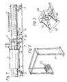
- Figure 1 shows a pipe 1 having weld bead 11, the pipe being simultaneously advanced axially and rotated by drive wheels 9.
- the pipe is forwarded sequentially through an oven 2, in which the pipe is heated; through heat shield 3; past extrusion nozzle 4 through which molten hot-melt adhesive is extruded onto the pipe; through doctoring station 5 (shown in more detail in Figures 2 and 3) in which the adhesive is doctored to a uniform exterior finish; through tape-wrapping station 6 in which tape 61 having a coating of hot melt adhesive is drawn from tape supply 62 and is applied in spiral overlapping fashion to the pipe 1 with the aid of roller 63; and finally under cooling spray 7.
- Figures 2 and 3 show the doctoring station 5 in more detail.
- Frame 51 carried a pair of identical doctor blade assemblies (as shown in greater detail in Figure 3) which press doctor blades against diametrically opposed parts of the pipe. Only one of the blade assemblies is shown in Figure 2.
- Doctor blade 52 is resiliently urged against the pipe surface by means of spring-loaded pistons 53 which form part of three-dimensionally adjustable sub-frame 54.
- Figures 4 and 5 clarify the angular relationships between the doctor blades 52 and the pipe 1, in particular the anglesC ⁇ and ⁇ . Also shown in Figure 4 is a coating 41 of hot melt adhesive, varying in thickness in the region of the weld bead 11.
Landscapes
- Coating Apparatus (AREA)
- Application Of Or Painting With Fluid Materials (AREA)
- Lining Or Joining Of Plastics Or The Like (AREA)
- Protection Of Pipes Against Damage, Friction, And Corrosion (AREA)
- Adhesives Or Adhesive Processes (AREA)
- Shaping Of Tube Ends By Bending Or Straightening (AREA)
Priority Applications (1)
| Application Number | Priority Date | Filing Date | Title |
|---|---|---|---|
| AT82304184T ATE16366T1 (de) | 1981-08-10 | 1982-08-09 | Verfahren zum umwickeln eines rohres mit einem band. |
Applications Claiming Priority (2)
| Application Number | Priority Date | Filing Date | Title |
|---|---|---|---|
| US06/291,689 US4372796A (en) | 1981-08-10 | 1981-08-10 | Method and apparatus for wrapping a tape around a pipe |
| US291689 | 1981-08-10 |
Publications (2)
| Publication Number | Publication Date |
|---|---|
| EP0073580A1 true EP0073580A1 (fr) | 1983-03-09 |
| EP0073580B1 EP0073580B1 (fr) | 1985-11-06 |
Family
ID=23121398
Family Applications (1)
| Application Number | Title | Priority Date | Filing Date |
|---|---|---|---|
| EP82304184A Expired EP0073580B1 (fr) | 1981-08-10 | 1982-08-09 | Procédé pour enrouler une bande autour d'un tube |
Country Status (6)
| Country | Link |
|---|---|
| US (1) | US4372796A (fr) |
| EP (1) | EP0073580B1 (fr) |
| AT (1) | ATE16366T1 (fr) |
| CA (1) | CA1174958A (fr) |
| DE (1) | DE3267293D1 (fr) |
| GB (1) | GB2104616B (fr) |
Cited By (2)
| Publication number | Priority date | Publication date | Assignee | Title |
|---|---|---|---|---|
| EP0121017A3 (en) * | 1983-03-31 | 1985-09-11 | William David Brewer | Method of manufacturing laminated plastics material |
| DE3619973C1 (en) * | 1986-06-13 | 1987-11-12 | Vahlbrauk Karl Heinz | Process for producing a jacketed pipe |
Families Citing this family (17)
| Publication number | Priority date | Publication date | Assignee | Title |
|---|---|---|---|---|
| GB8308704D0 (en) * | 1983-03-29 | 1983-05-05 | British Nuclear Fuels Ltd | Removing excess material from composite body |
| ATE30130T1 (de) * | 1983-03-31 | 1987-10-15 | William David Brewer | Verfahren zur herstellung von mehrschichtigen kunststoffmaterialien. |
| US4574023A (en) * | 1984-01-26 | 1986-03-04 | Raychem Corporation | Apparatus and method for applying sleeves to pipe |
| AT393552B (de) * | 1984-10-17 | 1991-11-11 | Trest Juzhvodoprovod | Rohrleitung sowie verfahren und einrichtung zur rohrleitungsverlegung |
| IT1185728B (it) * | 1985-11-20 | 1987-11-12 | Colbachini Spa | Impianto per la confezione di tubi in gomma,provvisto di caratteristiche costruttive atte a permettere un perfetto allineamento delle anime,di qualsiasi diametro,rispetto alle teste motrici di rotazione |
| USRE35526E (en) * | 1989-03-07 | 1997-06-10 | Newell Operating Company | Method and apparatus for manufacturing paint roller and product produced thereby |
| US5273604A (en) * | 1990-03-06 | 1993-12-28 | Ez Paintr Corporation | Method and apparatus for manufacturing paint roller and product produced thereby |
| EP0630316B1 (fr) * | 1992-03-09 | 1998-01-07 | N.V. Raychem S.A. | Procede d'application d'un materiau de couverture sur un substrat allonge |
| US5273611A (en) * | 1992-05-04 | 1993-12-28 | Sig-A-Rap | Apparatus for applying a continuous film to a pipeline |
| IT1264781B1 (it) * | 1993-04-06 | 1996-10-10 | Himont Inc | Procedimento per il rivestimento di tubi metallici con materiali poliolefinici |
| GB9322092D0 (en) * | 1993-10-27 | 1993-12-15 | Raychem Sa Nv | Article and method for protecting substrates |
| WO1995013915A1 (fr) * | 1993-11-15 | 1995-05-26 | Liquid Carbonic Corporation | Dispositif d'isolation souple et n'absorbant pas l'eau |
| US5871818A (en) * | 1995-11-01 | 1999-02-16 | Illinois Superconductor Corporation | Thick film coating process |
| US6539999B2 (en) | 2001-02-19 | 2003-04-01 | Newell Operating Company | Apparatus and method for making variable paint roller covers |
| RU2190531C1 (ru) * | 2001-06-22 | 2002-10-10 | Закрытое акционерное общество "НПП Композит-нефть" | Способ изготовления трубы |
| CA2537348A1 (fr) * | 2006-02-22 | 2007-08-22 | Shawcor Ltd. | Methode de revetement de tuyaux ayant un cordon de soudure |
| US20110041994A1 (en) * | 2009-08-20 | 2011-02-24 | Randall Heath | Method and Apparatus for Encasing a Wooden Member |
Citations (4)
| Publication number | Priority date | Publication date | Assignee | Title |
|---|---|---|---|---|
| US2863204A (en) * | 1955-03-08 | 1958-12-09 | Sauthern Natural Gas Company | Pipe coating method and apparatus |
| DE2243741A1 (de) * | 1971-09-09 | 1973-03-22 | Oesterr Alpine Montan | Verfahren zur kontinuierlichen erzeugung einer schicht aus thermoplastischen kunststoffen auf stahlrohren |
| DE2407427B2 (de) * | 1974-02-12 | 1977-01-20 | Mannesmann AG, 4000 Düsseldorf | Verfahren und vorrichtung zum ummanteln eines eine laengsnaht aufweisenden stahlrohres mit einem folienband aus einem thermoplastischen kunststoff |
| DE2900597B1 (de) * | 1979-01-05 | 1980-06-04 | Mannesmann Ag, 4000 Duesseldorf | Vorrichtung zum Beschichten von Stahlrohren mit thermoplastischem Kunststoff |
Family Cites Families (4)
| Publication number | Priority date | Publication date | Assignee | Title |
|---|---|---|---|---|
| US1796691A (en) * | 1930-05-28 | 1931-03-17 | Gen Paint Corp | Pipe-coating machine |
| US2044778A (en) * | 1934-04-21 | 1936-06-23 | Johns Manville | Pipe coating machine |
| US3525656A (en) * | 1967-05-09 | 1970-08-25 | Trenton Corp The | Method of simultaneously applying a flexible plastic film and a flexible carrier board to a pipe |
| US3761335A (en) * | 1970-02-26 | 1973-09-25 | Steel Corp | Method for the wiping transfer of bonding agent onto a longitudinal member and an underlapping margin of a tape on the longitudinal member |
-
1981
- 1981-08-10 US US06/291,689 patent/US4372796A/en not_active Expired - Lifetime
-
1982
- 1982-08-09 AT AT82304184T patent/ATE16366T1/de not_active IP Right Cessation
- 1982-08-09 EP EP82304184A patent/EP0073580B1/fr not_active Expired
- 1982-08-09 GB GB08222904A patent/GB2104616B/en not_active Expired
- 1982-08-09 DE DE8282304184T patent/DE3267293D1/de not_active Expired
- 1982-08-10 CA CA000409100A patent/CA1174958A/fr not_active Expired
Patent Citations (4)
| Publication number | Priority date | Publication date | Assignee | Title |
|---|---|---|---|---|
| US2863204A (en) * | 1955-03-08 | 1958-12-09 | Sauthern Natural Gas Company | Pipe coating method and apparatus |
| DE2243741A1 (de) * | 1971-09-09 | 1973-03-22 | Oesterr Alpine Montan | Verfahren zur kontinuierlichen erzeugung einer schicht aus thermoplastischen kunststoffen auf stahlrohren |
| DE2407427B2 (de) * | 1974-02-12 | 1977-01-20 | Mannesmann AG, 4000 Düsseldorf | Verfahren und vorrichtung zum ummanteln eines eine laengsnaht aufweisenden stahlrohres mit einem folienband aus einem thermoplastischen kunststoff |
| DE2900597B1 (de) * | 1979-01-05 | 1980-06-04 | Mannesmann Ag, 4000 Duesseldorf | Vorrichtung zum Beschichten von Stahlrohren mit thermoplastischem Kunststoff |
Non-Patent Citations (2)
| Title |
|---|
| PATENT ABSTRACTS OF JAPAN, vol. 4, no. 49, 15 April 1980, page 135M7 & JP - A - 55 - 19511 * |
| PATENT ABSTRACTS OF JAPAN, vol. 5, no. 143, 9 September 1981, page 94M87 & JP - A - 56 - 75827 * |
Cited By (2)
| Publication number | Priority date | Publication date | Assignee | Title |
|---|---|---|---|---|
| EP0121017A3 (en) * | 1983-03-31 | 1985-09-11 | William David Brewer | Method of manufacturing laminated plastics material |
| DE3619973C1 (en) * | 1986-06-13 | 1987-11-12 | Vahlbrauk Karl Heinz | Process for producing a jacketed pipe |
Also Published As
| Publication number | Publication date |
|---|---|
| EP0073580B1 (fr) | 1985-11-06 |
| US4372796A (en) | 1983-02-08 |
| GB2104616A (en) | 1983-03-09 |
| GB2104616B (en) | 1985-10-09 |
| CA1174958A (fr) | 1984-09-25 |
| DE3267293D1 (en) | 1985-12-12 |
| ATE16366T1 (de) | 1985-11-15 |
Similar Documents
| Publication | Publication Date | Title |
|---|---|---|
| US4372796A (en) | Method and apparatus for wrapping a tape around a pipe | |
| EP1016514B1 (fr) | Procédé et appareil pour la protection anticorrosion in-situ d'un joint de soudure de tuyaux métalliques | |
| US4929409A (en) | Method in manufacturing a heat insulated tube and a device in extruders for manufacturing the tube | |
| US4946528A (en) | Method and equipment for producing protective-coated steel pipe | |
| CA1108042A (fr) | Rouleau presseur et methode de guipage de tuyaux en acier avec une bande thermoplastique | |
| US3813272A (en) | Method and apparatus for simultaneously applying to an extended cylinmethod and apparatus for simultaneously applying to an extended cylindrical object a coating and a plastic film wrapping to retain the coating | |
| US4780158A (en) | Novel method for heating cylindrical articles and apparatus useful therefor | |
| EP0845691B1 (fr) | Câble optique avec une ame tubulaire métallique | |
| US4287223A (en) | Covering a steel pipe having a welding seam with a thermoplastic coating | |
| KR20010000056A (ko) | 복합관의 롤포밍장치 | |
| RU2141385C1 (ru) | Способ изготовления изоляционной ленты и установка для его осуществления | |
| MXPA04002954A (es) | Proceso y aparato para aplicar en continuo un recubrimiento externo a un tubo. | |
| DE3342023A1 (de) | Verfahren zur hersellung eines kunststoffrohres mit permeationssperre | |
| CN110191791B (zh) | 涂覆管件的内表面的方法及具有涂层的管件 | |
| JPH01130934A (ja) | 溶接ビードのある防食被覆鋼管の製造装置 | |
| GB1588399A (en) | Laminated plastics/metal tube | |
| EP2074346B1 (fr) | Procede et appareil de revetement pour une section de tuyau en laine minerale pour l'isolation thermique de tuyaux | |
| Nadeau | Manufacture of Plastic Jacketed Steel Pipe | |
| DE3445659C2 (de) | Kalibrierrohr für durchlaufendes Gut | |
| JPH02295723A (ja) | コルゲート管の製造方法およびその製造装置 | |
| DE4320361A1 (de) | Verfahren zur Herstellung eines korrosionsgeschützten gewellten Metallrohres | |
| JPS61167534A (ja) | 熱収縮性チユ−ブの連続的製造法 | |
| Tarnogrodskii et al. | Flattening and Welding Up of Thermoplastic Pipe Edges | |
| JPH01131732A (ja) | 防食被覆鋼管及びその製造方法 | |
| JPH01295825A (ja) | 防食被覆鋼管の製造方法と製造装置 |
Legal Events
| Date | Code | Title | Description |
|---|---|---|---|
| PUAI | Public reference made under article 153(3) epc to a published international application that has entered the european phase |
Free format text: ORIGINAL CODE: 0009012 |
|
| 17P | Request for examination filed |
Effective date: 19820902 |
|
| AK | Designated contracting states |
Designated state(s): AT BE CH DE FR IT LI NL SE |
|
| ITF | It: translation for a ep patent filed | ||
| GRAA | (expected) grant |
Free format text: ORIGINAL CODE: 0009210 |
|
| AK | Designated contracting states |
Designated state(s): AT BE CH DE FR IT LI NL SE |
|
| REF | Corresponds to: |
Ref document number: 16366 Country of ref document: AT Date of ref document: 19851115 Kind code of ref document: T |
|
| REF | Corresponds to: |
Ref document number: 3267293 Country of ref document: DE Date of ref document: 19851212 |
|
| ET | Fr: translation filed | ||
| PLBE | No opposition filed within time limit |
Free format text: ORIGINAL CODE: 0009261 |
|
| STAA | Information on the status of an ep patent application or granted ep patent |
Free format text: STATUS: NO OPPOSITION FILED WITHIN TIME LIMIT |
|
| 26N | No opposition filed | ||
| ITTA | It: last paid annual fee | ||
| EAL | Se: european patent in force in sweden |
Ref document number: 82304184.3 |
|
| PGFP | Annual fee paid to national office [announced via postgrant information from national office to epo] |
Ref country code: FR Payment date: 19950809 Year of fee payment: 14 Ref country code: DE Payment date: 19950809 Year of fee payment: 14 |
|
| PGFP | Annual fee paid to national office [announced via postgrant information from national office to epo] |
Ref country code: AT Payment date: 19950811 Year of fee payment: 14 |
|
| PGFP | Annual fee paid to national office [announced via postgrant information from national office to epo] |
Ref country code: CH Payment date: 19950814 Year of fee payment: 14 |
|
| PGFP | Annual fee paid to national office [announced via postgrant information from national office to epo] |
Ref country code: SE Payment date: 19950816 Year of fee payment: 14 |
|
| PGFP | Annual fee paid to national office [announced via postgrant information from national office to epo] |
Ref country code: NL Payment date: 19950825 Year of fee payment: 14 |
|
| PGFP | Annual fee paid to national office [announced via postgrant information from national office to epo] |
Ref country code: BE Payment date: 19950926 Year of fee payment: 14 |
|
| PG25 | Lapsed in a contracting state [announced via postgrant information from national office to epo] |
Ref country code: AT Effective date: 19960809 |
|
| PG25 | Lapsed in a contracting state [announced via postgrant information from national office to epo] |
Ref country code: SE Effective date: 19960810 |
|
| PG25 | Lapsed in a contracting state [announced via postgrant information from national office to epo] |
Ref country code: LI Effective date: 19960831 Ref country code: CH Effective date: 19960831 Ref country code: BE Effective date: 19960831 |
|
| BERE | Be: lapsed |
Owner name: RAYCHEM CORP. Effective date: 19960831 |
|
| PG25 | Lapsed in a contracting state [announced via postgrant information from national office to epo] |
Ref country code: NL Effective date: 19970301 |
|
| REG | Reference to a national code |
Ref country code: CH Ref legal event code: PL |
|
| PG25 | Lapsed in a contracting state [announced via postgrant information from national office to epo] |
Ref country code: FR Effective date: 19970430 |
|
| NLV4 | Nl: lapsed or anulled due to non-payment of the annual fee |
Effective date: 19970301 |
|
| PG25 | Lapsed in a contracting state [announced via postgrant information from national office to epo] |
Ref country code: DE Effective date: 19970501 |
|
| EUG | Se: european patent has lapsed |
Ref document number: 82304184.3 |
|
| REG | Reference to a national code |
Ref country code: FR Ref legal event code: ST |